EP0060142A1 - Détecteur d'approche à pression d'air et appareil de comptage comportant un tel détecteur - Google Patents
Détecteur d'approche à pression d'air et appareil de comptage comportant un tel détecteur Download PDFInfo
- Publication number
- EP0060142A1 EP0060142A1 EP82301208A EP82301208A EP0060142A1 EP 0060142 A1 EP0060142 A1 EP 0060142A1 EP 82301208 A EP82301208 A EP 82301208A EP 82301208 A EP82301208 A EP 82301208A EP 0060142 A1 EP0060142 A1 EP 0060142A1
- Authority
- EP
- European Patent Office
- Prior art keywords
- passage
- air
- probe
- air pressure
- pressure sensor
- Prior art date
- Legal status (The legal status is an assumption and is not a legal conclusion. Google has not performed a legal analysis and makes no representation as to the accuracy of the status listed.)
- Ceased
Links
Images


Classifications
-
- G—PHYSICS
- G06—COMPUTING OR CALCULATING; COUNTING
- G06M—COUNTING MECHANISMS; COUNTING OF OBJECTS NOT OTHERWISE PROVIDED FOR
- G06M7/00—Counting of objects carried by a conveyor
- G06M7/08—Counting of objects carried by a conveyor wherein the direction of movement of the objects is changed at the station where they are sensed
- G06M7/10—Counting of flat overlapped articles, e.g. of cards
-
- G—PHYSICS
- G06—COMPUTING OR CALCULATING; COUNTING
- G06M—COUNTING MECHANISMS; COUNTING OF OBJECTS NOT OTHERWISE PROVIDED FOR
- G06M1/00—Design features of general application
- G06M1/08—Design features of general application for actuating the drive
- G06M1/12—Design features of general application for actuating the drive by fluid means
- G06M1/123—Design features of general application for actuating the drive by fluid means by pneumatic means
-
- G—PHYSICS
- G06—COMPUTING OR CALCULATING; COUNTING
- G06M—COUNTING MECHANISMS; COUNTING OF OBJECTS NOT OTHERWISE PROVIDED FOR
- G06M2207/00—Indexing scheme relating to counting of objects carried by a conveyor
- G06M2207/02—Counting of generally flat and overlapped articles, e.g. cards, newspapers
Definitions
- This invention relates to air pressure sensors and is particularly although not exclusively, applicable to air pressure sensors for use in batch counting apparatus such as apparatus for counting signatures delivered in a "shingled" stream from a printing machine to a batching machine to form the required batches of signatures for subsequent binding.
- the invention provides air pressure sensor comprising a first air passage, a branch passage having an opening into the air passage, means in the branch passage responsive to variation in air pressure in the opening and jet means for air flow through the first passage adjacent the opening to the branch passage to create an increased depression inside static pressure as compared with the remainder of the air passage to enhance the response of the pressure responsive means in the branch passage when air flow through the first passage occurs.
- the air passage may terminate in a probe having an orifice to be opened and closed by the absence of and presence of a surface in contact with the probe so that the pressure responsive means indicates whether or not the probe is in contact with a surface,
- the probe may be mounted on a swinging arm to bear against articles in a "shingled" stream of articles moving past the probe so that as the probe breaks contact with each article in turn and the increased air flow permitted through the orifice of the probe causes the pressure responsive means to be actuated.
- the probe may be mounted on a parallel linkage to bear on a shingled stream of articles moving past the probe so that the probe can rise and fall as the stream of articles passes below it.
- the pressure responsive means may comprise an element located in the branch passage and displaceable along the branch passage in accordance with variation in pressure in the first passage and electric switch means may be provided to detect and respond to movement of the element towards the first passage when pressure therein falls.
- the pressure responsive means may comprise a solid state pressure transducer operated electric switch device.
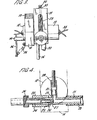
- the counting device 5 comprises a probe and pressure sensor assembly comprising an elongate base member 10 having on one side thereof an upstanding pressure sensor block 11.
- the sensor block 11 has laterally projecting part cylindrical housings 12 on either side thereof and the other housing is received in a part cylindrical recess formed in the upper surface,of the base plate 10 and is secured thereto by a clamping block 10a having a corresponding recess in its undersurface.
- the clamping block 12 is secured to the base 10 by bolts 13,
- an axle rotatably mounted in a bore through the base to rotate about a horizontal axis in a bearing 14a.
- One end of the axle 14 has a boss 15 thereon to which an arm 16 is secured at one end.
- the other end of the arm carries a tubular probe 17 having a contact face 18 at one end thereof.
- the tubular passage through the probe terminates in a round hole 19 in the contact face.
- the other end of the probe receives one end of the flexible air tube 20 the other end of which is connected to a tubular metal conduit 21 extending into the lower end of the sensor block 11. Downward tilting of the arm is limited by a stop 9 on the block 10 again which arm 16 engages.
- the tube 21 extends into the block into a sleeve 22 extending into the block from the other side thereof, the end of the sleeve 22 being welded to the tube 21 as indicated at 23.
- a jet 24 is screwed into the sleeve 22, the jet having an encircling knurled ring 25 and being formed with a reduced diameter portion 26 terminating in a jet orifice 27.
- the jet is connected to a source of air pressure which may be of the order of 12 to 40 lbs per square inch as required to provide an air flow through the jet and conduit 21.
- the conduit 21 has a side branch formed by a short conduit 28 extending upwardly from the conduit 21 adjacent the outlet of the jet orifice.
- a glass tube 29 is fitted over the branch conduit 28 and extends upwardly therefrom through the block 11.
- a P.T.F.E. plunger 31 is located in the glass tube, the plunger having a diameter slightly less than the internal diameter of the tube so that the plunger can rise and fall in the tube. Downward movement of the plunger in the tube is limited by engagement of the plunger with the upper edge of the branch conduit 28. Upward movement of the plunger in the tube is limited by a bolt 32 screwed into the top of the sensor block and extending into the upper end of the glass tube 29. The bolt is locked in position by a lock nut 33 and the top of the sensor block.
- One of the housings 12 contains a light source (not shown) for a photo-electric cell energised through wiring 34, the light source being directed across the sensor block 11 through the glass 29 adjacent the lower end of the stop screw 32.
- a photo-electric cell (not shown) is mounted in the housing 12 on the other side of the sensor block and is connected in a circuit arrangement to trigger a counting device (not shown). The light path between the light source and photo-electric cell is obstructed by the plunger 31 when the plunger is in engagement with the lower end of the bolt 32.
- the probe 17 of the counting device trails the axle about which it swings in the direction of travel of the conveyor 7 and is biassed downwardly into engagement with the top of the stream of book signatures 6 moving "fold -first" along the conveyor by a spring 35 extending between a lever arm 36 fastened in one end of the axle 14 and an anchorage 37 on the base member 10.
- the probe 17 is intended to bear on the surface of a signature below it and the sensor is intended to detect whenever contact between the probe and the surface is broken as the probe passes from one signature to the next.
- Contact of the end 18 of the probe with the surface restricts the escape of air from the outlet hole 19 so that the system is held under pressure from the air supply connected to the jet 24.
- the air pressure in the system forces the plunger 31 to the upper limit of its travel against the bolt 32.
- the optical path between the light source and photo-electric cell is thus obstructed and the circuit for triggering the counting device is inoperative.
- the air pressure in the probe and the force of the spring are so selected that the probe end is supported on a cushion of air slightly above the surface of a signature so that there is some small continuous loss of air from the probe but wear of the contact end of the probe by rubbing on the signature surfaces is avoided. Also smearing of freshly applied.ink to the signatures is avoided.
- air is allowed to escape freely from the hole 19 and the air flow through the jet orifice 27 in the pressure sensor establishes a low pressure zone adjacent the branch conduit 28 which draws the plunger 31 rapidly down the tube 29 until it engages the stop provided by the end of the conduit 28. It has been found that with the embodiment illustrated an air pressure supply of 20 p.s.i.
- the plunger 31 could be replaced by a steel ball arranged to ride up and down the tube 29 in accordance with variations of air pressure therein.
- the plunger/light source/photo-electric cell arrangement is replaced by a solid state pressure transducer operated electric switch and associated electronic circuitry for counting the signatures.
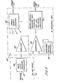
- FIG. 5 and 6 of the drawings illustrates, respectively, the electronic circuitry for the solid state transducer operated version of the probe and a modification of the arrangement shown in Figure 4 to accept the solid state transducer.
- the photoelectric cell and associated light source and the plunger 31 are omitted.
- a solid state pressure transducer 40 is mounted on the branch conduit 28 with the pressure input side 41 of the transducer in communication with the conduit 21 immediately downstream of the jet orifice 27.
- the transducer 40 is connected to a circuit system indicated generally at 42 having a power supply circuit 43 and including an amplifier 44, a comparator 45 also connected to an adjustable voltage 46 and an output circuit 47 which includes high and low pressure indicators to indicate the mode of operation of the probe and a connection 48 to a counter to count each time the transducer triggers the circuit.
- the pressure transducer may, for example, be a transducer sold under the name "Monolithic Pressure Transducer" by National Semiconductor Corporation.
- the apparatus operates in a similar manner to that of the first embodiment described.
- the probe arm climbs the leading edge, and the nozzle partially seals against the signature surface.
- This pressure change is sensed by a solid-state pressure transducer integrated-circuit device, which in conjunction with an operational amplifier circuit, produces a logic signal representing a single count.
- the air pressure momentarily falls as the nozzle climbs each edge, then rises again as the nozzle seals against the signature surface.
- a count pulse is obtained for every signature.
- the solid state pressure transducer is mounted within the mechanical assembly of the probe, with a four-core screened cable (2m long) provided for connection into the separate interface box.
- the electronics unit within the interface box provides the means for two important paramaters to be controlled.
- a three position switch In order that a user can easily select the correct conditions for optimum count performance on signatures within a pre-determined thickness range, a three position switch is provided. In each switch position, separate preset controls are brought into operation for pressure threshold. Red and green indicator LED's are provided so that the operation of the device can be monitored visually. The green LED “LO” lights when the probe nozzle is clear of the signature surface. The red LED “HI” lights when the nozzle is sealed by the signature surface (i.e. one count pulse generated).
- the interface box has a clear plastic front, through which may be viewed
- the three position switch available to the user has a shaft protruding through the clear plastic lid, and is fitted with a collet knob.
- the pressure- transducer is a strain-sensitive semi-conductor bridge. Pressure applied to the transducer port induces a strain which changes the out-of-balance voltage across the bridge.
- the bridge is provided with a stable D.C. supply of say, 6.9 volts, from a reference voltage source.
- the bridge output voltage is applied across the differential inputs of an operational amplifier, operated at a fixed gain of 15.
- the amplifier output is applied to a second stage operational amplifier, which functions as a Schmidt trigger with a fixed degree of hysteresis (to obtain clean switching, with no jitter around the threshold point).
- the fixed amount of hysteresis applied is however considerable; this also ensures that once a signature edge has been detected, the system becomes insensitive to minor pressure drops due to imperfect tip sealing as the probe traces the signature surface. The logic signal will only revert when a considerable pressure drop is experienced, such as the next signature edge.
- the hysteresis also suppressed any tendency for relaxation oscillation at the tip, due to the interaction between upward force due to the air escaping the nozzle, and the downward spring pressure acting on the probe arm.
- the second stage also introduces an offset, of a magnitude determined by the value of a PRESSURE THRESHOLD preset potentiometer, selected by the three position user switch.
- the voltage source for the offset current is the 6.9 v stable source for the bridge excitation.
- the output of the second operational amplifier stage is used to switch transistors controlling differentially the red and green LED indicators, and also a switching transistor from whose open collector the output pulse is taken.
- a voltage-doubler arrangement provides the higher supply for the operational amplifiers and the pressure- transducer bridge supply. As the supply voltage increases towards + 24V, the voltage-doubler circuit becomes progressively by-passed.
- Metal-film resistors, of low temperature coefficient give stable gain and offset in the high-gain differential-input operational amplifier, while the precision reference voltage source for the pressure transducer bridge ensures a low temperature-coefficient of span in the pressure/voltage transfer function.
- the probe may be arranged to act on signatures fed "fold-first" by the conveyor beneath the probe or the probe may be arranged under the path of movement of the signatures in the case where side belt conveyors are used and the probe is spring biassed upwardly to act on the underside of the stream of signatures passing over it.
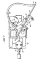
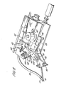
- FIG. 7 and 8 show a further embodiment of the invention.
- the arrangement is generally similar to that described earlier and like parts have been allotted the same reference numeral.
- the embodiment differs in that the probe arm 16 is mounted on the base 10 by a parallel pivoting linkage 40, 41, 42 in place of the simple pivot described earlier.
- the contact face 28 of the probe 17 maintains a constant attitude to the book signatures when rising and falling as they pass beneath it.
- One link 42 of the linkage is pivotally mounted on an axle 43 on the base which extends through the base and carries two angularly spaced arms 44, 45 on the opposite side of the base to the parallel linkage.
- a tension spring 35 is anchored at one end to the arm 45 and at the other end to a lever arm 46 having an adjustable mounting 47 on the base for varying the tension in the spring 35 and therefore varying the downward bias of the probe.
- the other arm 44 is connected by a tether 48 extending round a pulley 49 mounted on the base to an armature 50 of a solenoid 51.
- a control is provided for the solenoid for retracting the armature 50 to draw the tether 48 in a direction to raise the probe 17 away from the path of the signatures into an inoperative position when the probe is not required for use.
- the armature 50 of the solenoid is spring biased outwardly by tension spring 52 to draw the armature outwardly when the solenoid is not energised and thereby allow the probe to fall under the influence of the tension spring 35.
- absolute pressure drops are detected by the system for indicating the passing of a signature below the probe.
- a measuring system can however be provided for detecting the rate of change of air pressure in the air pressure supply to the probe to indicate the passing of a signature below the probe.
Landscapes
- Physics & Mathematics (AREA)
- General Physics & Mathematics (AREA)
- Engineering & Computer Science (AREA)
- Theoretical Computer Science (AREA)
- Measuring Fluid Pressure (AREA)
- Geophysics And Detection Of Objects (AREA)
Applications Claiming Priority (2)
| Application Number | Priority Date | Filing Date | Title |
|---|---|---|---|
| GB8107393 | 1981-03-09 | ||
| GB8107393 | 1981-03-09 |
Publications (1)
| Publication Number | Publication Date |
|---|---|
| EP0060142A1 true EP0060142A1 (fr) | 1982-09-15 |
Family
ID=10520265
Family Applications (1)
| Application Number | Title | Priority Date | Filing Date |
|---|---|---|---|
| EP82301208A Ceased EP0060142A1 (fr) | 1981-03-09 | 1982-03-09 | Détecteur d'approche à pression d'air et appareil de comptage comportant un tel détecteur |
Country Status (3)
| Country | Link |
|---|---|
| US (1) | US4458519A (fr) |
| EP (1) | EP0060142A1 (fr) |
| JP (1) | JPS57211081A (fr) |
Cited By (1)
| Publication number | Priority date | Publication date | Assignee | Title |
|---|---|---|---|---|
| CN103363929A (zh) * | 2013-08-08 | 2013-10-23 | 上海博泽电机有限公司 | 一种减震支撑垫的安装质量检测方法与检测装置 |
Families Citing this family (7)
| Publication number | Priority date | Publication date | Assignee | Title |
|---|---|---|---|---|
| CA2078727A1 (fr) * | 1992-09-21 | 1994-03-22 | Karoly G. Nemeth | Methode et appareil de detection des ecarts d'epaisseur dans des materiaux en feuilles |
| US5814720A (en) * | 1997-02-18 | 1998-09-29 | Visscher; Paul R. | Air pressure sensor control system |
| US5925835A (en) * | 1997-10-13 | 1999-07-20 | Motorola, Inc. | Method of and apparatus for testing a nozzle of a pick-and-place system |
| US7134321B2 (en) * | 2004-07-20 | 2006-11-14 | Asml Holding N.V. | Fluid gauge proximity sensor and method of operating same using a modulated fluid flow |
| US7017390B1 (en) * | 2004-12-07 | 2006-03-28 | Asml Holding N.V. | Proximity sensor nozzle shroud with flow curtain |
| US20070151328A1 (en) * | 2005-12-30 | 2007-07-05 | Asml Holding N.V. | Vacuum driven proximity sensor |
| US7578168B2 (en) * | 2007-06-27 | 2009-08-25 | Asml Holding N.V. | Increasing gas gauge pressure sensitivity using nozzle-face surface roughness |
Citations (4)
| Publication number | Priority date | Publication date | Assignee | Title |
|---|---|---|---|---|
| BE640692A (fr) * | ||||
| DE1275805B (de) * | 1964-11-06 | 1968-08-22 | Plamag Plauener Druckmaschinen | Anordnung zum beruehrungslosen Zaehlen der eine Druckmaschine auf einer Foerderbahn verlassenden Produkte |
| GB1197349A (en) * | 1967-11-04 | 1970-07-01 | Jagenberg Werke Ag | Method and Apparatus for Counting Travelling Overlapping Sheets |
| DE2031679A1 (de) * | 1969-08-26 | 1971-03-11 | Polygraph Leipzig | Vorrichtung zum Zählen der eine Rotationsdruckmaschine in einer Schuppen bahn verlassenden Produkte |
Family Cites Families (12)
| Publication number | Priority date | Publication date | Assignee | Title |
|---|---|---|---|---|
| DE596142C (de) * | 1931-10-29 | 1934-04-27 | Albert Schnellpressen | Vorrichtung zum Abzaehlen von flachen Gegenstaenden, insbesondere Drucksachen |
| US2855150A (en) * | 1955-04-13 | 1958-10-07 | United States Steel Corp | Counting device |
| US3159028A (en) * | 1961-02-15 | 1964-12-01 | Beloit Corp | Sheet break detector |
| CH382477A (de) * | 1961-03-30 | 1964-09-30 | Ferag Ag | Zähleinrichtung |
| US3239676A (en) * | 1962-10-18 | 1966-03-08 | Miehle Goss Dexter Inc | Apparatus for counting overlapping signatures |
| GB1200213A (en) * | 1966-08-19 | 1970-07-29 | Yawata Iron & Steel Co | Fluid gauges |
| US3465777A (en) * | 1968-04-03 | 1969-09-09 | Powers Regulator Co | Fluidic memory element |
| US3702925A (en) * | 1971-07-01 | 1972-11-14 | Electronic Design & Services I | Signature counter |
| US3746841A (en) * | 1971-07-06 | 1973-07-17 | Polygraph Leipzig | Method and apparatus for initiating counting and/or disconnecting processes, in particular for printing presses |
| US3981180A (en) * | 1975-05-01 | 1976-09-21 | Owens-Illinois, Inc. | Apparatus and method for measuring container lean |
| JPS5240767U (fr) * | 1975-09-17 | 1977-03-23 | ||
| US4131140A (en) * | 1977-12-28 | 1978-12-26 | Wylain, Inc. | Automatic fluid dispensing apparatus |
-
1982
- 1982-03-08 US US06/355,483 patent/US4458519A/en not_active Expired - Lifetime
- 1982-03-09 JP JP57037134A patent/JPS57211081A/ja active Pending
- 1982-03-09 EP EP82301208A patent/EP0060142A1/fr not_active Ceased
Patent Citations (4)
| Publication number | Priority date | Publication date | Assignee | Title |
|---|---|---|---|---|
| BE640692A (fr) * | ||||
| DE1275805B (de) * | 1964-11-06 | 1968-08-22 | Plamag Plauener Druckmaschinen | Anordnung zum beruehrungslosen Zaehlen der eine Druckmaschine auf einer Foerderbahn verlassenden Produkte |
| GB1197349A (en) * | 1967-11-04 | 1970-07-01 | Jagenberg Werke Ag | Method and Apparatus for Counting Travelling Overlapping Sheets |
| DE2031679A1 (de) * | 1969-08-26 | 1971-03-11 | Polygraph Leipzig | Vorrichtung zum Zählen der eine Rotationsdruckmaschine in einer Schuppen bahn verlassenden Produkte |
Cited By (2)
| Publication number | Priority date | Publication date | Assignee | Title |
|---|---|---|---|---|
| CN103363929A (zh) * | 2013-08-08 | 2013-10-23 | 上海博泽电机有限公司 | 一种减震支撑垫的安装质量检测方法与检测装置 |
| CN103363929B (zh) * | 2013-08-08 | 2016-08-17 | 上海博泽电机有限公司 | 一种减震支撑垫的安装质量检测方法与检测装置 |
Also Published As
| Publication number | Publication date |
|---|---|
| US4458519A (en) | 1984-07-10 |
| JPS57211081A (en) | 1982-12-24 |
Similar Documents
| Publication | Publication Date | Title |
|---|---|---|
| US3826487A (en) | Control apparatus and method for transporting sheets | |
| US4458519A (en) | Air pressure operated proximity sensor | |
| US3774446A (en) | System for measurement of volume of flow of a flowable granular-like material | |
| AU625580B2 (en) | Mail thickness measuring apparatus | |
| US7297879B2 (en) | Method and apparatus for determining the mass of an article using a load cell | |
| US3430766A (en) | Device for detecting markings and ejecting containers | |
| US5130672A (en) | Apparatus and method for sensing the presence of moving objects | |
| US5017847A (en) | Method and apparatus for adapting the sensitivity of a sensor system for the detection of precipitations during the control of wiping intervals of a screenwiper | |
| GB2104251A (en) | Method and apparatus for controlled feeding of fibre flocks | |
| US4777729A (en) | Thickness measuring apparatus for sheet material | |
| GB2357754A (en) | Detecting double feed or overlap of print media | |
| US4136454A (en) | Apparatus for gauging the thickness of moving laminar material | |
| US4901808A (en) | Device for automatically weighing objects in conveyance | |
| KR890016492A (ko) | 용지 피킹 메카니즘 | |
| JPS61119507A (ja) | 容器コンベア上の渋滞の通報方法とその装置 | |
| GB2094502A (en) | Air pressure sensors | |
| US4868402A (en) | Device for detecting the transit of a mobile member through a reference position | |
| EP0138565A2 (fr) | Machine à clouer | |
| US7568696B2 (en) | Item printing system | |
| EP0054532A2 (fr) | Appareil pour la mesure de la vitesse d'un courant d'une matière en fusion | |
| US4562358A (en) | Electronic pressure responsive switch | |
| US3625509A (en) | Caliper mechanism for lapped sheets fed to a printing press or the like | |
| EP0042860B1 (fr) | Appareil de detection du passage de plusieurs documents | |
| WO2002000361A3 (fr) | Systeme de tri de particules aux caracteristiques differentes | |
| SE8400830L (sv) | Sett och anordning for metning av materialfloden |
Legal Events
| Date | Code | Title | Description |
|---|---|---|---|
| PUAI | Public reference made under article 153(3) epc to a published international application that has entered the european phase |
Free format text: ORIGINAL CODE: 0009012 |
|
| AK | Designated contracting states |
Designated state(s): DE FR IT |
|
| 17P | Request for examination filed |
Effective date: 19820908 |
|
| STAA | Information on the status of an ep patent application or granted ep patent |
Free format text: STATUS: THE APPLICATION HAS BEEN REFUSED |
|
| 18R | Application refused |
Effective date: 19850128 |
|
| RIN1 | Information on inventor provided before grant (corrected) |
Inventor name: LATHAM, KEITH JOSEPH Inventor name: DAY, GEORGE WILLIAM |