EP0060154B1 - Verfahren zur Befestigung eines Griffes an einem Gerät mit einem Zapfen und Vorrichtung zur Durchführung dieses Verfahrens - Google Patents
Verfahren zur Befestigung eines Griffes an einem Gerät mit einem Zapfen und Vorrichtung zur Durchführung dieses Verfahrens Download PDFInfo
- Publication number
- EP0060154B1 EP0060154B1 EP82400210A EP82400210A EP0060154B1 EP 0060154 B1 EP0060154 B1 EP 0060154B1 EP 82400210 A EP82400210 A EP 82400210A EP 82400210 A EP82400210 A EP 82400210A EP 0060154 B1 EP0060154 B1 EP 0060154B1
- Authority
- EP
- European Patent Office
- Prior art keywords
- tube
- tool
- grains
- tang
- accordance
- Prior art date
- Legal status (The legal status is an assumption and is not a legal conclusion. Google has not performed a legal analysis and makes no representation as to the accuracy of the status listed.)
- Expired
Links
- 238000000034 method Methods 0.000 title claims abstract description 23
- 239000000463 material Substances 0.000 claims abstract description 28
- 239000000203 mixture Substances 0.000 claims abstract description 17
- 239000004568 cement Substances 0.000 claims abstract description 15
- 230000006835 compression Effects 0.000 claims abstract 3
- 238000007906 compression Methods 0.000 claims abstract 3
- 239000011347 resin Substances 0.000 claims description 8
- 229920005989 resin Polymers 0.000 claims description 8
- 239000002245 particle Substances 0.000 claims description 7
- 239000002023 wood Substances 0.000 claims description 6
- 239000004576 sand Substances 0.000 claims description 5
- 239000002184 metal Substances 0.000 claims description 4
- 229910052751 metal Inorganic materials 0.000 claims description 4
- 239000010419 fine particle Substances 0.000 claims description 3
- 239000011521 glass Substances 0.000 claims description 3
- 239000004033 plastic Substances 0.000 claims description 3
- 239000010453 quartz Substances 0.000 claims description 3
- VYPSYNLAJGMNEJ-UHFFFAOYSA-N silicon dioxide Inorganic materials O=[Si]=O VYPSYNLAJGMNEJ-UHFFFAOYSA-N 0.000 claims description 3
- 239000000853 adhesive Substances 0.000 claims 1
- 230000001070 adhesive effect Effects 0.000 claims 1
- 239000012634 fragment Substances 0.000 claims 1
- 230000000694 effects Effects 0.000 description 7
- 238000005056 compaction Methods 0.000 description 4
- 238000004519 manufacturing process Methods 0.000 description 4
- 239000004816 latex Substances 0.000 description 2
- 229920000126 latex Polymers 0.000 description 2
- CWYNVVGOOAEACU-UHFFFAOYSA-N Fe2+ Chemical compound [Fe+2] CWYNVVGOOAEACU-UHFFFAOYSA-N 0.000 description 1
- 241000628997 Flos Species 0.000 description 1
- 229910000754 Wrought iron Inorganic materials 0.000 description 1
- 239000011230 binding agent Substances 0.000 description 1
- 230000000903 blocking effect Effects 0.000 description 1
- 238000005520 cutting process Methods 0.000 description 1
- 230000007547 defect Effects 0.000 description 1
- 238000001035 drying Methods 0.000 description 1
- 238000010413 gardening Methods 0.000 description 1
- -1 metallic shot Substances 0.000 description 1
- 238000012986 modification Methods 0.000 description 1
- 230000004048 modification Effects 0.000 description 1
- 238000012856 packing Methods 0.000 description 1
- 238000003825 pressing Methods 0.000 description 1
- 238000005096 rolling process Methods 0.000 description 1
- 238000007789 sealing Methods 0.000 description 1
- XLYOFNOQVPJJNP-UHFFFAOYSA-N water Substances O XLYOFNOQVPJJNP-UHFFFAOYSA-N 0.000 description 1
Images
Classifications
-
- B—PERFORMING OPERATIONS; TRANSPORTING
- B29—WORKING OF PLASTICS; WORKING OF SUBSTANCES IN A PLASTIC STATE IN GENERAL
- B29C—SHAPING OR JOINING OF PLASTICS; SHAPING OF MATERIAL IN A PLASTIC STATE, NOT OTHERWISE PROVIDED FOR; AFTER-TREATMENT OF THE SHAPED PRODUCTS, e.g. REPAIRING
- B29C67/00—Shaping techniques not covered by groups B29C39/00 - B29C65/00, B29C70/00 or B29C73/00
- B29C67/24—Shaping techniques not covered by groups B29C39/00 - B29C65/00, B29C70/00 or B29C73/00 characterised by the choice of material
- B29C67/242—Moulding mineral aggregates bonded with resin, e.g. resin concrete
- B29C67/243—Moulding mineral aggregates bonded with resin, e.g. resin concrete for making articles of definite length
- B29C67/244—Moulding mineral aggregates bonded with resin, e.g. resin concrete for making articles of definite length by vibrating the composition before or during moulding
-
- B—PERFORMING OPERATIONS; TRANSPORTING
- B25—HAND TOOLS; PORTABLE POWER-DRIVEN TOOLS; MANIPULATORS
- B25G—HANDLES FOR HAND IMPLEMENTS
- B25G3/00—Attaching handles to the implements
- B25G3/34—Attaching handles to the implements by pressing the handle on the implements; using cement or molten metal, e.g. casting, moulding, by welding or the like
-
- B—PERFORMING OPERATIONS; TRANSPORTING
- B29—WORKING OF PLASTICS; WORKING OF SUBSTANCES IN A PLASTIC STATE IN GENERAL
- B29C—SHAPING OR JOINING OF PLASTICS; SHAPING OF MATERIAL IN A PLASTIC STATE, NOT OTHERWISE PROVIDED FOR; AFTER-TREATMENT OF THE SHAPED PRODUCTS, e.g. REPAIRING
- B29C70/00—Shaping composites, i.e. plastics material comprising reinforcements, fillers or preformed parts, e.g. inserts
- B29C70/68—Shaping composites, i.e. plastics material comprising reinforcements, fillers or preformed parts, e.g. inserts by incorporating or moulding on preformed parts, e.g. inserts or layers, e.g. foam blocks
- B29C70/84—Shaping composites, i.e. plastics material comprising reinforcements, fillers or preformed parts, e.g. inserts by incorporating or moulding on preformed parts, e.g. inserts or layers, e.g. foam blocks by moulding material on preformed parts to be joined
-
- B—PERFORMING OPERATIONS; TRANSPORTING
- B29—WORKING OF PLASTICS; WORKING OF SUBSTANCES IN A PLASTIC STATE IN GENERAL
- B29L—INDEXING SCHEME ASSOCIATED WITH SUBCLASS B29C, RELATING TO PARTICULAR ARTICLES
- B29L2031/00—Other particular articles
- B29L2031/46—Knobs or handles, push-buttons, grips
- B29L2031/463—Grips, handles
Definitions
- the present invention relates to a method for attaching a handle to a silk tool, such as a fork, spade, rake and the like intended for agriculture or gardening.
- the invention also relates to the device for implementing this method.
- the aforementioned tools include a working member generally made of wrought iron, carrying a shank called silk.
- a working member generally made of wrought iron, carrying a shank called silk.
- the silk of the latter is pressed into the end of a wooden handle, by means of a hydraulic or mechanical press.
- the end of the handle is generally surrounded by a metal socket of suitable shape which is itself covered by a cap.
- the Applicant has improved the aforementioned conventional fixing method, by engaging a rigid tube on the tool tang, keeping the assembly in the correct position by means of an appropriate support and by pouring a resin into the tube to seal the silk to this tube.
- a wooden handle is engaged in the open end of the tube opposite the tool.
- This process provides reliable attachment of the handle to the tool.
- this method has a significant drawback. Indeed, it requires the immobilization of the tool and the tube during the entire duration of the curing of the sealing resin, that is to say for several hours, which considerably slows down the rates of mass production. .
- the object of the present invention is to remedy this drawback.
- a rigid tube is engaged on the tang of the tool, the assembly is held in position by means of a support, a material is introduced into the tube to make the tang integral with the tube and subsequently engaging a handle in the open end of the tube opposite the tool (as in FR-A-2 452 232).
- this process is characterized in that grains of hard material are introduced into the tube, cement is added, the latter being moistened before the mixture is poured into the tube, the assembly constituted by the tube is subjected. and the tool is vibrated in order to produce a compacting of the grains and the tool thus fixed to the tube is then released from the support.
- the grains of hard material are compacted by pressing against each other and against the internal face of the tube and the tang of the tool.
- This compaction of the grains has the effect of making the silk immediately integral with the tube, so that the assembly constituted by the tool fixed to the tube can be immediately released from the support.
- this support immediately becomes available to receive another tool and another tube.
- the method according to the invention is particularly simple to implement, so that it does not require any highly specialized labor.
- the grain size of hard material grains is of particular importance. Indeed, these grains must be fine enough to be able to easily penetrate into the space between the internal face of the tube and the tang of the tool. However, they must be large enough that after compaction they can produce the desired blocking effect.
- these grains are angular, to prevent them from rolling over each other and to allow these grains, after compaction, to hang relative to each other, against the inner face of the tube and the tang. of the tool.
- These grains can be made of any non-friable material, such as quartz, crushed glass, metallic shot, plastic or wood debris and the mixture of these materials.
- the frequency and amplitude of the vibrations applied to the tube and to the tool must be sufficient to produce the desired effect of packing of the grains.
- the Applicant has obtained satisfactory results using a vibration frequency tion between 500 and 30,000 cycles per minute, the amplitude being between 0.5 and 2 mm approximately.
- the invention also relates to the device for implementing the above method.
- This device comprises a support for holding the tool tang engaged in a tube substantially along the axis of the latter and means for introducing inside this tube a material for making the tool tang integral with the tube .
- This device is characterized according to the invention in that it comprises means for applying to the assembly constituted by the tube and the tool vibrations capable of producing a compaction of the aforementioned material, cutting grains of hard material and cement, the latter being moistened before pouring the mixture into the tube.
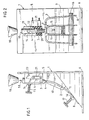
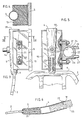
- the device according to the invention comprises a support 1 which holds the floss 3 of the hay fork 2, engaged in a tube 4, substantially along the axis of the latter.
- the support 1 has for this purpose a vertical plate 5 and a horizontal plate 6 forming the base of the device. These two plates 5 and 6 are connected together by an inclined face 7 on which the lower end of the fork 2 rests.
- the upper end 9 of the fork that is to say the base of the latter, rests on a stud 10 fixed to the inclined face 7 and to the vertical plate 5 projecting between the two central teeth 11 of the fork 2.
- the tube 4 axially engaged on the tang 3 of the fork is wedged in a groove 12 flared upwards, formed in a stud 13 fixed to the vertical plate 5, above the lower stud 10.
- the tube 4 is a support against the groove 12 of the stud 13 by means of a buffer 14 urged by elastic means such as a spring 15 or the like.
- the lower end of the fork 2 is in abutment against the inclined face 7 by means of a transverse bar 16 also urged by elastic means such as a spring 17.
- a hopper 19 In line with the open end 18 of the tube 4 is arranged a hopper 19 making it possible to introduce inside the tube 4 a material 20 (see FIG. 2) which will be described in more detail below, intended to render the tang 3 of the fork 2 secured to the tube 4.
- this vibrator comprises a circular cavity 22 enclosing a ball 23.
- this cavity 22 open tangentially, an inlet channel 24 connected to a pipe 25 for supplying pressurized air and an outlet channel 26 connected to an outlet pipe 27.
- the fork 2 is positioned on the support 1.
- the base 9 of this fork 2 is suspended on the lower stud 10 by placing the central branches 11 on either side of this stud.
- the end 8 of the fork teeth is then pressed against the inclined face 7 by means of the support bar 16.
- the tube 4 is then positioned in the groove 12 of the upper stud 13 by threading the lower end of this tube 4 on the tang 3 of the fork 2. It then suffices to press the tube 4 against the stud 13 by means of the support pad 14.
- the material 20 can then be introduced inside the tube 4, by means of the feed hopper 19.
- This material essentially comprises hard and angular grains such as crushed quarz from shards of glass, metallic pebbles and plastic or wood debris.
- These grains have a particle size which is a function of the distance between the tang 3 of the fork and the inner face of the tube 4. This particle size must be sufficiently fine so that the grains can penetrate inside the tube 4 to the bottom of the last.
- the grains of the material 20 are introduced into the tube 4 until the level of this material reaches at least the upper end. silk 3, as shown in figures 2 and 5.
- the amplitude and frequency of these vibrations are a function of the dimensions of the cavity 22 of the vibrator 21, of the mass of the ball 23 and of the air inlet pressure into this cavity.
- the silk 3 is made integral with the tube 4 by means of the grains nested with respect to each other. This effect is reinforced by the angular shape of the grains.
- the frequency of the vibrations applied to the tube 4 and to the fork 2 can vary between 500 and 30,000 cycles per minute and their amplitude between 0.5 and 2 mm approximately.
- the duration of application of these vibrations generally does not exceed 15 seconds.
- the centrifugal force exerted on the ball 23 is 650 Newton at 20,000 rpm.
- the cement can also be added with a water-soluble resin with a latex base such as a resin sold under the name of "Sikalatex". This addition of resin improves the adhesion, flexibility and tightness of the mixture of grains and cement.
- composition of a mixture of grains of sand and cement which has given excellent results.
- Fine sand part by weight
- this mixture is added with water containing in solution a latex-based resin of the aforementioned kind.
- the tang 3 of the fork 2 is immediately made integral with the tube 4, that is to say well before the setting of the cement which generally requires about ten d 'hours.
- the handle 28 can be straight, therefore very economical to manufacture.
- the application of the vibrations to the tube 4 and to the fork 2 can be carried out in another way than by the vibrator 21.
- the Applicant has found that vibrations of sufficient amplitude and frequency were obtained by striking manually the tube 4 with a metal bar or the like.
- the assembly constituted by the tube 4, the fork 2 and the support 1 could also be placed on a vibrating table.
Landscapes
- Engineering & Computer Science (AREA)
- Mechanical Engineering (AREA)
- Ceramic Engineering (AREA)
- Structural Engineering (AREA)
- Chemical & Material Sciences (AREA)
- Composite Materials (AREA)
- Food-Manufacturing Devices (AREA)
- Polishing Bodies And Polishing Tools (AREA)
- Preparation Of Clay, And Manufacture Of Mixtures Containing Clay Or Cement (AREA)
- Table Devices Or Equipment (AREA)
- Adornments (AREA)
- Application Of Or Painting With Fluid Materials (AREA)
- Walking Sticks, Umbrellas, And Fans (AREA)
- Numerical Control (AREA)
- Gear-Shifting Mechanisms (AREA)
- Devices For Post-Treatments, Processing, Supply, Discharge, And Other Processes (AREA)
- Apparatuses For Generation Of Mechanical Vibrations (AREA)
Claims (11)
Priority Applications (1)
| Application Number | Priority Date | Filing Date | Title |
|---|---|---|---|
| AT82400210T ATE8019T1 (de) | 1981-03-11 | 1982-02-05 | Verfahren zur befestigung eines griffes an einem geraet mit einem zapfen und vorrichtung zur durchfuehrung dieses verfahrens. |
Applications Claiming Priority (2)
| Application Number | Priority Date | Filing Date | Title |
|---|---|---|---|
| FR8104819 | 1981-03-11 | ||
| FR8104819A FR2501562A1 (fr) | 1981-03-11 | 1981-03-11 | Procede pour fixer un manche a un outil a soie et dispositif pour sa mise en oeuvre |
Publications (2)
| Publication Number | Publication Date |
|---|---|
| EP0060154A1 EP0060154A1 (de) | 1982-09-15 |
| EP0060154B1 true EP0060154B1 (de) | 1984-06-20 |
Family
ID=9256091
Family Applications (1)
| Application Number | Title | Priority Date | Filing Date |
|---|---|---|---|
| EP82400210A Expired EP0060154B1 (de) | 1981-03-11 | 1982-02-05 | Verfahren zur Befestigung eines Griffes an einem Gerät mit einem Zapfen und Vorrichtung zur Durchführung dieses Verfahrens |
Country Status (6)
| Country | Link |
|---|---|
| EP (1) | EP0060154B1 (de) |
| AT (1) | ATE8019T1 (de) |
| DE (2) | DE60154T1 (de) |
| DK (1) | DK44182A (de) |
| ES (1) | ES8301725A1 (de) |
| FR (1) | FR2501562A1 (de) |
Cited By (1)
| Publication number | Priority date | Publication date | Assignee | Title |
|---|---|---|---|---|
| DE3432461A1 (de) * | 1984-09-04 | 1986-03-13 | Gardena Kress + Kastner Gmbh, 7900 Ulm | Befestigung eines holzstiels |
Families Citing this family (3)
| Publication number | Priority date | Publication date | Assignee | Title |
|---|---|---|---|---|
| US5000611A (en) * | 1988-07-06 | 1991-03-19 | The United States Of America As Represented By The Secretary Of The Air Force | Attachment structure for cylindrical member |
| GB2308374A (en) * | 1995-12-19 | 1997-06-25 | Nat Starch Chem Corp | Fillers for strengthening structures |
| BE1010728A3 (fr) * | 1996-10-31 | 1998-12-01 | Donck Daniel | Piece d'equipement. |
Family Cites Families (5)
| Publication number | Priority date | Publication date | Assignee | Title |
|---|---|---|---|---|
| FR588473A (fr) * | 1924-07-04 | 1925-05-07 | Patent Besteck Fabrik G M B H | Procédé et appareil de fixation de queue ou de soie d'instruments, outils et objets analogues dans des poignées ou manches en métal |
| GB971619A (en) * | 1960-07-08 | 1964-09-30 | B G Fabricates Ltd | Improvements in or relating to methods of making imitation stone slabs |
| FR2088773A5 (en) * | 1970-04-23 | 1972-01-07 | Dannes Lavocat Ciments | Composite synthetic building panels - esp of polyester reinforced with aggregate |
| DE2807681A1 (de) * | 1978-02-23 | 1979-08-30 | Werner Gieb | Verfahren und vorrichtung zum herstellen von verkleidungsplatten, waenden, bausteinen, formstuecken u.dgl. |
| FR2452232A3 (fr) * | 1979-03-29 | 1980-10-24 | Gouvy Et Cie | Procede pour fixer un manche a un outil a soie, et outil a soie s'y rapportant |
-
1981
- 1981-03-11 FR FR8104819A patent/FR2501562A1/fr active Granted
-
1982
- 1982-02-01 DK DK44182A patent/DK44182A/da not_active Application Discontinuation
- 1982-02-04 ES ES509327A patent/ES8301725A1/es not_active Expired
- 1982-02-05 DE DE198282400210T patent/DE60154T1/de active Pending
- 1982-02-05 DE DE8282400210T patent/DE3260259D1/de not_active Expired
- 1982-02-05 AT AT82400210T patent/ATE8019T1/de not_active IP Right Cessation
- 1982-02-05 EP EP82400210A patent/EP0060154B1/de not_active Expired
Cited By (1)
| Publication number | Priority date | Publication date | Assignee | Title |
|---|---|---|---|---|
| DE3432461A1 (de) * | 1984-09-04 | 1986-03-13 | Gardena Kress + Kastner Gmbh, 7900 Ulm | Befestigung eines holzstiels |
Also Published As
| Publication number | Publication date |
|---|---|
| ATE8019T1 (de) | 1984-07-15 |
| DE3260259D1 (en) | 1984-07-26 |
| DE60154T1 (de) | 1983-01-05 |
| DK44182A (da) | 1982-09-12 |
| ES509327A0 (es) | 1982-12-16 |
| FR2501562A1 (fr) | 1982-09-17 |
| FR2501562B1 (de) | 1983-05-06 |
| EP0060154A1 (de) | 1982-09-15 |
| ES8301725A1 (es) | 1982-12-16 |
Similar Documents
| Publication | Publication Date | Title |
|---|---|---|
| BE1008917A3 (fr) | Outil abrasif, de coupe ou analogue et procede de fabrication de cet outil. | |
| FR2625114A1 (fr) | Support de bout rapporte pour concasseur et procede de preparation d'un tel support | |
| EP0060154B1 (de) | Verfahren zur Befestigung eines Griffes an einem Gerät mit einem Zapfen und Vorrichtung zur Durchführung dieses Verfahrens | |
| EP2361169A1 (de) | Mehrzweckschlagwerkzeug mit einem mechanismus zur aufnahme der auf das greifmittel übertragenen energie | |
| FR2963269A1 (fr) | Dispositif d'extraction et d'insertion d'une goupille, procedes d'extraction et d'insertion associes | |
| WO1992010344A1 (fr) | Materiau de construction obtenu a partir de residus vegetaux et son procede d'obtention | |
| FR2529488A1 (fr) | Embrayage a friction monte par rivetage des ressorts a lames avec le plateau de pression, et procede de rivetage correspondant | |
| EP0129531B1 (de) | Verfahren und Mittel zur Ausführung einer Prothese | |
| CA2912781A1 (fr) | Dispositif de recuperation de la substance aqueuse d'un arbre et procede pour sa mise en oeuvre dans le gemmage | |
| BE546957A (de) | ||
| CN112424426B (zh) | 磨损件、铲斗、系统以及方法 | |
| FR2672982A1 (fr) | Procede et dispositif d'amorcage d'etuis de munitions ou de charges de scellement a percussion annulaire. | |
| FR2954673A1 (fr) | Rotor de machine a reduire des vegetaux | |
| EP1604065A1 (de) | Verfahren zur wiedereinsetzung einer auf einer holzschwelle eingesetzten schienenverankerung und einlage zur durchführung des verfahrens | |
| EP0038293B1 (de) | Verfahren zur Fixierung von Asten in einem Brett und Brett mit fixierten Asten | |
| EP0098756A1 (de) | Schwingungsübertragungsstück mit schwimmendem Kern | |
| FR2546740A1 (fr) | Appareil pour le descellement des elements prothetiques | |
| CN119744732B (zh) | 一种园林树苗移栽铁锹 | |
| BE560289A (de) | ||
| EP2323825B1 (de) | Verfahren zur herstellung eines kerns mit einer hülle beinhaltend granulat- und/oder pulverförmige produkte, vorrichtung und hergestellter kern. | |
| FR3158113A1 (fr) | Accessoire pour appareil électroportatif | |
| WO2012032009A1 (fr) | Chaine de haveuse a roche et haveuse | |
| FR2600929A1 (fr) | Procede de fixation de tetes de travail sur des outils de decoupe ou de raclage, en particulier sur des ciseaux de tournage du bois. | |
| FR2799145A3 (fr) | Scie abrasive | |
| FR2856611A1 (fr) | Procede de broyage de grains ou analogues et moyens de mise en oeuvre |
Legal Events
| Date | Code | Title | Description |
|---|---|---|---|
| PUAI | Public reference made under article 153(3) epc to a published international application that has entered the european phase |
Free format text: ORIGINAL CODE: 0009012 |
|
| 17P | Request for examination filed |
Effective date: 19820210 |
|
| AK | Designated contracting states |
Designated state(s): AT BE CH DE GB IT LU NL SE |
|
| TCAT | At: translation of patent claims filed | ||
| ITCL | It: translation for ep claims filed |
Representative=s name: BARZANO' E ZANARDO ROMA S.P.A. |
|
| TCNL | Nl: translation of patent claims filed | ||
| DET | De: translation of patent claims | ||
| ITF | It: translation for a ep patent filed | ||
| GRAA | (expected) grant |
Free format text: ORIGINAL CODE: 0009210 |
|
| AK | Designated contracting states |
Designated state(s): AT BE CH DE GB IT LI LU NL SE |
|
| REF | Corresponds to: |
Ref document number: 8019 Country of ref document: AT Date of ref document: 19840715 Kind code of ref document: T |
|
| REF | Corresponds to: |
Ref document number: 3260259 Country of ref document: DE Date of ref document: 19840726 |
|
| PG25 | Lapsed in a contracting state [announced via postgrant information from national office to epo] |
Ref country code: LU Free format text: LAPSE BECAUSE OF NON-PAYMENT OF DUE FEES Effective date: 19850228 |
|
| PLBE | No opposition filed within time limit |
Free format text: ORIGINAL CODE: 0009261 |
|
| STAA | Information on the status of an ep patent application or granted ep patent |
Free format text: STATUS: NO OPPOSITION FILED WITHIN TIME LIMIT |
|
| 26N | No opposition filed | ||
| PGFP | Annual fee paid to national office [announced via postgrant information from national office to epo] |
Ref country code: LU Payment date: 19860115 Year of fee payment: 5 |
|
| PGFP | Annual fee paid to national office [announced via postgrant information from national office to epo] |
Ref country code: NL Payment date: 19860228 Year of fee payment: 5 |
|
| PG25 | Lapsed in a contracting state [announced via postgrant information from national office to epo] |
Ref country code: LI Effective date: 19870228 Ref country code: CH Effective date: 19870228 |
|
| BERE | Be: lapsed |
Owner name: GOUVY & CIE S.A. Effective date: 19870228 |
|
| PG25 | Lapsed in a contracting state [announced via postgrant information from national office to epo] |
Ref country code: NL Effective date: 19870901 |
|
| NLV4 | Nl: lapsed or anulled due to non-payment of the annual fee | ||
| REG | Reference to a national code |
Ref country code: CH Ref legal event code: PL |
|
| PG25 | Lapsed in a contracting state [announced via postgrant information from national office to epo] |
Ref country code: BE Effective date: 19890228 |
|
| PGFP | Annual fee paid to national office [announced via postgrant information from national office to epo] |
Ref country code: SE Payment date: 19920108 Year of fee payment: 11 |
|
| PGFP | Annual fee paid to national office [announced via postgrant information from national office to epo] |
Ref country code: AT Payment date: 19920121 Year of fee payment: 11 |
|
| PGFP | Annual fee paid to national office [announced via postgrant information from national office to epo] |
Ref country code: GB Payment date: 19920123 Year of fee payment: 11 |
|
| ITTA | It: last paid annual fee | ||
| PGFP | Annual fee paid to national office [announced via postgrant information from national office to epo] |
Ref country code: DE Payment date: 19920311 Year of fee payment: 11 |
|
| PG25 | Lapsed in a contracting state [announced via postgrant information from national office to epo] |
Ref country code: GB Effective date: 19930205 Ref country code: AT Effective date: 19930205 |
|
| PG25 | Lapsed in a contracting state [announced via postgrant information from national office to epo] |
Ref country code: SE Effective date: 19930206 |
|
| GBPC | Gb: european patent ceased through non-payment of renewal fee |
Effective date: 19930205 |
|
| PG25 | Lapsed in a contracting state [announced via postgrant information from national office to epo] |
Ref country code: DE Effective date: 19931103 |
|
| EUG | Se: european patent has lapsed |
Ref document number: 82400210.9 Effective date: 19930912 |