EP0060197B1 - Rodoir à granulométrie variable - Google Patents
Rodoir à granulométrie variable Download PDFInfo
- Publication number
- EP0060197B1 EP0060197B1 EP82400395A EP82400395A EP0060197B1 EP 0060197 B1 EP0060197 B1 EP 0060197B1 EP 82400395 A EP82400395 A EP 82400395A EP 82400395 A EP82400395 A EP 82400395A EP 0060197 B1 EP0060197 B1 EP 0060197B1
- Authority
- EP
- European Patent Office
- Prior art keywords
- ring
- flutes
- male
- grinder
- female
- Prior art date
- Legal status (The legal status is an assumption and is not a legal conclusion. Google has not performed a legal analysis and makes no representation as to the accuracy of the status listed.)
- Expired
Links
- 238000001033 granulometry Methods 0.000 title 1
- 229910003460 diamond Inorganic materials 0.000 description 6
- 239000010432 diamond Substances 0.000 description 6
- 238000010009 beating Methods 0.000 description 1
- 125000006850 spacer group Chemical group 0.000 description 1
Images

Classifications
-
- B—PERFORMING OPERATIONS; TRANSPORTING
- B24—GRINDING; POLISHING
- B24B—MACHINES, DEVICES, OR PROCESSES FOR GRINDING OR POLISHING; DRESSING OR CONDITIONING OF ABRADING SURFACES; FEEDING OF GRINDING, POLISHING, OR LAPPING AGENTS
- B24B33/00—Honing machines or devices; Accessories therefor
- B24B33/08—Honing tools
- B24B33/085—Honing tools in which the honing element consists of a deformable body
Definitions
- EP-A-0 005 003 discloses expandable lappers comprising externally grooved abrasive rings which can be deformed by crushing.
- the present invention relates to a lapping machine of the above type in which the abrasive ring deforms while remaining perfectly cylindrical, which results in better lapping precision.
- the lapping according to the invention is characterized in that the pushers are in abutment against male internal grooves of the ring, in that the expansion cone is held from place to place in the axis of the body by centralizers arranged in mortises formed at the periphery of the cone, and in that the ring has external grooves distributed uniformly over its periphery, the external female grooves being arranged opposite the internal male grooves and being deep enough for the wall existing between a female groove outer and an inner male groove is thin enough to give the ring the flexibility it needs to expand.
- the abrasive ring can have twice as many internal male and female grooves as external male and female grooves.
- the lapping may comprise at the right of each ring, as many pushers as there are male grooves or external female grooves, each of them being in contact with an internal male groove situated opposite an external male groove.
- the abrasive ring can also include an equal number of internal grooves and external grooves, each internal male groove being arranged opposite an external female groove.
- the lapping may comprise, in line with the ring, pushers in a number equal to half the number of male grooves or female grooves, each of them being in contact with an internal male groove.
- the lapping comprises on the side of its free end at least one fixing ring coaxial with a ring with ramps which is integral with the expansion cone, has a cylindrical outer surface in contact with the wall of the central bore of the lapping body, and is provided with sloping grooves in which are engaged expansion pushers.
- the lapping according to the invention comprises a body or mandrel 1 having a cylindrical bore 2 inside which can slide an expansion cone 3.
- This cone is held in place in place in the axis of the body 1 by centralizers 4 which are glued in mortises 5 formed at the periphery of the cone.
- centralizers 4 which are glued in mortises 5 formed at the periphery of the cone.
- three series of mortises are provided axially separated from each other, each series comprising four mortises distributed circumferentially around the cone.
- a pin 6 crosses a hole provided axially at one end of the body 1 and is engaged in a groove 7 of the cone 3, which secures in rotation the cone and the body while allowing the cone to move axially in the body .
- the reference 8 designates a nozzle screwed into the end of the large section of the cone and which is intended to be connected to the expansion rod, not shown, of a lapping machine.
- a spacer 9 On the body 1 are mounted a spacer 9 and a series of diamond rings 10.
- Each of the rings 10 is fluted internally and externally. More specifically, it internally comprises 2n male splines alternately 11a and 11b equidistant and separated from each other by female splines 12, slightly narrower than the male splines. Externally, it comprises n female splines 13 arranged opposite the internal male splines 11a and separated from each other by male splines 14. These female splines 13 have a width less than that of the splines 11a and are relatively deep so that the ring has a reduced thickness at the right of these grooves 11a, which gives it a certain flexibility and allows its extension.
- the body 1 of the lapping has on its periphery 2n grooves 16 which extend over practically its entire length. In these grooves open openings. 17 whose length is substantially equal to that of the rings 10 and which are spaced from each other by a distance equal to this same length; these openings 17 are staggered.
- the rings 10 are mounted on the body 1 having their internal male splines 11a and 11b engaged in the splines of the body 1, so that the splines 11 are located opposite the openings 17 of these splines 16.
- Pushers 18 engaged in these openings are arranged between the male splines 11b and the expansion cone 3; the inner face of these pushers has the same slope as the cone; due to the staggered arrangement of the openings 17, the angular positions of the rings 10 differ from one ring to the other by 360 ° / 2n.
- a ring 19 is fitted onto a tie rod 20 fixed to the end of the expansion cone 3 and held in place by a nut 21.
- Finished diamond rings 10a are mounted on the body 1, in line with the ring 19, being separated from the rings 10 by a ring 22; the set of diamond rings 10 and 10a is held on the body by a nut 23.
- the ring 19 has non-opening longitudinal slots 24 and external grooves 25 with a sloping bottom, in which the pushers 18a are engaged, the underside of these pushers having the same slope as the bottom of the grooves 25.
- this lapper To use this lapper, it is engaged deflated in the bore to be machined. During the beating of the spindle, only the rings 10 are in contact with the wall of the bore. When the expansion cylinder controlling the expansion rod of the lapping machine is in abutment, the movement of the spindle is stopped while the latter is in the high position and the lapping rod is extracted from the bore; the rings 10a finish the bore.
- fluted diamond rings 10 comprising twice as many external grooves as internal grooves
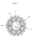
- fluted diamond rings 26 comprising as many internal grooves as external grooves (FIG. 5).
- the pushers are in contact with parts of reduced thickness of the ring.
Landscapes
- Engineering & Computer Science (AREA)
- Mechanical Engineering (AREA)
- Finish Polishing, Edge Sharpening, And Grinding By Specific Grinding Devices (AREA)
Description
- On connaît, par le brevet EP-A-0 005 003 des rodoirs expansibles comportant des bagues abrasives cannelées extérieurement et déformables par écrasement.
- On connaît par ailleurs par le brevet FR-A-2 356 479 des rodoirs expansibles pour machines à roder comprenant au moins une bague abrasive élastique et déformable, par exemple diamantée, cannelée intérieurement, et qui est montée sur un corps ou mandrin, ce dernier comportant un alésage central dans lequel est monté mobile axialement un cône d'expansion propre à déformer la bague par l'intermédiaire de poussoirs mobiles radialement dans le corps.
- Dans les rodoirs de ce genre actuellement réalisés, les bagues abrasives sont fendues. Or l'expérience montre que ces bagues abrasives se déforment en tonneaux.
- La présente invention a pour objet un rodoir du type ci-dessus dans lequel la bague abrasive se déforme en restant parfaitement cylindrique, ce qui entraîne une meilleure précision de rodage.
- Le rodoir selon l'invention est caractérisé en ce que les poussoirs sont en appui contre des cannelures intérieures mâles de la bague, en ce que le cône d'expansion est maintenu de place en place dans l'axe du corps par des centreurs disposés dans des mortaises ménagées à la périphérie du cône, et en ce que la bague comporte des cannelures extérieures distribuées uniformément sur sa périphérie, les cannelures femelles extérieures étant disposées en regard des cannelures mâles intérieures et étant suffisamment profondes pour que la paroi existant entre une cannelure femelle extérieure et une cannelure mâle intérieure soit suffisamment mince pour donner à la bague la souplesse nécessaire à son expansion.
- La bague abrasive peut comporter deux fois plus de cannelures mâles et femelles intérieures que de cannelures mâles et femelles extérieures.
- Le rodoir peut comporter au droit de chaque bague, autant de poussoirs qu'il existe de cannelures mâles ou de cannelures femelles extérieures, chacun d'eux se trouvant au contact d'une cannelure mâle intérieure située en regard d'une cannelure mâle extérieure.
- La bague abrasive peut également comporter un nombre égal de cannelures intérieures et de cannelures extérieures, chaque cannelure mâle intérieure étant disposée en regard d'une cannelure femelle extérieure. Dans ce cas, le rodoir peut comporter, au droit de la bague, des poussoirs en nombre égal à la moitié du nombre des cannelures mâles ou des cannelures femelles, chacun d'eux se trouvant au contact d'une cannelure mâle intérieure.
- Dans un mode de réalisation avantageux de l'invention, le rodoir comporte du côté de son extrémité libre au moins une bague de fixation coaxiale à une bague à rampes qui est solidaire du cône d'expansion, présente une surface extérieure cylindrique au contact de la paroi de l'alésage central du corps du rodoir, et est munie de rainures en pente dans lesquelles sont engagées des poussoirs d'expansion.
- On a décrit ci-après, à titre d'exemples non limitatifs, divers modes de réalisation du rodoir selon l'invention, avec référence aux dessins annexés dans lesquels :
- La Figure 1 est une vue en coupe axiale d'un premier mode de réalisation du rodoir,
- La Figure 2 en est une coupe transversale suivant II-II de la Figure 1,
- La Figure 3 en est une coupe transversale suivant III-III de la Figure 1,
- La Figure 4 en est une coupe transversale suivant IV-IV de la Figure 1,
- La Figure 5 est une coupe transversale montrant un autre type de bague expansible.
- Tel qu'il est représenté aux Figures 1 à 4, le rodoir selon l'invention comprend un corps ou mandrin 1 comportant un alésage cylindrique 2 à l'intérieur duquel peut coulisser un cône d'expansion 3. Ce cône est maintenu de place en place dans l'axe du corps 1 par des centreurs 4 qui sont collés dans des mortaises 5 ménagées à la périphérie du cône. Dans l'exemple représenté, il est prévu trois séries de mortaises séparées axialement les unes des autres chaque série comportant quatre mortaises réparties circonférentielle- ment autour du cône. Un pion 6 traverse un trou prévu axialement à l'une des extrémités du corps 1 et est engagé dans une rainure 7 du cône 3, ce qui solidarise en rotation le cône et le corps tout en permettant au cône de se déplacer axialement dans le corps. La référence 8 désigne un embout vissé dans l'extrémité de grande section du cône et qui est destiné à être relié à la tige d'expansion, non représentée, d'une machine à roder.
- Sur le corps 1 sont montées une entretoise 9 et une série de bagues diamantées 10.
- Chacune des bagues 10 est cannelée intérieurement et extérieurement. De manière plus précise, elle comporte intérieurement 2n cannelures mâles alternativement 11a et 11b équidistantes et séparées les unes des autres par des cannelures femelles 12, légèrement plus étroites que les cannelures mâles. Extérieurement, elle comporte n cannelures femelles 13 disposées en regard des cannelures mâles intérieures 11a et séparées les unes des autres par des cannelures mâles 14. Ces cannelures femelles 13 ont une largeur inférieure à celle des cannelures 11a et sont relativement profondes de sorte que la bague présente une épaisseur réduite au droit de ces cannelures 11a, ce qui lui donne une certaine souplesse et permet son extension.
- Le corps 1 du rodoir comporte sur sa périphérie 2n cannelures 16 qui s'étendent sur pratiquement toute sa longueur. Dans ces cannelures débouchent des ouvertures.17 dont la longueur est sensiblement égale à celle des bagues 10 et qui sont écartées les unes des autres d'une distance égale à cette même longueur ; ces ouvertures 17 sont disposées en quinconce.
- Les bagues 10 sont montées sur le corps 1 en ayant leurs cannelures mâles intérieures 11a et 11b engagées dans les cannelures du corps 1, de façon que les cannelures 11 se trouvent en regard des ouvertures 17 de ces cannelures 16. Des poussoirs 18 engagés dans ces ouvertures sont disposés entre les cannelures mâles 11 b et le cône d'expansion 3 ; la face intérieure de ces poussoirs a même pente que le cône ; du fait de la disposition en quinconce des ouvertures 17, les positions angulaires des bagues 10 diffèrent d'une bague à l'autre de 360°/2n.
- Une bague 19 est emmanchée sur un tirant 20 fixé à l'extrémité du cône d'expansion 3 et maintenue en place par un écrou 21. Des bagues diamantées de finition 10a, de même constitution que les bagues de travail 10, mais d'un diamètre et d'une finesse plus grands, sont montées sur le corps 1, au droit de la bague 19, en étant séparées des bagues 10 par une bague 22 ; l'ensemble des bagues diamantées 10 et 10a est maintenu sur le corps par un écrou 23. La bague 19 comporte des fentes longitudinales non débouchantes 24 et des rainures extérieures 25 à fond penté, dans lesquelles sont engagées des poussoirs 18a, la face inférieure de ces poussoirs présentant la même pente que le fond des rainures 25.
- Pour utiliser ce rodoir, on l'engage dégonflé dans l'alésage à usiner. Lors du battement de la broche, seules les bagues 10 sont en contact de la paroi de l'alésage. Lorsque le vérin d'expansion commandant la tige d'expansion de la machine à roder est en butée, on arrête le mouvement de la broche alors que celle-ci est en position haute et on extrait le rodoir de l'alésage ; les bagues 10a finissent l'alésage.
- Au lieu d'utiliser des bagues diamantées cannelées 10 comportant deux fois plus de cannelures extérieures que de cannelures intérieures, on peut employer des bagues diamantées cannelées 26 comportant autant de cannelures intérieures que de cannelures extérieures (Figure 5). Dans ce cas, les poussoirs se trouvent au contact de parties d'épaisseur réduite de la bague.
Claims (7)
Applications Claiming Priority (2)
| Application Number | Priority Date | Filing Date | Title |
|---|---|---|---|
| FR8105258 | 1981-03-11 | ||
| FR8105258A FR2501561A1 (fr) | 1981-03-11 | 1981-03-11 | Rodoir a granulometrie variable |
Publications (2)
| Publication Number | Publication Date |
|---|---|
| EP0060197A1 EP0060197A1 (fr) | 1982-09-15 |
| EP0060197B1 true EP0060197B1 (fr) | 1984-07-25 |
Family
ID=9256296
Family Applications (1)
| Application Number | Title | Priority Date | Filing Date |
|---|---|---|---|
| EP82400395A Expired EP0060197B1 (fr) | 1981-03-11 | 1982-03-08 | Rodoir à granulométrie variable |
Country Status (3)
| Country | Link |
|---|---|
| EP (1) | EP0060197B1 (fr) |
| DE (1) | DE3260429D1 (fr) |
| FR (1) | FR2501561A1 (fr) |
Families Citing this family (3)
| Publication number | Priority date | Publication date | Assignee | Title |
|---|---|---|---|---|
| US5390448A (en) * | 1993-04-22 | 1995-02-21 | Sunnen Products Company | Modular expandable honing tool |
| JP5294945B2 (ja) | 2009-03-31 | 2013-09-18 | 本田技研工業株式会社 | 内径加工工具 |
| CN116237826B (zh) * | 2023-05-11 | 2023-07-14 | 四川省卓辰精密机械制造有限公司 | 一种阀块油孔打磨工具及打磨装置 |
Citations (1)
| Publication number | Priority date | Publication date | Assignee | Title |
|---|---|---|---|---|
| EP0005003A1 (fr) * | 1978-04-19 | 1979-10-31 | Ex-Cell-O Corporation | Outil abrasif expansible |
Family Cites Families (2)
| Publication number | Priority date | Publication date | Assignee | Title |
|---|---|---|---|---|
| DE2460997C3 (de) * | 1974-12-21 | 1984-01-26 | Nagel Maschinen- und Werkzeugfabrik GmbH, 7440 Nürtingen | Honwerkzeug zur Bearbeitung zylindrischer Werkstückbohrungen |
| FR2356479A1 (fr) * | 1976-06-28 | 1978-01-27 | Citroen Sa | Rodoir a bague deformable |
-
1981
- 1981-03-11 FR FR8105258A patent/FR2501561A1/fr active Granted
-
1982
- 1982-03-08 EP EP82400395A patent/EP0060197B1/fr not_active Expired
- 1982-03-08 DE DE8282400395T patent/DE3260429D1/de not_active Expired
Patent Citations (1)
| Publication number | Priority date | Publication date | Assignee | Title |
|---|---|---|---|---|
| EP0005003A1 (fr) * | 1978-04-19 | 1979-10-31 | Ex-Cell-O Corporation | Outil abrasif expansible |
Also Published As
| Publication number | Publication date |
|---|---|
| FR2501561B1 (fr) | 1985-01-11 |
| EP0060197A1 (fr) | 1982-09-15 |
| DE3260429D1 (en) | 1984-08-30 |
| FR2501561A1 (fr) | 1982-09-17 |
Similar Documents
| Publication | Publication Date | Title |
|---|---|---|
| EP0944765B1 (fr) | Outil de forage et/ou de carottage | |
| FR2929868A1 (fr) | Porte-outil pourvu d'un moyen d'amortissement | |
| FR2538442A1 (fr) | Taillant pour foration rotative assistee par jet | |
| EP1225322A1 (fr) | Dispositif de centrage d'un tube dans un arbre de turbine | |
| FR2620960A1 (fr) | Outil de honage ou de pierrage expansible | |
| FR2704168A1 (fr) | Mandrin de honage expansible modulaire. | |
| EP0063976B1 (fr) | Rodoir à barrettes | |
| EP0130592B1 (fr) | Plaquette de coupe pour usinage par rotation, outil garni de telles plaquettes et procédé d'affûtage de telles plaquettes | |
| EP0060197B1 (fr) | Rodoir à granulométrie variable | |
| EP3600736B1 (fr) | Mandrin de serrage a coulisseaux inclines | |
| CA2918614A1 (fr) | Outil de rodage d'une surface externe d'un tube cylindrique droit | |
| EP1737597A1 (fr) | Plaquette de coupe a nombre limite de faces de cadrage | |
| FR2704790A1 (fr) | Scie-cloche réglable de diamètre variable. | |
| FR2686538A1 (fr) | Mandrin de honage. | |
| FR2741560A1 (fr) | Meule perfectionnee pour verres ophtalmiques, et machine de meulage correspondante | |
| FR2517576A1 (fr) | ||
| FR2687087A1 (fr) | Tete de honage avec avance en spirale. | |
| EP3608060B1 (fr) | Outil d'usinage pour meuler une piece | |
| EP0661136B1 (fr) | Procédé de rodage de la surface d'une pièce et rodoir pour la mise en oeuvre de ce procédé | |
| FR2515547A1 (fr) | Outil abrasif a une seule passe a diametre fixe pour usinage d'un alesage par rotation et mouvement axial | |
| EP2688703B1 (fr) | Procede et dispositif de fraisage - surfacage | |
| FR2632217A1 (fr) | Dispositif et procede de fabrication d'une poulie a gorge a partir d'un disque circulaire en tole | |
| FR2551833A1 (fr) | Appareil destine au montage d'un organe sur une canalisation | |
| FR2650207A1 (fr) | Dispositif de fraisage au profil auto-adaptable | |
| FR2523489A1 (fr) | Barre d'alesage |
Legal Events
| Date | Code | Title | Description |
|---|---|---|---|
| PUAI | Public reference made under article 153(3) epc to a published international application that has entered the european phase |
Free format text: ORIGINAL CODE: 0009012 |
|
| AK | Designated contracting states |
Designated state(s): DE GB IT |
|
| 17P | Request for examination filed |
Effective date: 19820920 |
|
| ITF | It: translation for a ep patent filed | ||
| GRAA | (expected) grant |
Free format text: ORIGINAL CODE: 0009210 |
|
| AK | Designated contracting states |
Designated state(s): DE GB IT |
|
| REF | Corresponds to: |
Ref document number: 3260429 Country of ref document: DE Date of ref document: 19840830 |
|
| PLBE | No opposition filed within time limit |
Free format text: ORIGINAL CODE: 0009261 |
|
| STAA | Information on the status of an ep patent application or granted ep patent |
Free format text: STATUS: NO OPPOSITION FILED WITHIN TIME LIMIT |
|
| ITPR | It: changes in ownership of a european patent |
Owner name: OFFERTA DI LICENZA AL PUBBLICO |
|
| 26N | No opposition filed | ||
| ITTA | It: last paid annual fee | ||
| PGFP | Annual fee paid to national office [announced via postgrant information from national office to epo] |
Ref country code: GB Payment date: 20000322 Year of fee payment: 19 |
|
| PGFP | Annual fee paid to national office [announced via postgrant information from national office to epo] |
Ref country code: DE Payment date: 20000530 Year of fee payment: 19 |
|
| PG25 | Lapsed in a contracting state [announced via postgrant information from national office to epo] |
Ref country code: GB Free format text: LAPSE BECAUSE OF NON-PAYMENT OF DUE FEES Effective date: 20010308 |
|
| PG25 | Lapsed in a contracting state [announced via postgrant information from national office to epo] |
Ref country code: DE Free format text: LAPSE BECAUSE OF NON-PAYMENT OF DUE FEES Effective date: 20010331 |
|
| GBPC | Gb: european patent ceased through non-payment of renewal fee |
Effective date: 20010308 |