EP0060209B1 - Gelände- und Amphibienmotorfahrzeug - Google Patents
Gelände- und Amphibienmotorfahrzeug Download PDFInfo
- Publication number
- EP0060209B1 EP0060209B1 EP82440005A EP82440005A EP0060209B1 EP 0060209 B1 EP0060209 B1 EP 0060209B1 EP 82440005 A EP82440005 A EP 82440005A EP 82440005 A EP82440005 A EP 82440005A EP 0060209 B1 EP0060209 B1 EP 0060209B1
- Authority
- EP
- European Patent Office
- Prior art keywords
- wheels
- vehicle
- caterpillars
- axles
- vehicle according
- Prior art date
- Legal status (The legal status is an assumption and is not a legal conclusion. Google has not performed a legal analysis and makes no representation as to the accuracy of the status listed.)
- Expired
Links
Images


Classifications
-
- B—PERFORMING OPERATIONS; TRANSPORTING
- B60—VEHICLES IN GENERAL
- B60F—VEHICLES FOR USE BOTH ON RAIL AND ON ROAD; VEHICLES CAPABLE OF TRAVELLING IN OR ON DIFFERENT MEDIA, e.g. AMPHIBIOUS VEHICLES
- B60F3/00—Amphibious vehicles, i.e. vehicles capable of travelling both on land and on water; Land vehicles capable of travelling under water
-
- B—PERFORMING OPERATIONS; TRANSPORTING
- B62—LAND VEHICLES FOR TRAVELLING OTHERWISE THAN ON RAILS
- B62D—MOTOR VEHICLES; TRAILERS
- B62D53/00—Tractor-trailer combinations; Road trains
- B62D53/02—Tractor-trailer combinations; Road trains comprising a uniaxle tractor unit and a uniaxle trailer unit
-
- B—PERFORMING OPERATIONS; TRANSPORTING
- B62—LAND VEHICLES FOR TRAVELLING OTHERWISE THAN ON RAILS
- B62D—MOTOR VEHICLES; TRAILERS
- B62D55/00—Endless track vehicles
- B62D55/04—Endless track vehicles with tracks and alternative ground wheels, e.g. changeable from endless track vehicle into wheeled vehicle and vice versa
-
- B—PERFORMING OPERATIONS; TRANSPORTING
- B62—LAND VEHICLES FOR TRAVELLING OTHERWISE THAN ON RAILS
- B62D—MOTOR VEHICLES; TRAILERS
- B62D61/00—Motor vehicles or trailers, characterised by the arrangement or number of wheels, not otherwise provided for, e.g. four wheels in diamond pattern
- B62D61/12—Motor vehicles or trailers, characterised by the arrangement or number of wheels, not otherwise provided for, e.g. four wheels in diamond pattern with variable number of ground engaging wheels, e.g. with some wheels arranged higher than others, or with retractable wheels
-
- F—MECHANICAL ENGINEERING; LIGHTING; HEATING; WEAPONS; BLASTING
- F16—ENGINEERING ELEMENTS AND UNITS; GENERAL MEASURES FOR PRODUCING AND MAINTAINING EFFECTIVE FUNCTIONING OF MACHINES OR INSTALLATIONS; THERMAL INSULATION IN GENERAL
- F16F—SPRINGS; SHOCK-ABSORBERS; MEANS FOR DAMPING VIBRATION
- F16F7/00—Vibration-dampers; Shock-absorbers
- F16F7/10—Vibration-dampers; Shock-absorbers using inertia effect
- F16F7/104—Vibration-dampers; Shock-absorbers using inertia effect the inertia member being resiliently mounted
-
- B—PERFORMING OPERATIONS; TRANSPORTING
- B60—VEHICLES IN GENERAL
- B60G—VEHICLE SUSPENSION ARRANGEMENTS
- B60G2300/00—Indexing codes relating to the type of vehicle
- B60G2300/07—Off-road vehicles
Definitions
- the present invention relates to the field of the construction of motor vehicles, in particular special vehicles such as all-terrain and / or amphibious vehicles, and relates to such a vehicle capable of moving both on the road and on soft ground, on snow and on water produced by transformation of a classic motor vehicle.
- GB-A-477,798 describes an all-terrain and amphibious motor vehicle, which is provided with two axles, one of which is powered, and additional axles with independent wheels which can be raised in the event of non- use, a track being stretched on the wheels of these axles on each side of the vehicle.
- the vehicle described in this patent is a specific vehicle with watertight bodywork to ensure its buoyancy, and the additional axles fitted to it are mounted inside its bodywork in a non-removable manner, so that use as a vehicle classic automobile is inconceivable.
- the tracks are mounted only on the wheels of the additional axles and their drive is carried out independently of that of the other wheels, thus requiring an auxiliary gearbox.
- the present invention aims to overcome these drawbacks.
- an all-terrain and amphibious motor vehicle provided with at least two axles, at least one of which is powered, and provided with one or more additional axles with independent wheels which can be raised by in the event of non-use, a track being stretched over at least one pair of wheels on each side of the vehicle, characterized in that it is produced by temporary transformation of a conventional motor vehicle, in that the hubs of each train of wheels connected by a caterpillar are connected together by an articulated beam, said hubs being mounted oscillating around the axles of the axles or having a certain flexibility, in that the driving wheels of the vehicle are provided with a tire having a relief cooperating with a relief corresponding to the interior of the tracks, which are removable for conversion into an all-terrain vehicle without tracks, and in that it is provided under its chassis, with its front and rear parts, thus if on the sides of inflatable elements that can serve as floats.
- the additional axles constitute, with two longitudinal members, a subframe which can be fixed in a removable manner under the chassis of the vehicle, the hubs of at least one of the two end axles being each provided with a gypsy driven with reduction by the corresponding drive wheel by means of a clutch and a set of chain wheels and chains, or of pulleys and belts mounted on a toggle joint, or of references angle with telescopic shaft, or directly by an independent electric, pneumatic or hydraulic motor for each sprocket.
- the all-terrain and amphibious motor vehicle provided with at least two axles 1 and 2, one of which , 1, is motor, and produced by transformation of a conventional motor vehicle, is provided with two additional axles 3 and 4 with independent wheels, a track 5 being stretched on the wheels 6 on each side of the vehicle, is characterized in that the hubs 7 of each wheel set 6 are connected together by a hinged beam 8 or having a certain flexibility, and these hubs 7 are mounted oscillating around the axes of the axles 3 and 4, and in that the driving wheels 6 'of the vehicle are each provided with a tire 9, which has a relief cooperating with a corresponding relief from the inside of the tracks 5.
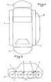
- the vehicle cule according to the invention is further provided under its chassis, at its front and rear parts, as well as on its sides of inflatable elements 10 to 13 serving as floats after inflation.
- the tracks 5 are advantageously removable with a view to transforming the vehicle into non-tracked all-terrain vehicle.
- the additional axles 3 and 4 are intended to ensure the tension of the tracks 5 and to relieve the original axles 1 and 2, and they can be raised in the event of non-use (FIG. 6), for example on firm ground, and their wheels 6 can be removed in this position, so that the vehicle can be used in the usual configuration of motor vehicles, as shown in FIG. 8.
- the track of the vehicle according to the invention can be increased by adding a spacer 14 to the hub 7 of each wheel 6.
- the tracks 5 are advantageously each constituted by a high-strength reinforced plasticized or rubberized canvas provided at regular intervals with crosspieces 15 carrying the attachment of the tracks 5 to the ground, or even propulsion on water, and their internal fixing bar. on the tracks 5 can cooperate in the drive with the tires 9 of the drive wheels 6 '.
- These tires 9 can advantageously be produced in the form of special tire covers, known on the market.
- This drive could also be carried out by means of toothed or notched flanges integral with the wheels 6 ', not shown, having a profile similar to that of the tires 9, and cooperating with said internal bars of the crosspieces 15, which preferably have a section longitudinal trapezoidal.
- the driving wheels 6 ′ can be coupled with the other wheels 6 by means of toothed wheels 16 and chains 17 as well as a clutch 18 provided on the driving axle 1. It it is also possible to ensure this coupling of the wheels by means of belts or gear trains, or by means of angular gear and cardan joints.
- the drive of the other wheels can also be carried out directly by an independent motor for each wheel, or even by connection of the axles by a drive shaft.
- the inflatable elements 10 to 13, shown more particularly in FIGS. 3 and 4, ensure the buoyancy of the vehicle on the water while allowing rolling.
- These elements are generally inflated by means of a pump, a compressor, or even exhaust gases thanks to a suitable capture device, and their deflation is carried out, either simply by means of valves, or by use of '' a Venturi tube cooperating with the exhaust gases to create a suction effect.
- the central element 10 is advantageously constituted by two compartments separated by a longitudinal central wall 21 allowing, by an over-inflation of one of the compartments, the lifting of the associated wheel train and / or the track, so that assembly and disassembly work, as well as troubleshooting are facilitated.
- the vehicle will be steered, in a manner known per se, by braking the drive wheel or wheels on one side, for example by means of control mechanisms by known levers, or by means of a special steering wheel.
- FIG. 6 represents another embodiment of the invention in which only the wheels 6 of the additional axles 3 and 4 are provided with tracks 5 for use on soft ground or as an amphibious vehicle, these axles being able to be raised together with the tracks for use on firm ground as a conventional vehicle.
- the vehicle can be steered by the front axle with possible braking action on one or the other track.
- FIG. 7 shows an embodiment similar to that of FIG. 6, without a track, the wheels 6 of the additional axles 3 and. 4 can be lowered and raised if necessary, and be braked individually for possible assistance to management.
- the wheels 6 can also be arranged under the chassis of the vehicle, so as to raise the latter and obtain a narrow track, as well as to obtain, in in the case of amphibious use, an elevation of the passenger compartment relative to the waterline.
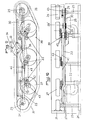
- FIGS 9 and 10 show an alternative embodiment of the invention, in which the additional axles 22 and 25 constitute with two longitudinal members 23 a sub-frame, which can be fixed in a removable manner under the frame 24 (shown in thin dashed lines ).
- the axles 25 On the ends of this subframe are mounted the axles 25, the axes of which are higher than those of the axles 22 and at least one of which is provided with sprockets 26 driven with gear reduction by the corresponding driving wheel 28 of the vehicle by means of a clutch 28 ′ and a set of chain wheels 29 and chains 30, the axis of the idler wheels coinciding with that of the axle of the wheel drive 28, so that the movement of the drive wheel does not change the tension of the chains.
- the drive could also be carried out by means of pulleys and belts, or angular gearboxes with telescopic shaft, or directly by an independent electric, pneumatic or hydraulic motor for each sprocket 26.
- the wheels 27 of the axles 22 are independent suspension, and the axles 22 can be pivoted in use and non-use positions on the subframe by a lockable tilting device known per se.
- the track 31, extending on the wheels 27 and on the sprockets 26, is stretched by said wheels 27, and it has a longitudinal trapezoidal section allowing better penetration into deep snow or on very soft ground, as well as an independent travel of each wheel, allowing the lower strand of the caterpillar to follow the terrain.
- the upper part of the track 31 is supported by longitudinal sliding supports 32. These supports 32 have, between two axles 22, a space allowing the passage of the slack 33 of the track 31 in the raised position of this last (in thin lines in Figure 9).
- the supports 32 are used for fixing the floats.
- the axles 25 are detachably fixed to the subframe, with a tensioning device making it possible to adjust the tension of the transmission chain 30, and of the track 31.
- one or two notches 37 formed in the tracks 31 allow the free orientation of the steering wheels, and these notches can be adjusted in position by means of two marks 38 materialized on the inner face of each track, and which must be matched at the slack take-up, these pins can be combined with attachment means of the element 36, or the like.
- the wheels 27 are driven by means of a clutch 39 and d 'a set of wheels with twin chains 40, one of which is controlled by a set of chains 41 driven by the clutch 39 by the motor shaft, and the other is connected by a chain 42 to a wheel chain 43 secured to the wheel 27, the chains 41 being tensioned by means of tensioners 44, and the travel of the intermediate wheels 27 remaining completely independent (Figure 9).
- the axle 25 of the sprockets 26 forming the drive shaft is advantageously provided with disc or drum brakes 45 which can be actuated separately, from the cockpit, making it possible to direct the vehicle in off-road configuration, and serving as a safety brake in the event of a break in the drive kinematic chain.
- the hubs of the additional wheels 27 and the hubs of the sprockets 26 can be fitted with multiple wheels or wheels with very wide tires to increase the contact surface on the ground, or to increase the buoyancy and propulsion on water.
- the invention it is possible to produce a versatile vehicle which can be used continuously whatever the ground conditions by simple raising or lowering of the additional wheels, and / or inflation or deflation of the inflatable elements, and / or addition or disassembly of different accessory parts.
Landscapes
- Engineering & Computer Science (AREA)
- Mechanical Engineering (AREA)
- Chemical & Material Sciences (AREA)
- Combustion & Propulsion (AREA)
- Transportation (AREA)
- General Engineering & Computer Science (AREA)
- Automatic Cycles, And Cycles In General (AREA)
- Motorcycle And Bicycle Frame (AREA)
Claims (16)
Priority Applications (1)
| Application Number | Priority Date | Filing Date | Title |
|---|---|---|---|
| AT82440005T ATE19608T1 (de) | 1981-02-27 | 1982-02-24 | Gelaende- und amphibienmotorfahrzeug. |
Applications Claiming Priority (4)
| Application Number | Priority Date | Filing Date | Title |
|---|---|---|---|
| FR8104379 | 1981-02-27 | ||
| FR8104379A FR2500793A1 (fr) | 1981-02-27 | 1981-02-27 | Vehicule automobile tout-terrain et amphibie |
| FR8113058 | 1981-06-29 | ||
| FR8113058A FR2508391A2 (fr) | 1981-06-29 | 1981-06-29 | Vehicule automobile tout-terrain et amphibie |
Publications (2)
| Publication Number | Publication Date |
|---|---|
| EP0060209A1 EP0060209A1 (de) | 1982-09-15 |
| EP0060209B1 true EP0060209B1 (de) | 1986-05-07 |
Family
ID=26222258
Family Applications (1)
| Application Number | Title | Priority Date | Filing Date |
|---|---|---|---|
| EP82440005A Expired EP0060209B1 (de) | 1981-02-27 | 1982-02-24 | Gelände- und Amphibienmotorfahrzeug |
Country Status (4)
| Country | Link |
|---|---|
| US (1) | US4459932A (de) |
| EP (1) | EP0060209B1 (de) |
| CA (1) | CA1186949A (de) |
| DE (1) | DE3270944D1 (de) |
Families Citing this family (30)
| Publication number | Priority date | Publication date | Assignee | Title |
|---|---|---|---|---|
| US4671774A (en) * | 1983-01-28 | 1987-06-09 | Owsen Paul J | All terrain vehicle |
| USD305877S (en) | 1987-07-14 | 1990-02-06 | Price Ii Bill | Amphibious vehicle |
| FI875408A7 (fi) * | 1987-12-09 | 1989-06-10 | Groveswing Oy | Axelsystem foer en pao jord eller motsvarande underlag roerlig anordning, i synnerhet foer ett i terraeng anvaendbart fordon. |
| USD331205S (en) | 1990-08-13 | 1992-11-24 | Kenneth Vaughn | All terrain vehicle |
| GB2248428A (en) * | 1990-10-03 | 1992-04-08 | Soo Cheol Jung | Auxiliary endless track mechanism for automobiles |
| GB2254831B (en) * | 1991-04-19 | 1995-01-25 | Alistair Ferguson Buchanan | Amphibious motor cycle |
| US5845593A (en) * | 1995-06-08 | 1998-12-08 | Birkestrand; Orville J. | Man and wind powered aquatic vehicle |
| DE59605246D1 (de) * | 1996-02-16 | 2000-06-21 | Heidenhain Gmbh Dr Johannes | Vorrichtung und Verfahren zur Umschaltung zwischen verschiedenen Betriebsmodi eines Messwertaufnehmers |
| US6435346B1 (en) * | 1996-06-05 | 2002-08-20 | Mark Allain | Inflatable car flood rescue raft |
| US6135220A (en) * | 1998-12-16 | 2000-10-24 | Torvec Inc. | Modular system for track-laying vehicle |
| CA2354229A1 (en) | 2000-07-28 | 2002-01-28 | Donald R. Redman | Amphibious vehicle having an inflatable pontoon |
| US6595812B1 (en) * | 2002-02-15 | 2003-07-22 | Harry Haney | Amphibious vehicle |
| US7040938B2 (en) * | 2002-04-02 | 2006-05-09 | Youn Sang Choi | Armored foldaway inflatable floating device |
| US6866108B2 (en) | 2002-07-17 | 2005-03-15 | United Defense, L.P. | Wheeled-tracked vehicle hybrid |
| US7255184B2 (en) * | 2004-01-02 | 2007-08-14 | Loegering Mfg, Inc. | Track assembly |
| CN1299923C (zh) * | 2004-04-13 | 2007-02-14 | 赵甫全 | 一种水陆两用车 |
| US7329161B2 (en) * | 2004-11-30 | 2008-02-12 | Thomas Roering | Amphibious recreation vehicle |
| RU2291810C1 (ru) * | 2005-07-19 | 2007-01-20 | Государственное образовательное учреждение высшего профессионального образования "Алтайский государственный технический университет им. И.И. Ползунова" (АлтГТУ) | Колесное транспортное средство повышенной проходимости |
| GB2442215B (en) * | 2006-09-29 | 2009-02-18 | Gibbs Tech Ltd | Amphibious vehicle having at least one retractable wheel |
| CA2672466C (en) | 2006-12-12 | 2015-02-03 | Loegering Mfg. Inc. | Conversion system for a wheeled vehicle |
| US20100059297A1 (en) * | 2008-09-10 | 2010-03-11 | Torvec, Inc. | Track suspension |
| GB2457119B (en) * | 2008-09-24 | 2010-09-08 | David Sherman | Manually propelled vehicle with continuous track |
| CA2744681C (en) * | 2010-06-28 | 2018-08-28 | Camoplast Solideal Inc. | All-terrain vehicle (atv) propellable on wheels or endless tracks |
| US9809264B1 (en) * | 2015-07-20 | 2017-11-07 | The United States Of America, As Represented By The Secretary Of The Navy | Track kit for two wheeled balancing ground vehicle |
| CN106515682B (zh) * | 2017-01-04 | 2023-08-04 | 成都四威高科技产业园有限公司 | 一种agv用电动地刹器 |
| CA2995238A1 (en) | 2017-02-15 | 2018-08-15 | Soucy International Inc. | Track assembly and vehicle |
| RU181800U1 (ru) * | 2017-07-19 | 2018-07-26 | Сергей Владимирович Шапошников | Снегоболотоход |
| RU185065U1 (ru) * | 2018-01-24 | 2018-11-19 | Александр Георгиевич Борисов | Снегоболотоход - гусеничный транспортер борисова |
| CN112249242B (zh) * | 2020-12-07 | 2021-03-16 | 烟台智汇港科技创新有限公司 | 一种渔货船甲板平台运输装置 |
| CN113147931B (zh) * | 2021-04-14 | 2023-03-14 | 上海交通大学 | 一种混合模式工作的履带底盘 |
Citations (4)
| Publication number | Priority date | Publication date | Assignee | Title |
|---|---|---|---|---|
| FR1339378A (fr) * | 1961-11-21 | 1963-10-04 | Perfectionnements apportés aux tracteurs ou autres véhicules similaires ayant un train de roues supplémentaires | |
| FR1448586A (fr) * | 1964-09-30 | 1966-08-05 | Chaseside Engineering Company | Véhicule perfectionné |
| FR1525912A (fr) * | 1966-10-17 | 1968-05-24 | Armes De Guerre Fab Nat | Chaîne de propulsion et éléments de chaîne |
| FR2366981A1 (fr) * | 1976-10-08 | 1978-05-05 | Lely Nv C Van Der | Tracteur |
Family Cites Families (23)
| Publication number | Priority date | Publication date | Assignee | Title |
|---|---|---|---|---|
| US1470283A (en) * | 1922-12-05 | 1923-10-09 | John L Opitz | Rear-axle extension device for tractors |
| GB477798A (en) * | 1935-11-23 | 1938-01-06 | Doblhoff Walther | Improvements in or relating to endless-track vehicles with auxiliary wheels |
| US2287290A (en) * | 1939-06-10 | 1942-06-23 | Floyd De L Brown | Mobile unit |
| US2514488A (en) * | 1945-10-26 | 1950-07-11 | James E Hale | Amphibious vehicle |
| DE1045250B (de) * | 1955-01-13 | 1958-11-27 | Fritz Riemerschmid Dr Ing | Raupenfahrwerk fuer Fahrzeuge, insbesondere zum Austausch gegen die Fahrzeugraeder |
| DE1164857B (de) * | 1957-03-22 | 1964-03-05 | Klaus Debus Dipl Ing | Bremseinrichtung fuer Kraftfahrzeuge |
| NL229465A (de) * | 1957-07-16 | |||
| GB864650A (en) * | 1958-09-24 | 1961-04-06 | Hanz Schulz | Device for rendering land vehicles buoyant |
| US2992862A (en) * | 1958-10-31 | 1961-07-18 | Anthony T Fredricks | Endless track for self-propelled snow traversing vehicle |
| FR1480408A (fr) * | 1965-04-05 | 1967-05-12 | Dispositif de roulement au sol | |
| GB1139090A (en) * | 1965-04-05 | 1969-01-08 | Raimo Mikael Kronqvist | Improvements relating to vehicle steering systems |
| US3409100A (en) * | 1966-04-04 | 1968-11-05 | Kronqvist Raimo Mikael | Vehicle with additional lifting wheels for steering |
| GB1133976A (en) * | 1966-05-09 | 1968-11-20 | Martin Robert Dracot Hume | Improvements relating to devices for rendering land vehicles amphibious |
| FR1480953A (fr) * | 1966-05-09 | 1967-05-12 | Dispositif pour rendre amphibies des véhicules terrestres | |
| FR1535105A (fr) * | 1967-08-10 | 1968-08-02 | Lancia Automobili | Véhicule amphibie |
| US3452702A (en) * | 1967-09-05 | 1969-07-01 | Fmc Corp | Vehicle propulsion system |
| CA960728A (en) * | 1974-02-04 | 1975-01-07 | Weinzierl, Frank | Vehicle traction unit |
| US3930553A (en) * | 1974-11-22 | 1976-01-06 | The United States Of America As Represented By The Secretary Of The Army | Track tension control |
| US3958839A (en) * | 1975-02-18 | 1976-05-25 | Foremost International Industries Ltd. | Segmented track |
| US3976153A (en) * | 1975-04-25 | 1976-08-24 | Lateur Michel J | Vehicle with removable traction apparatus |
| DE2617834C3 (de) * | 1976-04-23 | 1979-08-23 | H F M Hohenloher Fahrzeuge- Und Maschinenvertrieb Gmbh, 7183 Langenburg | Straßenfahrzeug |
| JPS5320237A (en) * | 1976-08-08 | 1978-02-24 | Kouji Toyoura | Speciallpurpose vehicle with endless track |
| FR2454949A1 (fr) * | 1979-04-27 | 1980-11-21 | Martin Rene | Ensemble a chenilles adapte pour convertir un vehicule a roues en un vehicule a chenilles |
-
1982
- 1982-02-24 DE DE8282440005T patent/DE3270944D1/de not_active Expired
- 1982-02-24 EP EP82440005A patent/EP0060209B1/de not_active Expired
- 1982-02-26 CA CA000397252A patent/CA1186949A/fr not_active Expired
- 1982-03-01 US US06/353,030 patent/US4459932A/en not_active Expired - Fee Related
Patent Citations (4)
| Publication number | Priority date | Publication date | Assignee | Title |
|---|---|---|---|---|
| FR1339378A (fr) * | 1961-11-21 | 1963-10-04 | Perfectionnements apportés aux tracteurs ou autres véhicules similaires ayant un train de roues supplémentaires | |
| FR1448586A (fr) * | 1964-09-30 | 1966-08-05 | Chaseside Engineering Company | Véhicule perfectionné |
| FR1525912A (fr) * | 1966-10-17 | 1968-05-24 | Armes De Guerre Fab Nat | Chaîne de propulsion et éléments de chaîne |
| FR2366981A1 (fr) * | 1976-10-08 | 1978-05-05 | Lely Nv C Van Der | Tracteur |
Also Published As
| Publication number | Publication date |
|---|---|
| DE3270944D1 (en) | 1986-06-12 |
| US4459932A (en) | 1984-07-17 |
| CA1186949A (fr) | 1985-05-14 |
| EP0060209A1 (de) | 1982-09-15 |
Similar Documents
| Publication | Publication Date | Title |
|---|---|---|
| EP0060209B1 (de) | Gelände- und Amphibienmotorfahrzeug | |
| US6948581B2 (en) | Three-wheel vehicle and concentric intermediate sprocket assembly therefor | |
| US7753155B2 (en) | Front drive system for a snowmobile | |
| US6334496B1 (en) | Crawler device for a crawler type vehicle | |
| US4204583A (en) | Wheeled vehicle with rotatable endless track | |
| US3077238A (en) | Snow vehicle | |
| CA2374657A1 (en) | Atv track conversion | |
| US20200215866A1 (en) | Multi-lifting-tandems suspension | |
| US2187658A (en) | Amphibian vehicle | |
| US3353618A (en) | Articulated vehicle | |
| US2284075A (en) | Snow tractor | |
| US3912031A (en) | Convertible vehicle for all seasons | |
| CA2676937C (en) | Amphibious all terrain vehicle with track assemblies | |
| FR2942426A1 (fr) | Procede et dispositifs permettant le deplacement d'un vehicule sur une surface glissante ou fragile | |
| FR2757106A1 (fr) | Vehicule route-rail pour travaux ferroviaires | |
| US4598783A (en) | Traction device for vehicles | |
| US1885486A (en) | Convertible tractor | |
| FR2752199A1 (fr) | Dispositif permettant d'augmenter la motricite d'un vehicule equipe de pneumatiques | |
| FR2500793A1 (fr) | Vehicule automobile tout-terrain et amphibie | |
| US3595332A (en) | Crawler-type vehicle | |
| FR2508391A2 (fr) | Vehicule automobile tout-terrain et amphibie | |
| US1437408A (en) | Automobile sled | |
| US1659297A (en) | Vehicle-propelling mechanism | |
| FR2529526A1 (fr) | Bateau mu par l'energie disponible sur un vehicule terrestre | |
| US2564377A (en) | Motor sled |
Legal Events
| Date | Code | Title | Description |
|---|---|---|---|
| PUAI | Public reference made under article 153(3) epc to a published international application that has entered the european phase |
Free format text: ORIGINAL CODE: 0009012 |
|
| AK | Designated contracting states |
Designated state(s): AT BE CH DE GB IT LU NL SE |
|
| 17P | Request for examination filed |
Effective date: 19830318 |
|
| GRAA | (expected) grant |
Free format text: ORIGINAL CODE: 0009210 |
|
| AK | Designated contracting states |
Kind code of ref document: B1 Designated state(s): AT BE CH DE GB IT LI LU NL SE |
|
| PG25 | Lapsed in a contracting state [announced via postgrant information from national office to epo] |
Ref country code: NL Effective date: 19860507 Ref country code: IT Free format text: LAPSE BECAUSE OF FAILURE TO SUBMIT A TRANSLATION OF THE DESCRIPTION OR TO PAY THE FEE WITHIN THE PRESCRIBED TIME-LIMIT;WARNING: LAPSES OF ITALIAN PATENTS WITH EFFECTIVE DATE BEFORE 2007 MAY HAVE OCCURRED AT ANY TIME BEFORE 2007. THE CORRECT EFFECTIVE DATE MAY BE DIFFERENT FROM THE ONE RECORDED. Effective date: 19860507 Ref country code: AT Effective date: 19860507 |
|
| REF | Corresponds to: |
Ref document number: 19608 Country of ref document: AT Date of ref document: 19860515 Kind code of ref document: T |
|
| PG25 | Lapsed in a contracting state [announced via postgrant information from national office to epo] |
Ref country code: SE Effective date: 19860531 |
|
| REF | Corresponds to: |
Ref document number: 3270944 Country of ref document: DE Date of ref document: 19860612 |
|
| NLV1 | Nl: lapsed or annulled due to failure to fulfill the requirements of art. 29p and 29m of the patents act | ||
| PG25 | Lapsed in a contracting state [announced via postgrant information from national office to epo] |
Ref country code: LU Free format text: LAPSE BECAUSE OF NON-PAYMENT OF DUE FEES Effective date: 19870228 |
|
| PLBE | No opposition filed within time limit |
Free format text: ORIGINAL CODE: 0009261 |
|
| STAA | Information on the status of an ep patent application or granted ep patent |
Free format text: STATUS: NO OPPOSITION FILED WITHIN TIME LIMIT |
|
| 26N | No opposition filed | ||
| BERE | Be: lapsed |
Owner name: HILDEBRAND GEORGES Effective date: 19870228 |
|
| GBPC | Gb: european patent ceased through non-payment of renewal fee | ||
| PG25 | Lapsed in a contracting state [announced via postgrant information from national office to epo] |
Ref country code: GB Free format text: LAPSE BECAUSE OF NON-PAYMENT OF DUE FEES Effective date: 19881121 |
|
| PG25 | Lapsed in a contracting state [announced via postgrant information from national office to epo] |
Ref country code: LI Effective date: 19890228 Ref country code: CH Effective date: 19890228 Ref country code: BE Effective date: 19890228 |
|
| REG | Reference to a national code |
Ref country code: CH Ref legal event code: PL |
|
| PG25 | Lapsed in a contracting state [announced via postgrant information from national office to epo] |
Ref country code: DE Effective date: 19891101 |