EP0060310A1 - Manchon à garniture - Google Patents
Manchon à garniture Download PDFInfo
- Publication number
- EP0060310A1 EP0060310A1 EP81101851A EP81101851A EP0060310A1 EP 0060310 A1 EP0060310 A1 EP 0060310A1 EP 81101851 A EP81101851 A EP 81101851A EP 81101851 A EP81101851 A EP 81101851A EP 0060310 A1 EP0060310 A1 EP 0060310A1
- Authority
- EP
- European Patent Office
- Prior art keywords
- sleeve
- ribs
- push
- axially
- elastic
- Prior art date
- Legal status (The legal status is an assumption and is not a legal conclusion. Google has not performed a legal analysis and makes no representation as to the accuracy of the status listed.)
- Granted
Links
Images
Classifications
-
- F—MECHANICAL ENGINEERING; LIGHTING; HEATING; WEAPONS; BLASTING
- F16—ENGINEERING ELEMENTS AND UNITS; GENERAL MEASURES FOR PRODUCING AND MAINTAINING EFFECTIVE FUNCTIONING OF MACHINES OR INSTALLATIONS; THERMAL INSULATION IN GENERAL
- F16L—PIPES; JOINTS OR FITTINGS FOR PIPES; SUPPORTS FOR PIPES, CABLES OR PROTECTIVE TUBING; MEANS FOR THERMAL INSULATION IN GENERAL
- F16L17/00—Joints with packing adapted to sealing by fluid pressure
- F16L17/02—Joints with packing adapted to sealing by fluid pressure with sealing rings arranged between outer surface of pipe and inner surface of sleeve or socket
- F16L17/04—Joints with packing adapted to sealing by fluid pressure with sealing rings arranged between outer surface of pipe and inner surface of sleeve or socket with longitudinally split or divided sleeve
-
- F—MECHANICAL ENGINEERING; LIGHTING; HEATING; WEAPONS; BLASTING
- F16—ENGINEERING ELEMENTS AND UNITS; GENERAL MEASURES FOR PRODUCING AND MAINTAINING EFFECTIVE FUNCTIONING OF MACHINES OR INSTALLATIONS; THERMAL INSULATION IN GENERAL
- F16L—PIPES; JOINTS OR FITTINGS FOR PIPES; SUPPORTS FOR PIPES, CABLES OR PROTECTIVE TUBING; MEANS FOR THERMAL INSULATION IN GENERAL
- F16L37/00—Couplings of the quick-acting type
- F16L37/08—Couplings of the quick-acting type in which the connection between abutting or axially overlapping ends is maintained by locking members
- F16L37/084—Couplings of the quick-acting type in which the connection between abutting or axially overlapping ends is maintained by locking members combined with automatic locking
- F16L37/091—Couplings of the quick-acting type in which the connection between abutting or axially overlapping ends is maintained by locking members combined with automatic locking by means of a ring provided with teeth or fingers
Definitions
- the invention relates to a push-in sleeve mentioned in the preamble of claim 1.
- Such a push-in sleeve is known from EP 2 118 A1.
- Similar push-in sleeves, in which the axially extending ribs are not elastically deformable, are known from the publications DE 26 04 099 A1 and DE 27 56 540 A1.
- the axial ribs arranged in the known push-in sleeves serve to center the tip end inserted into the push-in sleeve and to absorb shear loads.
- Such axial ribs are therefore often referred to briefly as “shear load supports”.
- Shear loads are forces acting transversely to the longitudinal axis of the pipe connector, which act in the sense of a parallel displacement of the axes of the spigot end and the sleeve.
- the shear load supports known from the document DE 27 56 540 A1 and from the document DE 26 04 099 A1 are formed from the rigid sleeve and are not elastically deformable.
- the radially inner guide surfaces of the axial ribs are designed to be conical, whereby a centering effect and an absorption of the shear load are brought about, but no contribution is made to absorb buckling forces which are in the sense of The axes of the tip end and the push-in socket bend.
- the axial ribs according to the document DE 26 04 099 A1 with their radially inner edges are essentially axial, but the inside diameter of the sleeve defined by the inner edges of these ribs must be at least slightly larger than the largest possible within the tolerance range Outside diameter of the tip end to be inserted. This requires a relatively large game, especially with diameters of the tip end in the lower tolerance range, so that the contribution of these axial ribs to the improvement of the shear load resistance is only moderate.
- the radial ribs known from EP 2 118 A1 which serve as shear load supports, are, in contrast to the axial ribs discussed above, elastically deformable, but due to their shape from the dimensionally stable sleeve sleeve, they can only be deformed to a limited extent, namely in a resilient manner.
- Such shear load supports are able to compensate for non-rounding of the tip end and deviations of the outer actual diameter of the tip end from nominal values, but only within a relatively narrow tolerance range.
- the invention has for its object to provide an insertion sleeve of the type mentioned, which is able to reliably and effectively support spiked ends against shear load and buckling forces, the outer diameter of which can vary within a large tolerance range due to the manufacturing process.
- the object on which the invention is based is thus achieved in that the axially extending and elastically deformable ribs in the interior of the push-in sleeve, which serve as a shear load support, consist of a full rubber-elastic material which is different from the shaping material of the sleeve.
- This has the effect that the axial ribs can be strongly and very strongly both elastically deformed and pressed, without thereby jeopardizing the rigidity or the dimensional stability or durability of the sleeve.
- the inside diameter defined by the inner edges of such elastically elastic ribs can be made substantially smaller than the smallest outside diameter of the tip end to be inserted in the tolerance range, without the plug sleeve being deformed or damaged when a tip end is inserted with a diameter which is large within the tolerance range. Rather, pipes with diameters both in the region of the smallest and in the region of the largest diameter which is permissible in the tolerance range are held firmly and securely both against axial pull and, in particular, against the effects of transverse forces. This achieves a substantial stabilization of the pipe plug connection produced with the push-in sleeve of the invention.
- the push-in sleeve of the invention is therefore particularly suitable for the production and use in such push-in sleeves which are cylindrical and sleeve-like and are open on both ends and serve to connect two sleeve-free pipe sections or spigot ends.
- the push-in sleeve of the invention with the elastically deformable inner axially extending ribs is used as shear load supports in connection with a resilient support ring which is arranged axially in front of the annular rubber-elastic sealing elements, i.e. towards the sleeve outlet or sleeve collar.
- the inserted tip end is thereby supported on two ring areas, that is, by the elastically deformable ribs and by the resiliently deformable support ring, the rubber-elastic sealing elements being arranged between these two support rings and being subjected to practically no transverse forces other than the sealing forces.
- a plug-in sleeve designed in this way which is open on both sides, in particular has a surprisingly high transverse rigidity, that is to say a high buckling resistance.
- the rubber-elastic sleeve which serves as the inner lining of the push-in sleeve, preferably has projections and / or recesses which complementarily engage in correspondingly arranged projections or recesses on the inside of the sleeve sleeve, so that a connection secured against axial displacement and radial rotation between the sleeve and the Sleeve is obtained.
- Such securing can alternatively or additionally also be effected by or in connection with the spring-elastic support ring on the sleeve collar.
- the sleeve is preferably made of sheet steel.
- the support ring can be made of spring steel or plastic and can be formed in one piece with the sleeve or can be designed as a separate part which is attached to the sleeve and fastened to it by snapping, sticking, press fitting or welding.
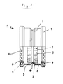
- the push-in sleeve 1 shown in FIG. 1 as an exemplary embodiment of the invention consists of a dimensionally stable sleeve 2 made of corrosion-resistant steel sheet and in this of a rubber-elastic sleeve 3 extending over the entire axial length of the sleeve 2, on which in both collar regions of the push-in sleeve 1 rubber-elastic deformable sealing elements 4 are integrally formed. Seen from the two sleeve collars in the area of the sleeve mirror, i.e. axially centrally in the push-in sleeve 1 shown in FIG.
- axially extending, radially arranged at the same angular distance from one another are elastically deformable ribs 5 formed in one piece from the sleeve 3.
- Both the sleeve 3 and accordingly the ribs 5 consist of a rubber-elastic material, in particular an elastomer with a hardness in the range from 40 to 75 Shore A.
- the axial ribs 5, which serve as a shear load support have a triangular, preferably equilateral, shape in the radial section triangular profile and have on their axially facing the collar collar either either essentially conical shape or are designed with inclined surfaces that form a conical shape overall.
- the end faces of the ribs 5 which are designed in this way and face the collar of the sleeve serve for easier insertion of the tip end onto the radially inner edges 6 of the ribs 5.
- a spring tongue ring 7 made of spring steel is pressed onto the sleeve collar from the outside and has individual bent tongues 8 with which the sleeve 3 is axially fixed in the sleeve 2.
- the axial fixation of the sleeve 3 in the sleeve 2 is further effected by a recess 9 formed in the sleeve 3 and a complementary engagement in this recess 10 which is formed in the sleeve 2.
- the cuff 3 and the sleeve 2 can of course also be formed with a strictly cylindrical outer wall or inner wall and secured in another way, for example by gluing, fixing to the sleeve edge or gluing against relative displacement.
- the spring tongue ring 7 has spring tongues 11 standing radially inward and which serve the additional spring-elastic support of the inserted tip end.
- Such a spigot end inserted into the socket 1 of FIG. 1 is thus supported on two radial surface areas against lateral forces, namely firstly by the elastically deformable ribs 5 and secondly by the resiliently deformable tongues 11 of the resilient spring tongue support ring 7.
- the axial rubber-elastically pressed and deformed ribs 5 alone, but reinforced by the action of the spring-elastic support ring 7 and its spring tongues 11, provide a pipe connector that is largely secured against axial tension. 1 is just held in such a way that it cannot accidentally fall out of the plug connection, even with a vertical detachment, but on the other hand it can also be pulled out of the plug connection again, for example for repair purposes , which then remains usable.
- the spring tongue ring 7 is designed as a separate ring, which is telescopically attached to the collar of the sleeve 2 on this.
- the holding tongues 8 and the spring-elastic supporting spring tongues 11 can of course also be formed in one piece with the sleeve 2.
Landscapes
- Engineering & Computer Science (AREA)
- General Engineering & Computer Science (AREA)
- Mechanical Engineering (AREA)
- Physics & Mathematics (AREA)
- Fluid Mechanics (AREA)
- Joints With Sleeves (AREA)
- Dowels (AREA)
- Magnetically Actuated Valves (AREA)
- Quick-Acting Or Multi-Walled Pipe Joints (AREA)
Priority Applications (4)
| Application Number | Priority Date | Filing Date | Title |
|---|---|---|---|
| AT81101851T ATE14341T1 (de) | 1981-03-12 | 1981-03-12 | Steckmuffe. |
| DE8181101851T DE3171365D1 (en) | 1981-03-12 | 1981-03-12 | Insert sleeve |
| EP81101851A EP0060310B1 (fr) | 1981-03-12 | 1981-03-12 | Manchon à garniture |
| DE19813122846 DE3122846C2 (de) | 1981-03-12 | 1981-06-09 | Muffe |
Applications Claiming Priority (1)
| Application Number | Priority Date | Filing Date | Title |
|---|---|---|---|
| EP81101851A EP0060310B1 (fr) | 1981-03-12 | 1981-03-12 | Manchon à garniture |
Publications (2)
| Publication Number | Publication Date |
|---|---|
| EP0060310A1 true EP0060310A1 (fr) | 1982-09-22 |
| EP0060310B1 EP0060310B1 (fr) | 1985-07-17 |
Family
ID=8187609
Family Applications (1)
| Application Number | Title | Priority Date | Filing Date |
|---|---|---|---|
| EP81101851A Expired EP0060310B1 (fr) | 1981-03-12 | 1981-03-12 | Manchon à garniture |
Country Status (3)
| Country | Link |
|---|---|
| EP (1) | EP0060310B1 (fr) |
| AT (1) | ATE14341T1 (fr) |
| DE (1) | DE3171365D1 (fr) |
Cited By (5)
| Publication number | Priority date | Publication date | Assignee | Title |
|---|---|---|---|---|
| FR2604507A1 (fr) * | 1986-02-18 | 1988-04-01 | Rasmussen Gmbh | Dispositif d'accouplement emboitable pour relier les extremites de deux tubes |
| US5681062A (en) * | 1995-09-27 | 1997-10-28 | Kunimorikagaku Ltd. | Tubular joint |
| EP1087168A1 (fr) * | 1999-09-27 | 2001-03-28 | Legris S.A. | Dispositif de connexion d'une extrémité de conduite à un organe |
| US6231090B1 (en) * | 1999-03-31 | 2001-05-15 | Kunimorikagaku Co. Ltd. | Tubular joint |
| EP2161486A3 (fr) * | 2008-09-08 | 2013-07-31 | Christoph Morach | Manchon tubulaire |
Citations (5)
| Publication number | Priority date | Publication date | Assignee | Title |
|---|---|---|---|---|
| US1926197A (en) * | 1932-09-14 | 1933-09-12 | American Hard Rubber Co | Pipe coupling |
| DE1188879B (de) * | 1960-05-18 | 1965-03-11 | Torfit Werke G A Haseke & Co | Muffenverbindung fuer Rohre aus sproedem Werkstoff |
| BE741333A (fr) * | 1969-11-06 | 1970-04-16 | ||
| LU62127A1 (fr) * | 1969-12-03 | 1971-05-11 | ||
| US3837683A (en) * | 1973-05-09 | 1974-09-24 | Croix Foundry Ltd Soc | Pipe joint sleeve |
Family Cites Families (3)
| Publication number | Priority date | Publication date | Assignee | Title |
|---|---|---|---|---|
| DE2604099C2 (de) * | 1976-02-03 | 1984-04-26 | Schneider Gmbh & Co, 5020 Frechen | Stützring für eine Überschiebedichtung für muffenlose Rohre |
| AT347191B (de) * | 1976-12-24 | 1978-12-11 | Eternit Werke Hatschek L | Rohrkupplung |
| US4126339A (en) * | 1977-11-21 | 1978-11-21 | W. S. Dickey Clay Mfg. Co. | Plain end pipe fitting |
-
1981
- 1981-03-12 AT AT81101851T patent/ATE14341T1/de not_active IP Right Cessation
- 1981-03-12 DE DE8181101851T patent/DE3171365D1/de not_active Expired
- 1981-03-12 EP EP81101851A patent/EP0060310B1/fr not_active Expired
Patent Citations (7)
| Publication number | Priority date | Publication date | Assignee | Title |
|---|---|---|---|---|
| US1926197A (en) * | 1932-09-14 | 1933-09-12 | American Hard Rubber Co | Pipe coupling |
| DE1188879B (de) * | 1960-05-18 | 1965-03-11 | Torfit Werke G A Haseke & Co | Muffenverbindung fuer Rohre aus sproedem Werkstoff |
| BE741333A (fr) * | 1969-11-06 | 1970-04-16 | ||
| LU62127A1 (fr) * | 1969-12-03 | 1971-05-11 | ||
| DE2059311A1 (de) * | 1969-12-03 | 1971-06-09 | Int D Applic De Procedes Ind S | Verbindung zur Kupplung von Rohren |
| US3837683A (en) * | 1973-05-09 | 1974-09-24 | Croix Foundry Ltd Soc | Pipe joint sleeve |
| DE2346344A1 (de) * | 1973-05-09 | 1974-11-21 | Anthes Imperial Ltd | Vorrichtung zur abdichtung zweier rohre |
Cited By (7)
| Publication number | Priority date | Publication date | Assignee | Title |
|---|---|---|---|---|
| FR2604507A1 (fr) * | 1986-02-18 | 1988-04-01 | Rasmussen Gmbh | Dispositif d'accouplement emboitable pour relier les extremites de deux tubes |
| US5681062A (en) * | 1995-09-27 | 1997-10-28 | Kunimorikagaku Ltd. | Tubular joint |
| US6231090B1 (en) * | 1999-03-31 | 2001-05-15 | Kunimorikagaku Co. Ltd. | Tubular joint |
| EP1087168A1 (fr) * | 1999-09-27 | 2001-03-28 | Legris S.A. | Dispositif de connexion d'une extrémité de conduite à un organe |
| AU745944B2 (en) * | 1999-09-27 | 2002-04-11 | Legris S.A. | A device for connecting a pipe end to a member |
| US6517124B1 (en) | 1999-09-27 | 2003-02-11 | Legris S.A. | Device for connecting a pipe end to a member |
| EP2161486A3 (fr) * | 2008-09-08 | 2013-07-31 | Christoph Morach | Manchon tubulaire |
Also Published As
| Publication number | Publication date |
|---|---|
| ATE14341T1 (de) | 1985-08-15 |
| DE3171365D1 (en) | 1985-08-22 |
| EP0060310B1 (fr) | 1985-07-17 |
Similar Documents
| Publication | Publication Date | Title |
|---|---|---|
| EP0913534B1 (fr) | Regard pour des canalisations de fluide et section de regard correspondant | |
| EP0638754B1 (fr) | Joint verrouillé à emboîtement | |
| DE3815167C1 (fr) | ||
| EP0743479B1 (fr) | Arrangement pour la connexion d'un tuyau métallique dans un manchon d'insertion | |
| EP0612947B1 (fr) | Joint verrouillé à emboîtement | |
| DE2304676A1 (de) | Werkstueck, insbesondere dichtungselement, aus elastischem material mit elastischer verstaerkung | |
| DE3336855A1 (de) | Schubgesicherte steckverbindung fuer rohre, insbesondere muffenrohre | |
| EP0159385A1 (fr) | Bague d'étanchéité, manchon avec bague d'étanchéité et son utilisation | |
| DE3710853A1 (de) | Steckverbindung fuer ein rohr oder dergleichen in einem aufnahmeteil | |
| DE29921406U1 (de) | Steckarmatur zum schnellen und lösbaren Anschluß von Druckmittel-Leitungen | |
| DE29610026U1 (de) | Steck-Kupplung | |
| EP0060310B1 (fr) | Manchon à garniture | |
| DE19723594C2 (de) | Rohrverbinder | |
| DE3338899C2 (de) | Dichtring | |
| EP1384923B1 (fr) | Joint d'étanchéité oour un dispositif de rattrapage de jeu axial d'un arbre articulé | |
| WO1982003440A1 (fr) | Raccordement etanche de tubes en matiere plastique resistant aux forces de poussee | |
| DE19717185C2 (de) | Rohrverbindung für Kurzrohre | |
| DE4310795C1 (de) | Steckkupplung | |
| EP0440890A2 (fr) | Connexion de tuyaux souples | |
| DE8107112U1 (de) | Steckmuffe | |
| EP0985867A1 (fr) | Tuyau ondulé en plastique et combinaison de ce tuyau avec un manchon | |
| DE9412445U1 (de) | Unlösbare Rohrverbindung | |
| AT379446B (de) | Steckverbindung | |
| EP0060309B1 (fr) | Manchon à garniture | |
| DE4315958C2 (de) | Rohrverbindung zwischen zwei konzentrisch übereinandergreifenden Rohrelementen |
Legal Events
| Date | Code | Title | Description |
|---|---|---|---|
| PUAI | Public reference made under article 153(3) epc to a published international application that has entered the european phase |
Free format text: ORIGINAL CODE: 0009012 |
|
| AK | Designated contracting states |
Designated state(s): AT BE CH DE FR GB IT NL SE |
|
| 17P | Request for examination filed |
Effective date: 19830322 |
|
| GRAA | (expected) grant |
Free format text: ORIGINAL CODE: 0009210 |
|
| AK | Designated contracting states |
Designated state(s): AT BE CH DE FR GB IT LI NL SE |
|
| PG25 | Lapsed in a contracting state [announced via postgrant information from national office to epo] |
Ref country code: NL Effective date: 19850717 Ref country code: IT Free format text: LAPSE BECAUSE OF FAILURE TO SUBMIT A TRANSLATION OF THE DESCRIPTION OR TO PAY THE FEE WITHIN THE PRESCRIBED TIME-LIMIT;WARNING: LAPSES OF ITALIAN PATENTS WITH EFFECTIVE DATE BEFORE 2007 MAY HAVE OCCURRED AT ANY TIME BEFORE 2007. THE CORRECT EFFECTIVE DATE MAY BE DIFFERENT FROM THE ONE RECORDED. Effective date: 19850717 Ref country code: FR Free format text: THE PATENT HAS BEEN ANNULLED BY A DECISION OF A NATIONAL AUTHORITY Effective date: 19850717 Ref country code: BE Effective date: 19850717 |
|
| REF | Corresponds to: |
Ref document number: 14341 Country of ref document: AT Date of ref document: 19850815 Kind code of ref document: T |
|
| PG25 | Lapsed in a contracting state [announced via postgrant information from national office to epo] |
Ref country code: SE Effective date: 19850730 |
|
| REF | Corresponds to: |
Ref document number: 3171365 Country of ref document: DE Date of ref document: 19850822 |
|
| NLV1 | Nl: lapsed or annulled due to failure to fulfill the requirements of art. 29p and 29m of the patents act | ||
| PG25 | Lapsed in a contracting state [announced via postgrant information from national office to epo] |
Ref country code: AT Effective date: 19860312 |
|
| EN | Fr: translation not filed | ||
| PG25 | Lapsed in a contracting state [announced via postgrant information from national office to epo] |
Ref country code: LI Effective date: 19860331 Ref country code: CH Effective date: 19860331 |
|
| PLBE | No opposition filed within time limit |
Free format text: ORIGINAL CODE: 0009261 |
|
| STAA | Information on the status of an ep patent application or granted ep patent |
Free format text: STATUS: NO OPPOSITION FILED WITHIN TIME LIMIT |
|
| 26N | No opposition filed | ||
| GBPC | Gb: european patent ceased through non-payment of renewal fee | ||
| REG | Reference to a national code |
Ref country code: CH Ref legal event code: PL |
|
| PG25 | Lapsed in a contracting state [announced via postgrant information from national office to epo] |
Ref country code: GB Effective date: 19881121 |
|
| PGFP | Annual fee paid to national office [announced via postgrant information from national office to epo] |
Ref country code: DE Payment date: 19920601 Year of fee payment: 12 |
|
| PG25 | Lapsed in a contracting state [announced via postgrant information from national office to epo] |
Ref country code: DE Effective date: 19931201 |