EP0060351B1 - Dispositif de réception de sacs - Google Patents
Dispositif de réception de sacs Download PDFInfo
- Publication number
- EP0060351B1 EP0060351B1 EP81200275A EP81200275A EP0060351B1 EP 0060351 B1 EP0060351 B1 EP 0060351B1 EP 81200275 A EP81200275 A EP 81200275A EP 81200275 A EP81200275 A EP 81200275A EP 0060351 B1 EP0060351 B1 EP 0060351B1
- Authority
- EP
- European Patent Office
- Prior art keywords
- rod
- bag
- machine
- hook
- bags
- Prior art date
- Legal status (The legal status is an assumption and is not a legal conclusion. Google has not performed a legal analysis and makes no representation as to the accuracy of the status listed.)
- Expired
Links
- 230000005484 gravity Effects 0.000 claims abstract description 11
- 238000004519 manufacturing process Methods 0.000 claims abstract description 8
- 238000004806 packaging method and process Methods 0.000 description 3
- 238000006073 displacement reaction Methods 0.000 description 2
- 239000000463 material Substances 0.000 description 2
- 238000012986 modification Methods 0.000 description 1
- 230000004048 modification Effects 0.000 description 1
- 238000012856 packing Methods 0.000 description 1
Images


Classifications
-
- B—PERFORMING OPERATIONS; TRANSPORTING
- B31—MAKING ARTICLES OF PAPER, CARDBOARD OR MATERIAL WORKED IN A MANNER ANALOGOUS TO PAPER; WORKING PAPER, CARDBOARD OR MATERIAL WORKED IN A MANNER ANALOGOUS TO PAPER
- B31B—MAKING CONTAINERS OF PAPER, CARDBOARD OR MATERIAL WORKED IN A MANNER ANALOGOUS TO PAPER
- B31B70/00—Making flexible containers, e.g. envelopes or bags
- B31B70/74—Auxiliary operations
- B31B70/92—Delivering
- B31B70/94—Delivering singly or in succession
-
- B—PERFORMING OPERATIONS; TRANSPORTING
- B31—MAKING ARTICLES OF PAPER, CARDBOARD OR MATERIAL WORKED IN A MANNER ANALOGOUS TO PAPER; WORKING PAPER, CARDBOARD OR MATERIAL WORKED IN A MANNER ANALOGOUS TO PAPER
- B31B—MAKING CONTAINERS OF PAPER, CARDBOARD OR MATERIAL WORKED IN A MANNER ANALOGOUS TO PAPER
- B31B2160/00—Shape of flexible containers
- B31B2160/10—Shape of flexible containers rectangular and flat, i.e. without structural provision for thickness of contents
-
- B—PERFORMING OPERATIONS; TRANSPORTING
- B31—MAKING ARTICLES OF PAPER, CARDBOARD OR MATERIAL WORKED IN A MANNER ANALOGOUS TO PAPER; WORKING PAPER, CARDBOARD OR MATERIAL WORKED IN A MANNER ANALOGOUS TO PAPER
- B31B—MAKING CONTAINERS OF PAPER, CARDBOARD OR MATERIAL WORKED IN A MANNER ANALOGOUS TO PAPER
- B31B70/00—Making flexible containers, e.g. envelopes or bags
- B31B70/74—Auxiliary operations
- B31B70/92—Delivering
- B31B70/98—Delivering in stacks or bundles
- B31B70/984—Stacking bags on wicket pins
Definitions
- the present invention relates to a bag receiving device intended to be associated with a machine for manufacturing or filling one by one bags, in particular of plastic, each provided along one of their edges parallel to the direction of movement of the bags in the machine, of a hook projecting from the bag and the opening of which is directed towards the receiving device.
- the known receiving devices for the production of hook bags consist of a table on which the bags ejected from the machine are stacked. These devices have the very great disadvantage that the bags, because of the hooks, do not stack properly.
- these bags are essentially intended for the automatic or semi-automatic packaging of products, it is absolutely necessary to manually reconstitute correct batteries in order to package them and transfer them to the various places of use.
- the reconstitution of stacks of bags is very difficult and it is extremely painful and often impossible, for machines. at a high production rate, only one person can, throughout the day, put in the correct stacks bags made by a machine.
- the invention aims to remedy this drawback and to provide a hook bag receiving device, completely different from the receiving devices for bags with gripping holes, such as that which is the subject of French Patent No. 2,021. 676 and which comprises, on the one hand, a vertical stop plate against which the manufactured bags are ejected and, on the other hand, a vertical mandrel located under the gripping holes of the bags which strike the stop plate, which allows to stack automatically and without any manual intervention stacks of perfectly stored bags, regardless of the production rate of the machine.
- This receiving device not only improves the working conditions of the person packing the stacks of bags, but also allows a single person to pack, in good conditions, the production of several machines.
- the bag receiving device can also, when associated with a bag filling machine, remedy said drawbacks and allow the bags to be stacked correctly.
- said receiving device comprises a fixed rod, oriented downwards, which is arranged in the path of the bag expelled at the outlet of the machine and at a distance such from the latter that the rod s 'introduced into the opening of the bag hook when the bag is moving, the section of the rod being smaller than the internal section of the hook so that the hooks threaded on the rod slide along the latter so that the bags' stack by gravity on the rod, means being provided on the rod and arranged to prevent the hooks 4 of the bags from escaping, by gravity, from the lower free end of the rod.
- the distance which separates the outlet of the machine from the zone of the rod cooperating with the hook of the moving bag is less than the distance separating the opening of the hook from the edge of the bag, perpendicular to the direction of movement of the bags in the machine, last leaving the machine so that the bag which has just been produced is still guided in the machine when the rod enters the opening of the hook.
- the above rod is mounted on a support arranged so that the position of the rod is adjustable in two directions, a direction parallel to the direction of movement of the bags in the machine, to allow d '' adapt the position of the rod as a function of the size of the bags taken parallel to the aforementioned direction of movement, and a direction perpendicular to this direction of movement, to allow the rod and the openings of the bag hooks leaving the bag to be aligned machine.
- said receiving device comprises a stop against which the edge of the bag, perpendicular to the said direction of movement and coming out first of the machine, abuts when the bag is ejected from this last, the distance separating the stop from the outlet of the machine being greater than the size of the bag taken parallel to the aforementioned direction of movement.
- the bag receiving device shown in the drawings, is intended to be associated either with a manufacturing machine (FIGS. 1 and 5) or with a filling machine (FIG. 6), one by one, with plastic bags 1 provided , along their edges 2, parallel to the direction of movement of the bags in the machine shown diagrammatically by the arrow 3, of a hook 4 projecting relative to the bag and the opening 5 of which is directed towards the receiving device, the outlet 6 of the machine being sketched in Figures 1, 5 and 6.
- the receiving device shown in Figures 1 to 5, comprises a fixed rod 7 consisting of a first portion 8 substantially vertical, arranged on the path of the hook 4 of the bag 1 expelled from the machine so that this portion 8 of rod is introduced into the opening 5 of the hook of the bag expelled from the machine when the latter is in motion, and a second portion 9 substantially rectilinear, which is connected to portion 8 and which makes an angle 10 sup with it 90 ° angle so that the bags 1 released from the machine and threaded by their hooks 4 on the rod 7, descend along the portion 8 to come to line up and align by gravity on the portion 9 of the rod.
- the above-mentioned angle 10 is chosen so that the bags 1 are stored and stacked on the portion 9 of the rod without escaping from the latter.
- the position of the rod 7 is adjustable relative to the outlet 6 of the machine. To do this, this rod 7 is mounted on a support 19 arranged to allow the rod to be displaced in two directions, a first direction parallel to the aforementioned direction 3, to allow the position of the rod to be adapted as a function of the size of the bags taken parallel to this direction 3, and a second direction, perpendicular to direction 3, to allow the zone 12 of the portion 8 of the rod to be aligned and the openings 5 of the hooks 4 of the bags leaving the machine.
- the support 19 has, to allow the displacement of the aforesaid rod 7 in the above-mentioned first direction, a series of holes 20 aligned in the direction 3 and regularly spaced in which the rod can be inserted and locked in the desired position, to adjust the height of the zone 12 of the rod relative to the path of the hooks 4 of the bags, by a clamping screw 21.
- the support 19 can, to allow the displacement of the rod 7 in the above-mentioned second direction, slide on a bar 22 s' extending parallel to the outlet 6 of the machine, a clamping screw 23 being provided to immobilize, in the selected position, the support 19 on the bar 22.
- the device comprises, as shown in FIG. 5, a stop 24 against which the edge 25 of the bag abuts when the bag is ejected from the machine.
- This stop is advantageously constituted by a rod 26 extending substantially parallel to the portion 8 of the rod 7 and being located at a distance from the outlet 6 of the machine which is greater than the size of the bags taken parallel to the above-mentioned direction 3 .
- This distance is chosen so that the aforementioned edge of the bag comes into contact with the rod 26 after the bag has left the outlet of the machine and it has pivoted around the portion 8 of the rod 7 of a angle less than 90 °.
- the position of the rod 26 is also chosen so that it is, relative to the bag ejected from the machine, further from the edge 2 of the bag with which the hook 4 is associated than from the edge 27 which is parallel to it.
- the rod 26 is of adjustable position and is mounted on a support 28 'arranged, on the bar 22, like the support 19 in order to allow the position of the rod 26 to be adjusted in the two above-mentioned directions in order to adapt the position of said rod, on the one hand, as a function of the size of the bags taken parallel to direction 3 and, on the other hand, as a function of the distance separating the rod 26 from the edge 2 of the bags.
- the axis of the rod 7 can be straight and the section thereof can be constant.
- This rod oriented obliquely downward allows the reception of hooks 4 whose opening 5 is much greater than the diameter of the rod and whose internal section is much greater than that of the rod.
- the latter has means 28 constituted by two members 29 mounted on the rod by means of a spring 30 bringing said members into two extreme positions relative to the stem. A position in which the members 29 protrude with respect to the rod to form a stop for the hooks 4 and an erased position which makes it possible to release said hooks from the end 11 of the rod by sliding them along the axis of the latter .
- the rod 7 ( Figure 6) or the portion 8 of the rod 7 ( Figures 1 and 5) could be located at a distance 16 from the outlet 6 of the machine which is greater than the distance between the opening 5 of the hook 4 of the edge 17 of the bag. That is to say that the bag which has just been manufactured by the machine would be entirely expelled from the machine before the zone 12 of the portion 8 is introduced into the opening 5 of the hook 4 of the bag. This would allow, without adjusting the position of the rod 7, to receive bags whose dimensions, taken parallel to the direction 3, differ.
Landscapes
- Supplying Of Containers To The Packaging Station (AREA)
- Control And Other Processes For Unpacking Of Materials (AREA)
- Sampling And Sample Adjustment (AREA)
- Making Paper Articles (AREA)
- Sheets, Magazines, And Separation Thereof (AREA)
- External Artificial Organs (AREA)
- Packaging Of Special Articles (AREA)
- Stacking Of Articles And Auxiliary Devices (AREA)
- Folding Of Thin Sheet-Like Materials, Special Discharging Devices, And Others (AREA)
- Air Bags (AREA)
- Fertilizing (AREA)
Description
- La présente invention a pour objet un dispositif de réception de sacs destiné à être associé à une machine à fabriquer ou à remplir un à un des sacs, en particulier en matière plastique, pourvus chacun, le long d'un de leurs bords parallèles à la direction de déplacement des sacs dans la machine, d'un crochet faisant saillie par rapport au sac et dont l'ouverture est dirigée vers le dispositif de réception.
- Les dispositifs de réception connus pour la fabrication de sacs à crochet sont constitués par une table sur laquelle s'empilent les sacs éjectés de la machine. Ces dispositifs présentent le très grand inconvénient que les sacs, à cause des crochets, ne s'empilent pas correctement. Comme ces sacs sont essentiellement destinés à l'emballage automatique ou semi-automatique de produits, il est absolument nécessaire de reconstituer manuellement des piles correctes en vue de les emballer et les transférer sur les divers lieux d'utilisation. Vu la consistance de la matière plastique constituant les sacs, le manque d'adhérence de cette matière et l'enchevêtrement fréquent des crochets des sacs, la reconstitution de piles de sacs est très malaisée et il est extrêmement pénible et souvent impossible, pour des machines à cadence de production élevée, qu'une seule personne puisse, à longueur de journée, mettre en piles correctes des sacs fabriqués par une machine.
- L'invention a pour but de remédier à cet inconvénient et de procurer un dispositif de réception de sacs à crochet, totalement différent des dispositifs de réception pour sacs à trous de prise, tels que celui faisant l'objet du brevet français N° 2.021.676 et qui comprend, d'une part, une plaque de butée verticale contre laquelle sont éjectés les sacs fabriqués et, d'autre part, un mandrin vertical se trouvant sous les trous de prise des sacs qui viennent heurter la plaque de butée, qui permet de former automatiquement et sans aucune intervention manuelle des piles de sacs parfaitement rangées et ce, quelle que soit la cadence de production de la machine. Ce dispositif de réception permet non seulement d'améliorer les conditions de travail de la personne emballant les piles de sacs, mais permet également à une seule personne d'emballer, dans de bonnes conditions, la production de plusieurs machines.
- On rencontre pour la manutention et l'emballage de sacs à crochet, dans lesquels des produits ont été emballés, les mêmes inconvénients que pour la manutention et l'emballage des sacs vides. Le dispositif de réception de sacs suivant l'invention peut également, lorsqu'il est associé à une machine de remplissage de sacs, remédier auxdits inconvénients et permettre la mise en pile correcte des sacs.
- A cet effet, suivant l'invention, ledit dispositif de réception comprend une tige fixe, orientée vers le bas, qui est disposée sur le trajet du sac expulsé à la sortie de la machine et à une distance telle de cette dernière que la tige s'introduit dans l'ouverture du crochet du sac lorsque le sac est en mouvement, la section de la tige étant inférieure à la section interne du crochet pour que les crochets enfilés sur la tige glissent le long de cette dernière afin que les sacs s'empilent par gravité sur la tige, des moyens étant prévus sur la tige et agencés pour empêcher les crochets 4 des sacs de s'échapper, par gravité, de l'extrémité libre inférieure de la tige.
- Suivant une forme de réalisation avantageuse de l'invention, la distance qui sépare la sortie de la machine de la zone de la tige coopérant avec le crochet du sac en mouvement est inférieure à la distance séparant l'ouverture du crochet du bord du sac, perpendiculaire à la direction de déplacement des sacs dans la machine, sortant en dernier lieu de la machine afin que le sac qui vient d'être fabriqué soit encore guidé dans la machine lorsque la tige pénètre dans l'ouverture du crochet.
- Suivant un mode de réalisation avantageux de l'invention, la tige susdite est montée sur un support agencé pour que la position de la tige soit réglable suivant deux directions, une direction parallèle à la direction de déplacement des sacs dans la machine, pour permettre d'adapter la position de la tige en fonction de la dimension des sacs prise parallèlement à la direction de déplacement susdite, et une direction perpendiculaire à cette direction de déplacement, pour permettre d'aligner la tige et les ouvertures des crochets des sacs sortant de la machine.
- Suivant une forme de réalisation particulièrement avantageuse de l'invention, ledit dispositif de réception comprend un arrêt contre lequel le bord du sac, perpendiculaire à la direction de déplacement susdite et sortant en premier lieu de la machine, bute lorsque le sac est éjecté de cette dernière, la distance séparant l'arrêt de la sortie de la machine étant supérieure à la dimension du sac prise parallèlement à la direction de déplacement précitée.
- Des exemples non limitatifs ressortiront de la description des dessins.
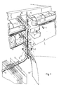
- La figure 1 est une vue en perspective, avec brisures partielles, montrant le dispositif de réception de sacs et la sortie de la machine à fabriquer les sacs à laquelle il est associé.
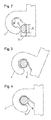
- Les figures 2, 3 et 4 sont des vues en coupe, suivant les lignes II-II, III-III et IV-IV de la figure 1 et à plus grande échelle que celle de la figure 1, montrant la section de la première portion de la tige en trois endroits différents, le crochet d'un sac étant représenté, en traits interrompus, dans la position qu'il occupe lorsqu'il coopère avec la section de tige considérée.
- La figure 5 est une vue analogue à la figure 1 et illustre une variante du dispositif de réception montré à ladite figure 1.
- La figure est une vue en perspective, avec brisures partielles, montrant un dispositif de réception de sacs associé à une machine de remplissage de sacs à crochet.
- Dans les différentes figures, les mêmes chiffres de référence désignent des éléments identiques ou analogues.
- Le dispositif de réception de sacs, représenté aux dessins, est destiné à être associé soit à une machine à fabriquer (figures 1 et 5), soit une machine à remplir (figure 6), un à un, des sacs 1 en matière plastique munis, le long de leurs bords 2, parallèles à la direction de déplacement des sacs dans la machine schématisée par la flèche 3, d'un crochet 4 faisant saillie par rapport au sac et dont l'ouverture 5 est dirigée vers le dispositif de réception, la sortie 6 de la machine étant esquissée aux figures 1, 5 et 6. Le dispositif de réception, montré aux figures 1 à 5, comprend une tige fixe 7 constituée d'une première portion 8 sensiblement verticale, disposée sur le trajet du crochet 4 du sac 1 expulsé de la machine afin que cette portion 8 de tige s'introduise dans l'ouverture 5 du crochet du sac expulsé de la machine quand celui-ci est en mouvement, et une seconde portion 9 sensiblement rectiligne, qui est raccordée à la portion 8 et qui fait avec cette dernière un angle 10 supérieur à 90° afin que les sacs 1 libérés de la machine et enfilés par leurs crochets 4 sur la tige 7, descendent le long de la portion 8 pour venir se ranger et s'aligner par gravité sur la portion 9 de la tige. L'angle 10 susdit est choisi de telle sorte que les sacs 1 se rangent et s'empilent sur la portion 9 de la tige sans s'échapper de cette dernière. Il suffit donc, pour dégager de la tige 7 une pile de sacs parfaitement rangée, de faire glisser les crochets 4 des sacs 1 de la pile sur la portion 9 de tige jusqu'à l'extrémité libre 11 de cette dernière. La zone 12 de la portion 8 de la tige 7, destinée à s'introduire dans le crochet 4 du sac éjecté de la machine dont l'ouverture 5 est de faible dimension, a avantageusement, comme montré à la figure 2, une section sensiblement elliptique dont le petit axe 13, perpendiculaire à la direction de déplacement 3, est inférieur à la dimension 14 de l'ouverture 5 du crochet prise perpendiculairement à la direction 3, le grand axe 15 de l'ellipse étant sensiblement égal au diamètre de la tige 7, ce diamètre étant supérieur à la dimension 14 tandis que la section de la tige 7 est, en dehors de la zone 12, au moins légèrement inférieure à la section interne du crochet 4. La distance 16, qui sépare la sortie 6 de la machine de la zone 12 de la portion 8 de la tige 7, est avantageusement, comme montré à la figure 1, inférieure à la distance qui sépare l'ouverture 5 du crochet 4 du bord 17 du sac, perpendiculaire à la direction 3, sortant en dernier lieu de la machine de manière à ce que le sac qui vient d'être fabriqué soit encore guidé dans la machine quand la zone 12 de la portion 8 de la tige 7 pénètre dans l'ouverture du crochet 4 du sac.
- On constate, au vu des figures 1 à 4, qu'une fois engagé sur la portion 8 de la tige 7 le crochet d'un sac éjecté de la machine ne peut plus se dégager de la tige 7 lorsqu'il coulisse sur cette dernière pour venir se ranger, en position alignée, contre les sacs fabriqués précédemment. En effet, la zone 12, grâce à sa section elliptique, s'engage facilement dans l'ouverture 5 du crochet 4, lorsque le sac sort de la machine, et pénètre dans le crochet pour prendre appui sur la face interne 18 de celui-ci (figure 2). Le sac, toujours guidé dans la machine et propulsé par cette dernière pivote autour de la zone 12 de la tige 7 jusqu'à son éjection. Dès son éjection de la machine, le sac coulisse par gravité sur la portion 8 de la tige 7, comme montré à la figure 3, et son crochet 4 est dans une position telle par rapport à la tige que les dimensions de l'ouverture 5 du crochet et de la tige 7 à l'endroit considéré ne permettent pas un désengagement du crochet par passage de la tige à travers l'ouverture de ce dernier. Par gravité, le sac poursuit son mouvement de descente le long de la portion 8 de la tige et atteint, comme montré la figure 4, une zone où la section de la tige est circulaire, le diamètre de cette zone étant supérieur à la dimension 14 de l'ouverture du crochet. La section de la tige est à l'exception de sa zone 12, de section. circulaire constante. Très rapidement, le sac, suspendu à son crochet, prend une position verticale de sorte que c'est en position verticale que les sacs se rangent et s'alignent sur la portion 9 de la tige 7.
- La position de la tige 7 est réglable par rapport à la sortie 6 de la machine. Pour ce faire, cette tige 7 est montée sur un support 19 agencé pour permettre de déplacer la tige suivant deux directions, une première direction parallèle à la direction 3 précitée, pour permettre d'adapter la position de la tige en fonction de la dimension des sacs prise parallèlement à cette direction 3, et une seconde direction, perpendiculaire à la direction 3, pour permettre d'aligner la zone 12 de la portion 8 de la tige et les ouvertures 5 des crochets 4 des sacs sortant de la machine. Le support 19 présente, pour permettre le déplacement de la tige 7 susdite suivant la première direction susdite, une série de trous 20 alignés suivant la direction 3 et régulièrement espacés dans lesquels la tige peut être introduite et bloquée en position souhaitée, pour régler la hauteur de la zone 12 de la tige par rapport au trajet des crochets 4 des sacs, par une vis de serrage 21. Le support 19 peut, pour permettre le déplacement de la tige 7 suivant la seconde direction susdite, coulisser sur une barre 22 s'étendant parallèlement à la sortie 6 de la machine, une vis de serrage 23 étant prévue pour immobiliser, en position choisie, le support 19 sur la barre 22.
- Il est intéressant, surtout pour des sacs de petites dimensions, de limiter le pivotement des sacs autour de la tige 7, quand celle-ci est introduite dans le crochet et que le sac est éjecté de la machine, afin d'éviter que le sac éjecté prenne une position telle qu'il ne puisse plus, lorsqu'il descend par gravité le long de la portion 8 de la tige, reprendre une position verticale correcte de rangement. Pour ce faire, le dispositif comprend, comme montré à la figure 5, un arrêt 24 contre lequel le bord 25 du sac bute lorsque le sac est éjecté de la machine. Cet arrêt est avantageusement constitué par une tige 26 s'étendant sensiblement parallèlement à la portion 8 de la tige 7 et étant située à une distance de la sortie 6 de la machine qui est supérieure à la dimension des sacs prise parallèlement à la direction 3 susdite. Cette distance est choisie de manière à ce que le bord précité du sac entre en contact avec la tige 26 après que le sac ait quitté la sortie de la machine et qu'il ait pivoté autour de la portion 8 de la tige 7 d'un angle inférieur à 90°. La position de la tige 26 est également choisie pour qu'elle soit, par rapport au sac éjecté de la machine, plus éloignée du bord 2 du sac auquel est associé le crochet 4 que du bord 27 qui lui est parallèle. La tige 26 est de position réglable et est montée sur un support 28' agencé, sur la barre 22, comme le support 19 afin de permettre le réglage de la position de la tige 26 suivant les deux directions précitées afin d'adapter la position de ladite tige, d'une part, en fonction de la dimension des sacs prise parallèlement à la direction 3 et, d'autre part, en fonction de la distance séparant la tige 26 du bord 2 des sacs.
- Comme montré à la figure 6, l'axe de la tige 7 peut être rectiligne et la section de celle-ci peut être constante. Cette tige, orientée obliquement vers le bas permet la réception de crochets 4 dont l'ouverture 5 est largement supérieure au diamètre de la tige et dont la section interne est largement supérieure à celle de la tige. Pour immobiliser les sacs 1 à l'extrémité inférieure libre 11 de la tige, cette dernière présente des moyens 28 constitués par deux organes 29 montés sur la tige par l'intermédiaire d'un ressort 30 amenant lesdits organes dans deux positions extrêmes par rapport à la tige. Une position dans laquelle les organes 29 font saillie par rapport à la tige pour former un arrêt des crochets 4 et une position effacée qui permet de dégager lesdits crochets de l'extrémité 11 de la tige en les faisant coulisser suivant l'axe de cette dernière.
- Il doit être entendu que l'invention n'est nullement limitée aux formes de réalisation décrites et que bien des modifications peuvent être apportées à ces dernières sans sortir du cadre du présent brevet.
- C'est ainsi que la tige 7 (figure 6) ou la portion 8 de la tige 7 (figures 1 et 5) pourrait être située à une distance 16 de la sortie 6 de la machine qui est supérieure à la distance qui sépare l'ouverture 5 du crochet 4 du bord 17 du sac. C'est-à-dire que le sac qui vient d'être fabriqué par la machine serait entièrement expulsé de la machine avant que la zone 12 de la portion 8 s'introduise dans l'ouverture 5 du crochet 4 du sac. Cette façon de faire permettrait, sans réglage de la position de la tige 7, de réceptionner des sacs dont les dimensions, prises parallèlement à la direction 3, diffèrent.
Claims (9)
Priority Applications (12)
| Application Number | Priority Date | Filing Date | Title |
|---|---|---|---|
| DE8181200275T DE3168568D1 (en) | 1981-03-12 | 1981-03-12 | Device for stacking bags |
| AT81200275T ATE11506T1 (de) | 1981-03-12 | 1981-03-12 | Vorrichtung zum sammeln von beuteln. |
| EP81200275A EP0060351B1 (fr) | 1981-03-12 | 1981-03-12 | Dispositif de réception de sacs |
| US06/356,401 US4507038A (en) | 1981-03-12 | 1982-03-09 | Bag-collecting device |
| ZA821544A ZA821544B (en) | 1981-03-12 | 1982-03-09 | Bag-collecting device |
| DK104282A DK151298C (da) | 1981-03-12 | 1982-03-10 | Apparat til opsamling af poser fra en maskine til fremstilling eller fyldning af poserne. |
| AU81271/82A AU551814B2 (en) | 1981-03-12 | 1982-03-10 | Bag-collecting device |
| CA000398083A CA1189102A (fr) | 1981-03-12 | 1982-03-11 | Dispositif d'empilage de sacs |
| PT74565A PT74565B (fr) | 1981-03-12 | 1982-03-11 | Dispositif de reception de sacs |
| NZ199979A NZ199979A (en) | 1981-03-12 | 1982-03-11 | Collecting hooked bags from bag-making machine |
| ES510322A ES510322A0 (es) | 1981-03-12 | 1982-03-11 | "perfeccionamientos en los dispositivos de recepcion de sacos". |
| JP57038220A JPS57210844A (en) | 1981-03-12 | 1982-03-12 | Collector for bag |
Applications Claiming Priority (1)
| Application Number | Priority Date | Filing Date | Title |
|---|---|---|---|
| EP81200275A EP0060351B1 (fr) | 1981-03-12 | 1981-03-12 | Dispositif de réception de sacs |
Publications (2)
| Publication Number | Publication Date |
|---|---|
| EP0060351A1 EP0060351A1 (fr) | 1982-09-22 |
| EP0060351B1 true EP0060351B1 (fr) | 1985-01-30 |
Family
ID=8188115
Family Applications (1)
| Application Number | Title | Priority Date | Filing Date |
|---|---|---|---|
| EP81200275A Expired EP0060351B1 (fr) | 1981-03-12 | 1981-03-12 | Dispositif de réception de sacs |
Country Status (12)
| Country | Link |
|---|---|
| US (1) | US4507038A (fr) |
| EP (1) | EP0060351B1 (fr) |
| JP (1) | JPS57210844A (fr) |
| AT (1) | ATE11506T1 (fr) |
| AU (1) | AU551814B2 (fr) |
| CA (1) | CA1189102A (fr) |
| DE (1) | DE3168568D1 (fr) |
| DK (1) | DK151298C (fr) |
| ES (1) | ES510322A0 (fr) |
| NZ (1) | NZ199979A (fr) |
| PT (1) | PT74565B (fr) |
| ZA (1) | ZA821544B (fr) |
Families Citing this family (8)
| Publication number | Priority date | Publication date | Assignee | Title |
|---|---|---|---|---|
| US6511276B1 (en) * | 2000-06-13 | 2003-01-28 | Tempel Steel Company, Inc. | Parts handling device for press |
| ES2249478T3 (es) * | 2000-10-10 | 2006-04-01 | Wizzoz Pty Ltd | Dispositivo de acoplamiento. |
| US20030019892A1 (en) * | 2001-02-22 | 2003-01-30 | Paul Giampavolo | Apparatus for holding garment hangers |
| USD545068S1 (en) | 2005-03-28 | 2007-06-26 | Paul Giampavolo | Apparel hook with extension |
| USD535111S1 (en) | 2005-04-11 | 2007-01-16 | Paul Giampavolo | Flexible apparel hook |
| US20060249550A1 (en) * | 2005-04-21 | 2006-11-09 | Paul Giampavolo | Flexible apparel hook |
| US20060249549A1 (en) * | 2005-04-21 | 2006-11-09 | Paul Giampavolo | Apparel hook with extension |
| WO2026030785A1 (fr) * | 2024-08-09 | 2026-02-12 | Autorun Technologies Pty Ltd | Système et procédé d'échantillonnage |
Family Cites Families (13)
| Publication number | Priority date | Publication date | Assignee | Title |
|---|---|---|---|---|
| CA49015A (fr) * | 1895-05-22 | Georg Guttenbrumer | Pouvoir d'eau automatique pour tunnels | |
| US1881868A (en) * | 1928-12-10 | 1932-10-11 | Western Electric Co | Magazining device |
| US1968305A (en) * | 1932-02-29 | 1934-07-31 | Andrew Ruen Hanger Co Inc | Discharging mechanism on forming machines |
| US2173077A (en) * | 1938-05-24 | 1939-09-12 | Fedders Mfg Co Inc | Stacking fixture for presses |
| US2589899A (en) * | 1949-06-11 | 1952-03-18 | Vail Mfg Company | Machine for stringing hangers and the like |
| FR1544888A (fr) * | 1967-09-29 | 1968-11-08 | Bemis Co Inc | Appareil et procédé perfectionnés pour fabriquer des sacs, particulièrement des sacs tubulaires en matière plastique |
| DE1805724B1 (de) * | 1968-10-28 | 1970-12-10 | Windmoeller & Hoelscher | Stapel- und Austragvorrichtung fuer Beutelmaschinen zur Herstellung von Traggriffbeuteln |
| US3580378A (en) * | 1968-11-14 | 1971-05-25 | Erik J Pedersen | Automatic hanger discharge |
| US3620354A (en) * | 1970-04-27 | 1971-11-16 | Jerry N Mcmillan | Garment removal apparatus |
| BE788409R (fr) * | 1971-09-08 | 1973-01-02 | Windmoeller & Hoelscher | Dispositif pour former des piles d'objets plats perces de trous, de preference sacs cabas a trous de |
| CA915659A (en) * | 1971-10-29 | 1972-11-28 | B. Lieberman Abraham | Bag dispensing unit and the method of opening and removing the bags therefrom |
| DE2319690A1 (de) * | 1973-04-18 | 1974-11-14 | Siegel Karl Heinz Dr | Verfahren zur herstellung einer aufhaengeverpackung |
| BE843547A (fr) * | 1976-06-29 | 1976-10-18 | Dispositif pour empiler et maintenir en pile des objets plates en particulier des sacs rn matiere plastique |
-
1981
- 1981-03-12 EP EP81200275A patent/EP0060351B1/fr not_active Expired
- 1981-03-12 AT AT81200275T patent/ATE11506T1/de not_active IP Right Cessation
- 1981-03-12 DE DE8181200275T patent/DE3168568D1/de not_active Expired
-
1982
- 1982-03-09 ZA ZA821544A patent/ZA821544B/xx unknown
- 1982-03-09 US US06/356,401 patent/US4507038A/en not_active Expired - Lifetime
- 1982-03-10 AU AU81271/82A patent/AU551814B2/en not_active Ceased
- 1982-03-10 DK DK104282A patent/DK151298C/da active
- 1982-03-11 ES ES510322A patent/ES510322A0/es active Granted
- 1982-03-11 PT PT74565A patent/PT74565B/fr not_active IP Right Cessation
- 1982-03-11 NZ NZ199979A patent/NZ199979A/xx unknown
- 1982-03-11 CA CA000398083A patent/CA1189102A/fr not_active Expired
- 1982-03-12 JP JP57038220A patent/JPS57210844A/ja active Pending
Also Published As
| Publication number | Publication date |
|---|---|
| DK104282A (da) | 1982-09-13 |
| ZA821544B (en) | 1983-01-26 |
| JPS57210844A (en) | 1982-12-24 |
| US4507038A (en) | 1985-03-26 |
| ES8302537A1 (es) | 1983-02-01 |
| AU8127182A (en) | 1982-09-16 |
| AU551814B2 (en) | 1986-05-15 |
| DK151298C (da) | 1988-07-04 |
| CA1189102A (fr) | 1985-06-18 |
| DK151298B (da) | 1987-11-23 |
| ES510322A0 (es) | 1983-02-01 |
| PT74565A (fr) | 1982-04-01 |
| EP0060351A1 (fr) | 1982-09-22 |
| DE3168568D1 (en) | 1985-03-14 |
| PT74565B (fr) | 1983-11-15 |
| ATE11506T1 (de) | 1985-02-15 |
| NZ199979A (en) | 1985-09-13 |
Similar Documents
| Publication | Publication Date | Title |
|---|---|---|
| EP0555709B1 (fr) | Cadre de support momentané d'un élément en plaque horizontal au sein d'une machine | |
| BE1005930A3 (fr) | Necesaire pour boite a casse-croute. | |
| EP0060351A1 (fr) | Dispositif de réception de sacs | |
| FR2600049A1 (fr) | Dispositif de retenue d'un objet a l'entree d'un canal d'empilement. | |
| FR2729376A1 (fr) | Dispositif distributeur de barquettes | |
| CH391577A (fr) | Procédé de transfert de corps creux et dispositif pour sa mise en oeuvre | |
| EP3414198B1 (fr) | Dispositif de saisie de feuilles d'encart, dispositif de chargement, station de reception des poses et machine de traitement d'elements en forme de feuilles | |
| FR2812281A1 (fr) | Dispositif de chargement et/ou de dechargement de support de pile et poste de chargement et/ou dechargement correspondant | |
| EP1486438B1 (fr) | Unité pour l'alimentation d'un poste de travail en conteneurs vides | |
| FR2631924A1 (fr) | Procede automatique de pose de manchon etirable pour l'etiquetage d'emballages plastiques ou metalliques et dispositif de mise en oeuvre de ce procede | |
| EP3994081B1 (fr) | Dispositif de fourniture d'elements de bouchage tries | |
| EP0425323B1 (fr) | Procédé et dispositif pour l'orientation axiale et unidirectionnelle de pièces en forme de douille avec une paroi d'extrémité transversale | |
| EP0252827A1 (fr) | Dispositif de liaison entre une machine de fabrication d'enveloppes et une machine de conditionnement | |
| EP1441584A1 (fr) | Caisse de rangement et/ou de preparation de ligne palangre | |
| FR2492769A1 (fr) | Bidon a embout verseur | |
| EP0647927A1 (fr) | Distributeur automatique d'objets | |
| FR2476597A1 (fr) | Machine d'emballage d'articles de forme spherique et facilement endommageables, notamment des fruits | |
| CH659603A5 (en) | Stacker for laterally feeding bars of material to be machined to a machine tool or a machine-tool feed device | |
| EP0742684A1 (fr) | Dispositif de repiquage rapide de vegetaux | |
| EP4116049B1 (fr) | Trancheuse à pain avec une surface d'appui mobile pour le pain coupé | |
| CH638387A5 (en) | Dispenser for identical products stored in bulk, of parallelepipedal, cubic or spherical shape, and particularly sugar lumps | |
| FR2804654A1 (fr) | Installation d'ensachage comportant plusieurs magasins a sacs | |
| FR2904814A1 (fr) | Procede et dispositif de distribution controlee d'objets indroduits en vrac | |
| FR2588536A1 (fr) | Distributeur de feuilles recues en paquet, notamment dans un copieur automatique. | |
| FR2959217A1 (fr) | Conteneur pour conditionner des sacs et dispositif d'alimentation en sacs d'une ensacheuse utilisant ledit conteneur |
Legal Events
| Date | Code | Title | Description |
|---|---|---|---|
| PUAI | Public reference made under article 153(3) epc to a published international application that has entered the european phase |
Free format text: ORIGINAL CODE: 0009012 |
|
| AK | Designated contracting states |
Designated state(s): AT BE CH DE FR GB IT LU NL SE |
|
| 17P | Request for examination filed |
Effective date: 19821112 |
|
| ITF | It: translation for a ep patent filed | ||
| GRAA | (expected) grant |
Free format text: ORIGINAL CODE: 0009210 |
|
| AK | Designated contracting states |
Designated state(s): AT BE CH DE FR GB IT LI LU NL SE |
|
| REF | Corresponds to: |
Ref document number: 11506 Country of ref document: AT Date of ref document: 19850215 Kind code of ref document: T |
|
| REF | Corresponds to: |
Ref document number: 3168568 Country of ref document: DE Date of ref document: 19850314 |
|
| PG25 | Lapsed in a contracting state [announced via postgrant information from national office to epo] |
Ref country code: LU Free format text: LAPSE BECAUSE OF NON-PAYMENT OF DUE FEES Effective date: 19850331 |
|
| BERE | Be: lapsed |
Owner name: MINIGRIP-BELGIUM Effective date: 19850312 |
|
| PLBE | No opposition filed within time limit |
Free format text: ORIGINAL CODE: 0009261 |
|
| STAA | Information on the status of an ep patent application or granted ep patent |
Free format text: STATUS: NO OPPOSITION FILED WITHIN TIME LIMIT |
|
| BERR | Be: reestablished |
Owner name: *MINIGRIP-BELGIUM Effective date: 19851217 |
|
| 26N | No opposition filed | ||
| ITTA | It: last paid annual fee | ||
| PGFP | Annual fee paid to national office [announced via postgrant information from national office to epo] |
Ref country code: AT Payment date: 19930316 Year of fee payment: 13 |
|
| PGFP | Annual fee paid to national office [announced via postgrant information from national office to epo] |
Ref country code: SE Payment date: 19930322 Year of fee payment: 13 |
|
| PG25 | Lapsed in a contracting state [announced via postgrant information from national office to epo] |
Ref country code: AT Effective date: 19940312 |
|
| PG25 | Lapsed in a contracting state [announced via postgrant information from national office to epo] |
Ref country code: SE Free format text: LAPSE BECAUSE OF NON-PAYMENT OF DUE FEES Effective date: 19940313 |
|
| EUG | Se: european patent has lapsed |
Ref document number: 81200275.6 Effective date: 19941010 |
|
| PGFP | Annual fee paid to national office [announced via postgrant information from national office to epo] |
Ref country code: CH Payment date: 19980220 Year of fee payment: 18 |
|
| PGFP | Annual fee paid to national office [announced via postgrant information from national office to epo] |
Ref country code: GB Payment date: 19980226 Year of fee payment: 18 |
|
| PGFP | Annual fee paid to national office [announced via postgrant information from national office to epo] |
Ref country code: DE Payment date: 19980327 Year of fee payment: 18 |
|
| PGFP | Annual fee paid to national office [announced via postgrant information from national office to epo] |
Ref country code: NL Payment date: 19980330 Year of fee payment: 18 |
|
| PGFP | Annual fee paid to national office [announced via postgrant information from national office to epo] |
Ref country code: BE Payment date: 19990203 Year of fee payment: 19 |
|
| PG25 | Lapsed in a contracting state [announced via postgrant information from national office to epo] |
Ref country code: GB Free format text: LAPSE BECAUSE OF NON-PAYMENT OF DUE FEES Effective date: 19990312 |
|
| PGFP | Annual fee paid to national office [announced via postgrant information from national office to epo] |
Ref country code: FR Payment date: 19990318 Year of fee payment: 19 |
|
| PG25 | Lapsed in a contracting state [announced via postgrant information from national office to epo] |
Ref country code: LI Free format text: LAPSE BECAUSE OF NON-PAYMENT OF DUE FEES Effective date: 19990331 Ref country code: CH Free format text: LAPSE BECAUSE OF NON-PAYMENT OF DUE FEES Effective date: 19990331 |
|
| PG25 | Lapsed in a contracting state [announced via postgrant information from national office to epo] |
Ref country code: NL Free format text: LAPSE BECAUSE OF NON-PAYMENT OF DUE FEES Effective date: 19991001 |
|
| GBPC | Gb: european patent ceased through non-payment of renewal fee |
Effective date: 19990312 |
|
| REG | Reference to a national code |
Ref country code: CH Ref legal event code: PL |
|
| NLV4 | Nl: lapsed or anulled due to non-payment of the annual fee |
Effective date: 19991001 |
|
| PG25 | Lapsed in a contracting state [announced via postgrant information from national office to epo] |
Ref country code: DE Free format text: LAPSE BECAUSE OF NON-PAYMENT OF DUE FEES Effective date: 20000101 |
|
| PG25 | Lapsed in a contracting state [announced via postgrant information from national office to epo] |
Ref country code: BE Free format text: LAPSE BECAUSE OF NON-PAYMENT OF DUE FEES Effective date: 20000331 |
|
| BERE | Be: lapsed |
Owner name: MINIGRIP-BELGIUM Effective date: 20000331 |
|
| PG25 | Lapsed in a contracting state [announced via postgrant information from national office to epo] |
Ref country code: FR Free format text: LAPSE BECAUSE OF NON-PAYMENT OF DUE FEES Effective date: 20001130 |
|
| REG | Reference to a national code |
Ref country code: FR Ref legal event code: ST |