EP0060652A2 - Dispositif de refroidissement pour des machines-outils - Google Patents
Dispositif de refroidissement pour des machines-outils Download PDFInfo
- Publication number
- EP0060652A2 EP0060652A2 EP82301091A EP82301091A EP0060652A2 EP 0060652 A2 EP0060652 A2 EP 0060652A2 EP 82301091 A EP82301091 A EP 82301091A EP 82301091 A EP82301091 A EP 82301091A EP 0060652 A2 EP0060652 A2 EP 0060652A2
- Authority
- EP
- European Patent Office
- Prior art keywords
- tool
- tools
- fixed shaft
- cooling fluid
- hole
- Prior art date
- Legal status (The legal status is an assumption and is not a legal conclusion. Google has not performed a legal analysis and makes no representation as to the accuracy of the status listed.)
- Withdrawn
Links
- 238000001816 cooling Methods 0.000 title claims abstract description 12
- 239000012809 cooling fluid Substances 0.000 claims abstract description 20
- 239000003921 oil Substances 0.000 description 18
- 239000010730 cutting oil Substances 0.000 description 2
- 230000007812 deficiency Effects 0.000 description 2
- 239000000463 material Substances 0.000 description 2
- CWYNVVGOOAEACU-UHFFFAOYSA-N Fe2+ Chemical compound [Fe+2] CWYNVVGOOAEACU-UHFFFAOYSA-N 0.000 description 1
- XAGFODPZIPBFFR-UHFFFAOYSA-N aluminium Chemical compound [Al] XAGFODPZIPBFFR-UHFFFAOYSA-N 0.000 description 1
- 229910052782 aluminium Inorganic materials 0.000 description 1
- 230000006866 deterioration Effects 0.000 description 1
- 239000012530 fluid Substances 0.000 description 1
- 238000010438 heat treatment Methods 0.000 description 1
- 238000003754 machining Methods 0.000 description 1
- 238000003801 milling Methods 0.000 description 1
Images

Classifications
-
- B—PERFORMING OPERATIONS; TRANSPORTING
- B23—MACHINE TOOLS; METAL-WORKING NOT OTHERWISE PROVIDED FOR
- B23Q—DETAILS, COMPONENTS, OR ACCESSORIES FOR MACHINE TOOLS, e.g. ARRANGEMENTS FOR COPYING OR CONTROLLING; MACHINE TOOLS IN GENERAL CHARACTERISED BY THE CONSTRUCTION OF PARTICULAR DETAILS OR COMPONENTS; COMBINATIONS OR ASSOCIATIONS OF METAL-WORKING MACHINES, NOT DIRECTED TO A PARTICULAR RESULT
- B23Q11/00—Accessories fitted to machine tools for keeping tools or parts of the machine in good working condition or for cooling work; Safety devices specially combined with or arranged in, or specially adapted for use in connection with, machine tools
-
- B—PERFORMING OPERATIONS; TRANSPORTING
- B23—MACHINE TOOLS; METAL-WORKING NOT OTHERWISE PROVIDED FOR
- B23Q—DETAILS, COMPONENTS, OR ACCESSORIES FOR MACHINE TOOLS, e.g. ARRANGEMENTS FOR COPYING OR CONTROLLING; MACHINE TOOLS IN GENERAL CHARACTERISED BY THE CONSTRUCTION OF PARTICULAR DETAILS OR COMPONENTS; COMBINATIONS OR ASSOCIATIONS OF METAL-WORKING MACHINES, NOT DIRECTED TO A PARTICULAR RESULT
- B23Q1/00—Members which are comprised in the general build-up of a form of machine, particularly relatively large fixed members
- B23Q1/0009—Energy-transferring means or control lines for movable machine parts; Control panels or boxes; Control parts
- B23Q1/0018—Energy-transferring means or control lines for movable machine parts; Control panels or boxes; Control parts comprising hydraulic means
-
- B—PERFORMING OPERATIONS; TRANSPORTING
- B23—MACHINE TOOLS; METAL-WORKING NOT OTHERWISE PROVIDED FOR
- B23Q—DETAILS, COMPONENTS, OR ACCESSORIES FOR MACHINE TOOLS, e.g. ARRANGEMENTS FOR COPYING OR CONTROLLING; MACHINE TOOLS IN GENERAL CHARACTERISED BY THE CONSTRUCTION OF PARTICULAR DETAILS OR COMPONENTS; COMBINATIONS OR ASSOCIATIONS OF METAL-WORKING MACHINES, NOT DIRECTED TO A PARTICULAR RESULT
- B23Q11/00—Accessories fitted to machine tools for keeping tools or parts of the machine in good working condition or for cooling work; Safety devices specially combined with or arranged in, or specially adapted for use in connection with, machine tools
- B23Q11/10—Arrangements for cooling or lubricating tools or work
- B23Q11/1076—Arrangements for cooling or lubricating tools or work with a cutting liquid nozzle specially adaptable to different kinds of machining operations
-
- B—PERFORMING OPERATIONS; TRANSPORTING
- B23—MACHINE TOOLS; METAL-WORKING NOT OTHERWISE PROVIDED FOR
- B23Q—DETAILS, COMPONENTS, OR ACCESSORIES FOR MACHINE TOOLS, e.g. ARRANGEMENTS FOR COPYING OR CONTROLLING; MACHINE TOOLS IN GENERAL CHARACTERISED BY THE CONSTRUCTION OF PARTICULAR DETAILS OR COMPONENTS; COMBINATIONS OR ASSOCIATIONS OF METAL-WORKING MACHINES, NOT DIRECTED TO A PARTICULAR RESULT
- B23Q9/00—Arrangements for supporting or guiding portable metal-working machines or apparatus
-
- B—PERFORMING OPERATIONS; TRANSPORTING
- B23—MACHINE TOOLS; METAL-WORKING NOT OTHERWISE PROVIDED FOR
- B23Q—DETAILS, COMPONENTS, OR ACCESSORIES FOR MACHINE TOOLS, e.g. ARRANGEMENTS FOR COPYING OR CONTROLLING; MACHINE TOOLS IN GENERAL CHARACTERISED BY THE CONSTRUCTION OF PARTICULAR DETAILS OR COMPONENTS; COMBINATIONS OR ASSOCIATIONS OF METAL-WORKING MACHINES, NOT DIRECTED TO A PARTICULAR RESULT
- B23Q2220/00—Machine tool components
- B23Q2220/002—Tool turrets
-
- Y—GENERAL TAGGING OF NEW TECHNOLOGICAL DEVELOPMENTS; GENERAL TAGGING OF CROSS-SECTIONAL TECHNOLOGIES SPANNING OVER SEVERAL SECTIONS OF THE IPC; TECHNICAL SUBJECTS COVERED BY FORMER USPC CROSS-REFERENCE ART COLLECTIONS [XRACs] AND DIGESTS
- Y10—TECHNICAL SUBJECTS COVERED BY FORMER USPC
- Y10S—TECHNICAL SUBJECTS COVERED BY FORMER USPC CROSS-REFERENCE ART COLLECTIONS [XRACs] AND DIGESTS
- Y10S29/00—Metal working
- Y10S29/054—Fluid control interrelated with machine tool mechanism
-
- Y—GENERAL TAGGING OF NEW TECHNOLOGICAL DEVELOPMENTS; GENERAL TAGGING OF CROSS-SECTIONAL TECHNOLOGIES SPANNING OVER SEVERAL SECTIONS OF THE IPC; TECHNICAL SUBJECTS COVERED BY FORMER USPC CROSS-REFERENCE ART COLLECTIONS [XRACs] AND DIGESTS
- Y10—TECHNICAL SUBJECTS COVERED BY FORMER USPC
- Y10S—TECHNICAL SUBJECTS COVERED BY FORMER USPC CROSS-REFERENCE ART COLLECTIONS [XRACs] AND DIGESTS
- Y10S29/00—Metal working
- Y10S29/087—Multiple fluid paths
-
- Y—GENERAL TAGGING OF NEW TECHNOLOGICAL DEVELOPMENTS; GENERAL TAGGING OF CROSS-SECTIONAL TECHNOLOGIES SPANNING OVER SEVERAL SECTIONS OF THE IPC; TECHNICAL SUBJECTS COVERED BY FORMER USPC CROSS-REFERENCE ART COLLECTIONS [XRACs] AND DIGESTS
- Y10—TECHNICAL SUBJECTS COVERED BY FORMER USPC
- Y10S—TECHNICAL SUBJECTS COVERED BY FORMER USPC CROSS-REFERENCE ART COLLECTIONS [XRACs] AND DIGESTS
- Y10S82/00—Turning
- Y10S82/90—Lathe thermal regulation
-
- Y—GENERAL TAGGING OF NEW TECHNOLOGICAL DEVELOPMENTS; GENERAL TAGGING OF CROSS-SECTIONAL TECHNOLOGIES SPANNING OVER SEVERAL SECTIONS OF THE IPC; TECHNICAL SUBJECTS COVERED BY FORMER USPC CROSS-REFERENCE ART COLLECTIONS [XRACs] AND DIGESTS
- Y10—TECHNICAL SUBJECTS COVERED BY FORMER USPC
- Y10T—TECHNICAL SUBJECTS COVERED BY FORMER US CLASSIFICATION
- Y10T29/00—Metal working
- Y10T29/51—Plural diverse manufacturing apparatus including means for metal shaping or assembling
- Y10T29/5152—Plural diverse manufacturing apparatus including means for metal shaping or assembling with turret mechanism
- Y10T29/5154—Plural diverse manufacturing apparatus including means for metal shaping or assembling with turret mechanism tool turret
-
- Y—GENERAL TAGGING OF NEW TECHNOLOGICAL DEVELOPMENTS; GENERAL TAGGING OF CROSS-SECTIONAL TECHNOLOGIES SPANNING OVER SEVERAL SECTIONS OF THE IPC; TECHNICAL SUBJECTS COVERED BY FORMER USPC CROSS-REFERENCE ART COLLECTIONS [XRACs] AND DIGESTS
- Y10—TECHNICAL SUBJECTS COVERED BY FORMER USPC
- Y10T—TECHNICAL SUBJECTS COVERED BY FORMER US CLASSIFICATION
- Y10T408/00—Cutting by use of rotating axially moving tool
- Y10T408/44—Cutting by use of rotating axially moving tool with means to apply transient, fluent medium to work or product
-
- Y—GENERAL TAGGING OF NEW TECHNOLOGICAL DEVELOPMENTS; GENERAL TAGGING OF CROSS-SECTIONAL TECHNOLOGIES SPANNING OVER SEVERAL SECTIONS OF THE IPC; TECHNICAL SUBJECTS COVERED BY FORMER USPC CROSS-REFERENCE ART COLLECTIONS [XRACs] AND DIGESTS
- Y10—TECHNICAL SUBJECTS COVERED BY FORMER USPC
- Y10T—TECHNICAL SUBJECTS COVERED BY FORMER US CLASSIFICATION
- Y10T409/00—Gear cutting, milling, or planing
- Y10T409/30—Milling
- Y10T409/303976—Milling with means to control temperature or lubricate
- Y10T409/304032—Cutter or work
-
- Y—GENERAL TAGGING OF NEW TECHNOLOGICAL DEVELOPMENTS; GENERAL TAGGING OF CROSS-SECTIONAL TECHNOLOGIES SPANNING OVER SEVERAL SECTIONS OF THE IPC; TECHNICAL SUBJECTS COVERED BY FORMER USPC CROSS-REFERENCE ART COLLECTIONS [XRACs] AND DIGESTS
- Y10—TECHNICAL SUBJECTS COVERED BY FORMER USPC
- Y10T—TECHNICAL SUBJECTS COVERED BY FORMER US CLASSIFICATION
- Y10T82/00—Turning
- Y10T82/25—Lathe
- Y10T82/2527—Lathe having hollow cutter head
Definitions
- the present invention relates to a tool cooling device for machine tools, such as, NC milling machines of the type equipped with an automatic tool changer (hereinafter referred to as machining centers).
- machine tools such as, NC milling machines of the type equipped with an automatic tool changer (hereinafter referred to as machining centers).
- a machining center includes many different types of tools (cutters) accommodated in a tool magazine so that the desired tool is selected and changed automatically to machine a work piece, and a marked tendency to machine non-ferrous material such as aluminum or plastic material is seen lately.
- the machine tool is required to perform cutting at very high speeds with the resulting remarkable increase in the spindle speed and increase in the heating of.tools. Therefore, the conventional practice of supplying a cutting oil to the outside of the tool cannot cool the tool satisfactorily with the resulting considerable deterioration of the tool cutting efficiency.
- a drill is formed with a hole in the lengthwise direction thereof (hereinafter referred to as an oil. hole) so that a cooling fluid such as cutting oil is supplied into the oil hole thus cooling the tool and also forcibly removing the chip with the fluid pressure and thereby reducing the cutting resistance.
- a cooling fluid such as cutting oil
- the usual practice is to force the cooling fluid into the oil hole through a pipe having its one end connected to a cooling fluid pump and other end coupled to the tool holder.
- the tool magazine accommodates tools with oil holes and those having no oil hole as desired and in a suitable manner so that only when the tool having an oil hole is engaged with the spindle, the pipe is connected to the tool holder and the cooling fluid is supplied into the oil hole.
- there is a disadvantage in that it takes a great deal of trouble and much time is required for making the necessary arrangements since the pipe must be connected or disconnected depending on the tool engaged with the spindle.
- a tool cooling device comprising a plurality of cooling fluid distributing units each preliminarily connected to one of the tools with oil holes which are accommodated r in a tool magazine, hereby a selected one of the tools is engaged as such with the spindle and a cooling fluid is supplied automatically only to the tool engaged with the spindle, thereby reducing the time required for making the arrangements necessary for tool changing.
- a tool cooling device for machine tools in which distributing unit means is-provided by means of a fixed shaft having an axial hole communicated with a source of cooling fluid and a plurality of passages arranged at predetermined spaces to be open to the axial hole and to the outer surface of the shaft in the same direction and a plurality of annular members rotatably mounted on the outer surface of the fixed shaft, each having a pipe fitting portion, whereby each of the annular members is connected by a pipe to one of a plurality of tools.to be cooled which are accommodated at suitable spaces within a tool magazine and a cooling fuid is supplied to the tool by way of the axial hole formed through the fixed shaft.
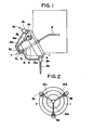
- numeral 1 designates a tool magazine accommodating tool holders 2a, 2b and 2c respectively having tools 3a, 3b and 3c mounted thereon and mounted on a fixed shaft 5 by way of a bearing so as to be rotatable to the left and right about the fixed shaft 5.
- Numeral 6 designates a hole formed through the fixed shaft 5 in the axial direction thereof. In the Figures, those tools having no oil hole are not shown.
- Numeral 4 designates a spindle whereby the tool magazine 1 is rotated so that the desired tool is aligned with the center of the spindle 4 and then engaged therewith or alternatively the tool used previously is disengaged with the spindle 4 and then accommodated back into the tool magazine 1.
- Numeral 3a designates a drill with an oil hole which is engaged with the spindle 4 by way of the tool holder 2a and formed with an oil hole (not shown) extending in the lengthwise direction of its central portion.
- Numeral 7 designates a distributor unit provided at the forward end of the fixed shaft 5 and having a hole communicat- ng with the hole 6 of the fixed shaft 5 whose other end is connected via a pipe 8 to a cooling fluid distributor and a pump (which are not shown).
- the distributor unit 7 includes a plurality (only three are shown) of annular members 7a, 7b and 7c which are respectively connected to pipes 10a, 10b and 10c connected at the other end thereof to the tool holders 2a, 2b and 2c, respectively.
- Fig. 3 shows a principal part of the embodiment of the invention.
- numeral 11 designates a shaft threadedly fitted in the end of the fixed shaft 5 and formed therethrough with a hole 12 communicating with the hole 6 of the fixed shaft 5.
- the hole 12 is formed with passages 13a, 13b and 13c which are arranged at predetermined spaces and open to the outer surface in the same direction.
- the annular members 7a, 7b and 7c are rotatably mounted on the shaft 11 by way of 0-rings 15 and they are provided with pipe fitting portions 14a, 14b and 14c for connection with the pipes 10a, 10b and 10c (see Fig. 1).
- the pipe fitting portions 14b and 14c of the annular members 7b and 7c are not shown.
- Numeral 16 designates a cap provided at the forward end of the shaft 11, and 17 a cock threadedly fitted in the hole 6 and connected from the cooling fluid distributor to the pump by way of the pipe 8.
- the tool holders 2a, 2b and 2c having mounted thereon the oil hole finished tools 3a, 3b and 3c are accommodated at substantially equal spaces in the tool magazine 1.
- the tools are arranged substantially at 120 0 spacing as shown in Fig. 2.
- the annular members 7a, 7b and 7c of the distributor unit 7 are respectively connected to the tool holders 2a, 2b and 2c by the pipes 10a, 10b and 10c (see Figs. 1 and 2).
- the pipe fitting portions 14b and 14c of the annular members 7b and 7c are respectively positioned about 120° apart from the pipe fitting portion 14a of the annular member 7a as shown in (b) and (c) of Fi g. 4 and thus the pipe fitting holes 14b and 14c are closed by the shaft 11.
- the cooling fluid is supplied under pressure from the pump so that the cooling fluid is supplied to the tool holder 2a from the pipe-10a via the pipe 8, the cock 17, the holes 6 and 12 and the passage 13a and the drill 3a is cooled. In this case, the cooling fluid is not supplied to the tool holders 2b and 2c.
- the cooling fluid is supplied in the similar manner and the tool 3b or 3c is cooled.
- the-cooling-fluid is not supplied to the tool since the passages 13a, 13b and 13c formed in the shaft 11 are all closed by the annular members 7a, 7b and 7c.
- the distributor unit is provided with the three annular members
- the present invention is not intended to be limited to it and it is possible to provide one or a number of annular members and arrange the corresponding number of tools with oil holes in the tool magazine so that only a selected one of the passages is communicated with the associated pipe connecting portion at any one time.
- the tools with oil holes are arranged at substantially the equal spaces in the tool magazine, the spacing may be selected as desired so that only a selected one of the passages is connected to the associated pipe connecting portion at any one time.
- the shaft forming a part of the distributor unit is formed with the hole therethrough and the forward end is closed by the cap, the hole may be replaced with a blind hole thereby eliminating the cap.
- the present invention has been described as applied to the cooling of the tools of a machining center, the present invention is not intended to be limited thereto and the invention can be applied for example to any other machine tools such as turret lathes equipped with a plurality of cutting tools.
- the cooling fluid is automatically supplied to the tool without requiring any additional operation with the resulting great decrease in the time required for making arrangements necessary for tool changing. This in turn results in an-improved operating efficiency.
Landscapes
- Engineering & Computer Science (AREA)
- Mechanical Engineering (AREA)
- Auxiliary Devices For Machine Tools (AREA)
Applications Claiming Priority (2)
| Application Number | Priority Date | Filing Date | Title |
|---|---|---|---|
| JP56037479A JPS57156146A (en) | 1981-03-16 | 1981-03-16 | Cooling apparatus for tool of machine tool |
| JP37479/81 | 1981-03-16 |
Publications (2)
| Publication Number | Publication Date |
|---|---|
| EP0060652A2 true EP0060652A2 (fr) | 1982-09-22 |
| EP0060652A3 EP0060652A3 (fr) | 1983-08-10 |
Family
ID=12498647
Family Applications (1)
| Application Number | Title | Priority Date | Filing Date |
|---|---|---|---|
| EP82301091A Withdrawn EP0060652A3 (fr) | 1981-03-16 | 1982-03-03 | Dispositif de refroidissement pour des machines-outils |
Country Status (4)
| Country | Link |
|---|---|
| US (1) | US4442576A (fr) |
| EP (1) | EP0060652A3 (fr) |
| JP (1) | JPS57156146A (fr) |
| KR (1) | KR880002555B1 (fr) |
Cited By (2)
| Publication number | Priority date | Publication date | Assignee | Title |
|---|---|---|---|---|
| EP0154607B1 (fr) * | 1984-03-09 | 1990-08-22 | Büchler B-SET AG | Dispositif pour maintenir une pièce dans une position spatiale |
| GB2259267A (en) * | 1991-09-04 | 1993-03-10 | Blohm Maschinenbau Gmbh | Cooling apparatus for grinding machines |
Families Citing this family (11)
| Publication number | Priority date | Publication date | Assignee | Title |
|---|---|---|---|---|
| US4524655A (en) * | 1983-01-17 | 1985-06-25 | Hardinge Brothers, Inc. | Indexable machine tool turret and attachments therefor |
| JPS6376441U (fr) * | 1987-10-15 | 1988-05-20 | ||
| US5360165A (en) * | 1992-09-28 | 1994-11-01 | Singhal Tara C | Spray paint nozzle and nozzle shroud |
| US5265505A (en) * | 1992-10-29 | 1993-11-30 | Frechette Eugene L | Turret-lathe coolant system |
| US5442953A (en) * | 1993-10-21 | 1995-08-22 | General Electric Company | Dynamic commutator profile system |
| US5564168A (en) * | 1995-04-04 | 1996-10-15 | Caterpillar Inc. | Vertical multi-drill spindle-fluid adapter |
| US6039517A (en) * | 1997-09-30 | 2000-03-21 | Charewicz; Daniel Joseph | Internally cooled magnetic workpiece holder |
| US7762166B2 (en) * | 2007-02-28 | 2010-07-27 | Giannetti Enrico R | Multiple machine tool support block and tool post having internal coolant supply |
| JP6480300B2 (ja) * | 2015-10-16 | 2019-03-06 | 株式会社スギノマシン | ノズル体を装着できる工作機械 |
| ES2886870T3 (es) | 2016-01-18 | 2021-12-21 | Makino Milling Machine | Procedimiento de control para máquina herramienta y máquina herramienta |
| KR20220141488A (ko) * | 2021-04-13 | 2022-10-20 | 주식회사 디엔솔루션즈 | 공작기계의 공구 냉각장치 |
Family Cites Families (6)
| Publication number | Priority date | Publication date | Assignee | Title |
|---|---|---|---|---|
| US2834376A (en) * | 1955-05-10 | 1958-05-13 | Hughes John Farrar | Apparatus for controlling lubricant flow to a plurality of lubricated points |
| US2940473A (en) * | 1955-09-14 | 1960-06-14 | Robert C Smith | Rotary coolant valve |
| US3237872A (en) * | 1965-04-02 | 1966-03-01 | James M Mincy | Lubricant and coolant applicator |
| US3726363A (en) * | 1971-06-08 | 1973-04-10 | Twining E | Coolant spider assembly |
| US4164879A (en) * | 1977-12-14 | 1979-08-21 | The Warner & Swasey Company | Machine tool coolant system |
| JPS56114645A (en) * | 1980-02-08 | 1981-09-09 | Mitsubishi Electric Corp | Cutting oil feed device for nc machining center |
-
1981
- 1981-03-16 JP JP56037479A patent/JPS57156146A/ja active Pending
-
1982
- 1982-03-03 EP EP82301091A patent/EP0060652A3/fr not_active Withdrawn
- 1982-03-06 KR KR8200969A patent/KR880002555B1/ko not_active Expired
- 1982-03-08 US US06/355,454 patent/US4442576A/en not_active Expired - Fee Related
Cited By (3)
| Publication number | Priority date | Publication date | Assignee | Title |
|---|---|---|---|---|
| EP0154607B1 (fr) * | 1984-03-09 | 1990-08-22 | Büchler B-SET AG | Dispositif pour maintenir une pièce dans une position spatiale |
| GB2259267A (en) * | 1991-09-04 | 1993-03-10 | Blohm Maschinenbau Gmbh | Cooling apparatus for grinding machines |
| GB2259267B (en) * | 1991-09-04 | 1995-01-25 | Blohm Maschinenbau Gmbh | Cooling apparatus for grinding machines |
Also Published As
| Publication number | Publication date |
|---|---|
| EP0060652A3 (fr) | 1983-08-10 |
| KR830008791A (ko) | 1983-12-14 |
| JPS57156146A (en) | 1982-09-27 |
| US4442576A (en) | 1984-04-17 |
| KR880002555B1 (ko) | 1988-11-29 |
Similar Documents
| Publication | Publication Date | Title |
|---|---|---|
| EP0060652A2 (fr) | Dispositif de refroidissement pour des machines-outils | |
| US4443929A (en) | Machining center | |
| US4135418A (en) | Clamping device | |
| EP0375783B1 (fr) | Machine-outil | |
| US3791660A (en) | Device for gripping, driving and supplying coolant to a cutting tool having coolant passages therein | |
| EP0527238B1 (fr) | Machine-outil | |
| US5190421A (en) | Coolant supply system for a machine tool | |
| US20110137452A1 (en) | A universal tool mounting system for a machining centre | |
| US4579488A (en) | Boring bar assembly | |
| US6729813B2 (en) | Spindlehead for tools | |
| JPH0627046U (ja) | 工具への流体供給装置 | |
| US3543613A (en) | Rotary cutting tool | |
| US2491635A (en) | Coolant device for tools | |
| EP0463422B1 (fr) | Fixation avec mandrin pour outils de machine à enlèvement de copeaux avec trou interne et outil de machine | |
| US4726717A (en) | Deep-bore drilling machine | |
| EP0072657B1 (fr) | Dispositif additionnel pour le montage sur une broche d'entraînement d'une machine | |
| US5133629A (en) | Tool holding assembly provided with a feeler device | |
| US3221606A (en) | Machine tool spindle cooling system | |
| EP0751843B1 (fr) | Dispositif de refroidissement d'une outil de machine retenue dans une plaque revolver | |
| EP0419428B1 (fr) | Outils de coupe tels que forets, alésoirs, fraises deux tailles et pareils | |
| GB2113579A (en) | Gang head machine tools for machining inclined surfaces | |
| US4327612A (en) | Turret lathe | |
| US5683212A (en) | Clamping assembly for tapered hollow shank of tooling system | |
| US5076123A (en) | Single spindle drive assembly | |
| CA2156334C (fr) | Outil pour l'usinage de precision du metal |
Legal Events
| Date | Code | Title | Description |
|---|---|---|---|
| PUAI | Public reference made under article 153(3) epc to a published international application that has entered the european phase |
Free format text: ORIGINAL CODE: 0009012 |
|
| AK | Designated contracting states |
Designated state(s): BE DE FR GB IT NL SE |
|
| PUAL | Search report despatched |
Free format text: ORIGINAL CODE: 0009013 |
|
| AK | Designated contracting states |
Designated state(s): BE DE FR GB IT NL SE |
|
| 17P | Request for examination filed |
Effective date: 19840107 |
|
| STAA | Information on the status of an ep patent application or granted ep patent |
Free format text: STATUS: THE APPLICATION IS DEEMED TO BE WITHDRAWN |
|
| 18D | Application deemed to be withdrawn |
Effective date: 19850830 |
|
| RIN1 | Information on inventor provided before grant (corrected) |
Inventor name: KITAMURA, KOICHIRO |