EP0060681A1 - Analyseur de gaz combustible - Google Patents
Analyseur de gaz combustible Download PDFInfo
- Publication number
- EP0060681A1 EP0060681A1 EP19820301229 EP82301229A EP0060681A1 EP 0060681 A1 EP0060681 A1 EP 0060681A1 EP 19820301229 EP19820301229 EP 19820301229 EP 82301229 A EP82301229 A EP 82301229A EP 0060681 A1 EP0060681 A1 EP 0060681A1
- Authority
- EP
- European Patent Office
- Prior art keywords
- valve
- gas
- combustible gas
- air
- combustion
- Prior art date
- Legal status (The legal status is an assumption and is not a legal conclusion. Google has not performed a legal analysis and makes no representation as to the accuracy of the status listed.)
- Granted
Links
- 239000007789 gas Substances 0.000 claims abstract description 74
- 238000002485 combustion reaction Methods 0.000 claims abstract description 48
- 239000001301 oxygen Substances 0.000 claims abstract description 20
- 229910052760 oxygen Inorganic materials 0.000 claims abstract description 20
- QVGXLLKOCUKJST-UHFFFAOYSA-N atomic oxygen Chemical compound [O] QVGXLLKOCUKJST-UHFFFAOYSA-N 0.000 claims abstract description 19
- RVTZCBVAJQQJTK-UHFFFAOYSA-N oxygen(2-);zirconium(4+) Chemical compound [O-2].[O-2].[Zr+4] RVTZCBVAJQQJTK-UHFFFAOYSA-N 0.000 claims abstract description 10
- 229910001928 zirconium oxide Inorganic materials 0.000 claims abstract description 9
- 239000000203 mixture Substances 0.000 claims description 10
- 230000000694 effects Effects 0.000 claims description 5
- 238000000034 method Methods 0.000 claims description 4
- 238000001514 detection method Methods 0.000 claims description 3
- 238000012544 monitoring process Methods 0.000 claims description 3
- 230000004044 response Effects 0.000 abstract description 5
- 239000000446 fuel Substances 0.000 description 11
- 238000005259 measurement Methods 0.000 description 11
- 239000002737 fuel gas Substances 0.000 description 8
- 230000005484 gravity Effects 0.000 description 8
- 239000000047 product Substances 0.000 description 5
- 230000001276 controlling effect Effects 0.000 description 4
- 238000010438 heat treatment Methods 0.000 description 4
- 230000001419 dependent effect Effects 0.000 description 3
- 230000000977 initiatory effect Effects 0.000 description 2
- 238000012545 processing Methods 0.000 description 2
- 230000001105 regulatory effect Effects 0.000 description 2
- 230000008859 change Effects 0.000 description 1
- 239000007795 chemical reaction product Substances 0.000 description 1
- 238000012937 correction Methods 0.000 description 1
- 230000002596 correlated effect Effects 0.000 description 1
- 230000000875 corresponding effect Effects 0.000 description 1
- 239000012530 fluid Substances 0.000 description 1
- 239000001307 helium Substances 0.000 description 1
- 229910052734 helium Inorganic materials 0.000 description 1
- SWQJXJOGLNCZEY-UHFFFAOYSA-N helium atom Chemical compound [He] SWQJXJOGLNCZEY-UHFFFAOYSA-N 0.000 description 1
- 238000004519 manufacturing process Methods 0.000 description 1
- 238000012986 modification Methods 0.000 description 1
- 230000004048 modification Effects 0.000 description 1
- 150000002926 oxygen Chemical class 0.000 description 1
- 238000005070 sampling Methods 0.000 description 1
- 239000000126 substance Substances 0.000 description 1
Images

Classifications
-
- G—PHYSICS
- G01—MEASURING; TESTING
- G01N—INVESTIGATING OR ANALYSING MATERIALS BY DETERMINING THEIR CHEMICAL OR PHYSICAL PROPERTIES
- G01N25/00—Investigating or analyzing materials by the use of thermal means
- G01N25/50—Investigating or analyzing materials by the use of thermal means by investigating flash-point; by investigating explosibility
- G01N25/54—Investigating or analyzing materials by the use of thermal means by investigating flash-point; by investigating explosibility by determining explosibility
-
- G—PHYSICS
- G01—MEASURING; TESTING
- G01N—INVESTIGATING OR ANALYSING MATERIALS BY DETERMINING THEIR CHEMICAL OR PHYSICAL PROPERTIES
- G01N31/00—Investigating or analysing non-biological materials by the use of the chemical methods specified in the subgroup; Apparatus specially adapted for such methods
- G01N31/12—Investigating or analysing non-biological materials by the use of the chemical methods specified in the subgroup; Apparatus specially adapted for such methods using combustion
-
- G—PHYSICS
- G01—MEASURING; TESTING
- G01N—INVESTIGATING OR ANALYSING MATERIALS BY DETERMINING THEIR CHEMICAL OR PHYSICAL PROPERTIES
- G01N33/00—Investigating or analysing materials by specific methods not covered by groups G01N1/00 - G01N31/00
- G01N33/0004—Gaseous mixtures, e.g. polluted air
- G01N33/0009—General constructional details of gas analysers, e.g. portable test equipment
- G01N33/0011—Sample conditioning
- G01N33/0013—Sample conditioning by a chemical reaction
Definitions
- the present invention is directed to a combustible gas analyzer and more specifically, to a gas analyzer for determining the heating Wobbe Index of combustible gases.
- An object of the present invention is to provide an improved combustible gas analyzer for determining the Wobbe Index of a combustible gas.
- a combustible gas analyzer comprising means for supplying air and combustible gas at a predetermined flow rate; means for mixing said air and a combustible gas; combustion means for producing a combustion of a mixture of said air and said combustible gas from said mixing means, and a detector for detecting the oxygen content of combustion products from the combustion of said air and said combustible gas by said combustion means, characterized by a valve for controlling the flow of combustible gas to the mixing means, control means responsive to said detector to control said valve to achieve a preselected oxygen content of said-com- bustion products; and a monitor for monitoring the gas flow restricting effect of the valve to enable the detection or indication of the Wobbe Index of said combustible gas.
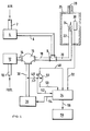
- the gas analyzer is supplied with air and combustible gas through pipelines 2 and 10.
- the pipeline 2 is connected to the input of a first conventional pressure regulator 4 while the output of the pressure regulator 4 is connected to an output pipeline 6.
- the output pipeline 6 is connected to one input of a mixing valve 8.
- the pipeline 6 is arranged to contain a fixed orifice or restriction (not shown) which is the dominating downstream restriction in the flowline supplied by the output of the pressure regulator 4.
- a fixed orifice provides a means for achieving a constant flow rate of the air from the pressure regulator 4 to form a constant flow rate air supply.
- a supply of a combustible gas (not shown) is arranged to supply a fuel gas through the second input pipeline 10 connected to the input of a second conventional pressure regulator 12.
- the output of the second pressure regulator 12 is supplied through an output pipeline 14 to a control valve 16.
- the valve 16 is arranged to provide an orifice which, while variable, is the dominating downstream restriction in the f-lowline supplied by the output of the second pressure regulator 12 . . Since a variation in the flow rate of the fuel gas is desired, a constant flow rate is only achieved for each stable setting of the valve 16 in a similar way to that provided by the orifice in the pipeline 6.
- the output of the control valve 16 is supplied through an output pipeline 18 to a second input of the mixing valve.
- An output of the mixing valve 8 is supplied through pipeline 20 to a burner jet 22 for producing a combustion flame 24.
- the burner jet 22 and the combustion flame 24 are located within a housing 26 providing a combustion chamber for the combustion flame 24. Also located within the housing 26 would be means for initiating the burning of the combustible gas by means of a spark or other device and means for detecting the presence of the flame 24 to provide a control for the flame initiating device. Such devices are well-known in the art and, accordingly, have not been shown in the illustration of the single figure drawing.
- the exhaust gases from the combustion chamber 26 are allowed to escape through a restricted opening 28 in the wall of the combustion chamber 26.
- a well-known zirconium oxide detector 30 is located adjacent to the flame 24 to effect a detection of the oxygen content of the end products of the combustion process to determine a preselected combustion state, e.g., stoichiometric combustion.
- the output of the zirconium oxide detector 30 is applied over an output line 32 to an input of a data processing system 34 which may incorporate a microprocessor.
- the valve 16 is driven by a valve motor 36 connected thereto through a valve stem 38.
- the valve stem 38 is connected to an apparatus for providing an indication of the position of the valve stem 38.
- An example of an apparatus for providing such an indication includes a lever arm 40 attached to the valve stem 38 and arranged to drive the slider 46 of a potentiometer 42 across the resistance element 44 of a potentiometer.
- the resistance element 44 of the potentiometer 42 is connected by electrical lines 48 and 50 to the data processor 34 while the slider 46 is connected by an electrical line 52 to the data processor 34.
- the data processor 34 is arranged to use the input singal from the zirconium oxide detector 30 to produce a control signal on output line 54 for controlling the operation of the valve motor 36.
- the data processor 34 may be used to produce an output signal in response to a signal from the potentiometer 42 on a data output line 56 which is connected to a recorder display 58 for displaying the position of the valve stem 38 as an indication of the Wobbe Index of the fuel gas supplied over the fuel inlet line 10.
- the air supply controlled through the first pressure regulator 4 is supplied to the mixing valve 8 at a constant flow rate in combination with the fuel gas supplied through the second pressure regulator 12 and the control valve 16.
- the combustion of the fuel gas in the presence of the air is effected by the flame 24 in the combustion chamber 26.
- the oxygen content of the combustion products or gases is detected by the zirconium oxide detector 30. Since the control valve 16 functions as a variable orifice, the output signal supplied to the recorder display 58 on output line 56 which is representative of the position of the valve motor 36 is a measurement of the Wobbe Index of the fuel gas. This is the result of having a short orifice which produces an effect dependent on the specific gravity of the fluid flowing therethrough.
- variable orifice produced by the valve 16 is the only significant restriction prior to the burner 22 in the flowline containing the valve 16.
- the calorific value e.g., kj of the gas being burned at the burner 22 will be altered if fuels of different specific gravity are introduced from the fuel line 10.
- the measurement of the movement of the valve stem 38 is dependent on the square root of the specific gravity of the fuel and the calorific content and is, therefore, a direct indication of the Wobbe Index.
- the valve 16 is operated by the data processor 34 by means of the valve motor 36 and valve stem 38 to produce a desired combustion state, e.g., stoichiometric combustion, at the flame 24.
- stoichiometric combustion is only one point on the combustion curve which may be used and only a repeatability is necessary by returning to the same point for each measurement.
- the combustion level is detected by the sensor 30 as a result of the minimal amount of oxygen remaining in the combustion products from the flame 24.
- the representation of the Wobbe Index i.e., valve position, may be displayed on a suitable display or recorded as a record of the Wobbe Index of the fuel gas since the recorder display 58 may include a hard copy recorder as well as a display apparatus, e.g., cathode ray tube (CRT).
- CTR cathode ray tube
- the pressure regulators 4 and 12 are each provided with a feed back line for supplying a pressure feedback signal from T connectors in lines 6 and 18 respectively back to the regulators for controlling the pressure output thereof.
- the analyzer/operator is made independent of specific gravity.
- any change in specific gravity would readjust the pressure equilibrium of the regulator 12 to compensate for a specific gravity whereby the valve stem position is a measure of calorific content. It should be noted that, since the accuracy of the calorific content measurement is dependent on specific gravity of the fuel gas, the proportion of non-combustible gases therein, e.g., helium, will affect the accuracy of the measurement.
- the relationship is an inversely proportional one, i.e., the greater the quantity of non-combustible elements, the lower will be the measurement accuracy.
- the non-combustible content is very small which provide a high measurement accuracy of the calorific content, e.g., 1%.
- the analyzer includes a sample fuel inlet 110 which, with calibration gas inlet 111, is adapted to supply either sample fuel or calibration gas to the system from suitable sources thereof as through an electrically controlled two-position, three- way valve 112 which admits the selected components to the system through pressure regulator 113.
- a flow control valve 114 which may be any suitable type of flow control valve which can be accurately modulated electrically, such as a needle valve is provided to control the sample flow input to the system.
- a metering orifice 115 in conjunction with a sensitive orifice pressure transducer 116 is utilized to accurately measure the sample fuel input to the system.
- Combustion air is applied to the system through an air inlet 117, which may be supplied from a combustion air blower or other source of pressurized air.
- the pressure is regulated by pressure regulator 118 which is backloaded from the common air-gas line 119 as at 120 and a metering orifice 121.
- the sample burner 112 is supplied with the air-gas mixture through line 123 and the products of combustion are sensed as by sensor 124, preferably of Zirconium Oxide (Zr0 2 ).
- the necessary control and data processing functions are performed by electronics shown at 125 and the Wobbe Index output, which may be in the form of a digital register, recorder, direct controller or other means is indicated at 126.
- sensor output is decidedly temperature sensitive in the presence of more than minute amounts of oxygen.
- the temperature of the sensor should also be carefully controlled.
- the output is substantially stable over a wide temperature range, i.e., from about 800°C to 1400°C, and therefore temperature control in the combustion chamber is not critical.
- the relative size of the combustion chamber 22 or 40 is normally sized in accord with the amount of fuel to be burned such that the temperature within the chamber is maintained within the limits where the sensor is not temperature sensitive at or about the stoichiometric point of combustion.
- the Zr0 2 sensor of Figures 1 and 2 can be stabilized with amounts of CaO, MgO or Y 2 0 3 to further stabilize the temperature related response and to enhance the chemical and physical stability of the Zirconium Oxide for use as a sensor. This results in a stable sensor which possesses almost a step-change response at, or about the point of mixture stoichiometry.
- the fuel flow rate can be accurately controlled by the motorized needle valve 114 in conjuction with the orifice115.
- the air is also suitable pressure regulated as seen in that figure.
- the sensorl24 is used in conjunction with the electronics to achieve and maintain substantially stoichiometric proportions for the combustion of the sample gas by controlling the fuel flow.
Landscapes
- Chemical & Material Sciences (AREA)
- Health & Medical Sciences (AREA)
- Life Sciences & Earth Sciences (AREA)
- Biochemistry (AREA)
- General Physics & Mathematics (AREA)
- Pathology (AREA)
- Physics & Mathematics (AREA)
- Analytical Chemistry (AREA)
- Engineering & Computer Science (AREA)
- General Health & Medical Sciences (AREA)
- Immunology (AREA)
- Combustion & Propulsion (AREA)
- Molecular Biology (AREA)
- Chemical Kinetics & Catalysis (AREA)
- Food Science & Technology (AREA)
- Medicinal Chemistry (AREA)
- Investigating Or Analyzing Non-Biological Materials By The Use Of Chemical Means (AREA)
- Investigating Or Analyzing Materials Using Thermal Means (AREA)
- Regulation And Control Of Combustion (AREA)
Applications Claiming Priority (6)
| Application Number | Priority Date | Filing Date | Title |
|---|---|---|---|
| US06/244,538 US4380400A (en) | 1981-03-17 | 1981-03-17 | Combustible gas analyzer |
| US244538 | 1981-03-17 | ||
| US244537 | 1981-03-17 | ||
| US06/244,539 US4359284A (en) | 1981-03-17 | 1981-03-17 | Method and apparatus for determining the Wobbe index of gaseous fuels |
| US244539 | 1981-03-17 | ||
| US06/244,537 US4382698A (en) | 1981-03-17 | 1981-03-17 | Combustible gas analyzer |
Publications (2)
| Publication Number | Publication Date |
|---|---|
| EP0060681A1 true EP0060681A1 (fr) | 1982-09-22 |
| EP0060681B1 EP0060681B1 (fr) | 1987-01-21 |
Family
ID=27399772
Family Applications (1)
| Application Number | Title | Priority Date | Filing Date |
|---|---|---|---|
| EP19820301229 Expired EP0060681B1 (fr) | 1981-03-17 | 1982-03-11 | Analyseur de gaz combustible |
Country Status (2)
| Country | Link |
|---|---|
| EP (1) | EP0060681B1 (fr) |
| DE (1) | DE3275237D1 (fr) |
Cited By (14)
| Publication number | Priority date | Publication date | Assignee | Title |
|---|---|---|---|---|
| EP0086581A1 (fr) * | 1982-02-08 | 1983-08-24 | Honeywell Inc. | Procédé et dispositif d'analyse de gaz |
| DE3408397A1 (de) * | 1984-03-08 | 1985-09-19 | Ruhrgas Ag, 4300 Essen | Verfahren und anordnung zur bestimmung des mischungsverhaeltnisses eines ein sauerstofftraegergas und einen brennstoff enthaltenden gemisches |
| EP0107341A3 (fr) * | 1982-10-06 | 1985-10-02 | Honeywell Inc. | Appareil pour l'analyse d'un gaz combustible |
| FR2564591A1 (fr) * | 1984-05-18 | 1985-11-22 | Siderurgie Fse Inst Rech | Comburimetre et methodes d'utilisation pour la determination du pouvoir comburivore et de l'indice de comburite des combustibles |
| EP0326494A1 (fr) * | 1988-01-29 | 1989-08-02 | Gaz De France (Service National) | Dispositif de mesurage de la puissance calorifique véhiculée par un courant de matière combustible |
| EP0323658A3 (fr) * | 1987-12-05 | 1990-06-13 | N.V. Nederlandse Gasunie | Procédé pour déterminer l'indice wobbe d'un mélange gazeux |
| EP0405693A1 (fr) * | 1989-06-30 | 1991-01-02 | N.V. Nederlandse Gasunie | Appareil et procédé pour la détermination de l'indice de Wobbe |
| EP0438859A3 (en) * | 1990-01-24 | 1993-11-10 | Int Control Automation Finance | Measuring energy in fuel gases |
| US5288149A (en) * | 1992-03-12 | 1994-02-22 | Panametrics, Inc. | Gas calorimeter and wobbe index meter |
| EP2275811A1 (fr) * | 2009-07-13 | 2011-01-19 | ELTRA Entwicklungs- und Vertriebsgesellschaft von elektronischen und physikalischen Geräten mbH | Dispositif de détermination de la composition d'un échantillon, notamment contenant des protéines |
| CN102445465A (zh) * | 2011-09-21 | 2012-05-09 | 周磊 | 一种带有耐压耐腐蚀密封装置的化学品气相危险性检测系统 |
| EP1975511A3 (fr) * | 2007-03-30 | 2014-07-09 | Robert Bosch GmbH | Dispositif de contrôle pour un brûleur à gaz et brûleur à gaz |
| CN106501445A (zh) * | 2016-12-24 | 2017-03-15 | 天津达元吉科技有限公司 | 一种可升降氧指数测试仪 |
| CN111366609A (zh) * | 2020-03-15 | 2020-07-03 | 莱浦顿(上海)工程技术有限公司 | 一种可燃气体分析仪 |
Citations (5)
| Publication number | Priority date | Publication date | Assignee | Title |
|---|---|---|---|---|
| GB1021132A (en) * | 1963-03-06 | 1966-02-23 | Air Liquide | Apparatus for the analysis of gaseous mixtures |
| DE2400246B2 (de) * | 1974-01-04 | 1976-12-02 | Friedrichsfeld Gmbh Steinzeug- Und Kunststoffwerke, 6800 Mannheim | Anordnung zum messen des sauerstoffgehaltes in rauchgaskanaelen |
| US4134289A (en) * | 1977-11-03 | 1979-01-16 | Bailey Meter Company | Gas sampling system having a flow indicator |
| GB1555224A (en) * | 1976-05-03 | 1979-11-07 | Precision Machine Products Inc | Method of and means for accurately measuring the calorific value of combustibile gases |
| EP0008151A1 (fr) * | 1978-08-16 | 1980-02-20 | N.V. Nederlandse Gasunie | Appareil de mesure pour de'terminer une grandeur corrélée avec l'indice de Wobbe d'un gaz ou d'un mélange gazeux ainsi que procédé pour maintenir constant l'indice de Wobbe d'un mélange gazeux |
-
1982
- 1982-03-11 DE DE8282301229T patent/DE3275237D1/de not_active Expired
- 1982-03-11 EP EP19820301229 patent/EP0060681B1/fr not_active Expired
Patent Citations (7)
| Publication number | Priority date | Publication date | Assignee | Title |
|---|---|---|---|---|
| GB1021132A (en) * | 1963-03-06 | 1966-02-23 | Air Liquide | Apparatus for the analysis of gaseous mixtures |
| DE1296838B (de) * | 1963-03-06 | 1969-06-04 | Air Liquide | Gasanalysengeraet |
| DE2400246B2 (de) * | 1974-01-04 | 1976-12-02 | Friedrichsfeld Gmbh Steinzeug- Und Kunststoffwerke, 6800 Mannheim | Anordnung zum messen des sauerstoffgehaltes in rauchgaskanaelen |
| GB1475441A (en) * | 1974-01-04 | 1977-06-01 | Heimke G | Device for sensing the oxygen content of a gaseous stream |
| GB1555224A (en) * | 1976-05-03 | 1979-11-07 | Precision Machine Products Inc | Method of and means for accurately measuring the calorific value of combustibile gases |
| US4134289A (en) * | 1977-11-03 | 1979-01-16 | Bailey Meter Company | Gas sampling system having a flow indicator |
| EP0008151A1 (fr) * | 1978-08-16 | 1980-02-20 | N.V. Nederlandse Gasunie | Appareil de mesure pour de'terminer une grandeur corrélée avec l'indice de Wobbe d'un gaz ou d'un mélange gazeux ainsi que procédé pour maintenir constant l'indice de Wobbe d'un mélange gazeux |
Cited By (17)
| Publication number | Priority date | Publication date | Assignee | Title |
|---|---|---|---|---|
| EP0086581A1 (fr) * | 1982-02-08 | 1983-08-24 | Honeywell Inc. | Procédé et dispositif d'analyse de gaz |
| EP0107341A3 (fr) * | 1982-10-06 | 1985-10-02 | Honeywell Inc. | Appareil pour l'analyse d'un gaz combustible |
| DE3408397A1 (de) * | 1984-03-08 | 1985-09-19 | Ruhrgas Ag, 4300 Essen | Verfahren und anordnung zur bestimmung des mischungsverhaeltnisses eines ein sauerstofftraegergas und einen brennstoff enthaltenden gemisches |
| EP0156200A1 (fr) * | 1984-03-08 | 1985-10-02 | Ruhrgas Aktiengesellschaft | Méthode et dispositif pour déterminer le rapport de mélange d'un mélange contenant un gaz porteur d'oxygène et un carburant |
| FR2564591A1 (fr) * | 1984-05-18 | 1985-11-22 | Siderurgie Fse Inst Rech | Comburimetre et methodes d'utilisation pour la determination du pouvoir comburivore et de l'indice de comburite des combustibles |
| EP0323658A3 (fr) * | 1987-12-05 | 1990-06-13 | N.V. Nederlandse Gasunie | Procédé pour déterminer l'indice wobbe d'un mélange gazeux |
| EP0326494A1 (fr) * | 1988-01-29 | 1989-08-02 | Gaz De France (Service National) | Dispositif de mesurage de la puissance calorifique véhiculée par un courant de matière combustible |
| FR2626673A1 (fr) * | 1988-01-29 | 1989-08-04 | Gaz De France | Procede et dispositif de mesurage de la puissance calorifique vehiculee par un courant de matiere combustible |
| EP0405693A1 (fr) * | 1989-06-30 | 1991-01-02 | N.V. Nederlandse Gasunie | Appareil et procédé pour la détermination de l'indice de Wobbe |
| EP0438859A3 (en) * | 1990-01-24 | 1993-11-10 | Int Control Automation Finance | Measuring energy in fuel gases |
| US5288149A (en) * | 1992-03-12 | 1994-02-22 | Panametrics, Inc. | Gas calorimeter and wobbe index meter |
| EP1975511A3 (fr) * | 2007-03-30 | 2014-07-09 | Robert Bosch GmbH | Dispositif de contrôle pour un brûleur à gaz et brûleur à gaz |
| EP2275811A1 (fr) * | 2009-07-13 | 2011-01-19 | ELTRA Entwicklungs- und Vertriebsgesellschaft von elektronischen und physikalischen Geräten mbH | Dispositif de détermination de la composition d'un échantillon, notamment contenant des protéines |
| CN102445465A (zh) * | 2011-09-21 | 2012-05-09 | 周磊 | 一种带有耐压耐腐蚀密封装置的化学品气相危险性检测系统 |
| CN106501445A (zh) * | 2016-12-24 | 2017-03-15 | 天津达元吉科技有限公司 | 一种可升降氧指数测试仪 |
| CN106501445B (zh) * | 2016-12-24 | 2019-03-05 | 天津达元吉科技有限公司 | 一种可升降氧指数测试仪 |
| CN111366609A (zh) * | 2020-03-15 | 2020-07-03 | 莱浦顿(上海)工程技术有限公司 | 一种可燃气体分析仪 |
Also Published As
| Publication number | Publication date |
|---|---|
| DE3275237D1 (de) | 1987-02-26 |
| EP0060681B1 (fr) | 1987-01-21 |
Similar Documents
| Publication | Publication Date | Title |
|---|---|---|
| CA1168901A (fr) | Methode et dispositif pour determiner l'indice de wobbe d'un carburant gazeux | |
| US4380400A (en) | Combustible gas analyzer | |
| EP0060681B1 (fr) | Analyseur de gaz combustible | |
| US4659306A (en) | Method of and system for determining the ratio between the oxygen-carrying gas content and the fuel content of a mixture | |
| US4125018A (en) | Method of and means for accurately measuring the calorific value of combustible gases | |
| US5288149A (en) | Gas calorimeter and wobbe index meter | |
| US4382698A (en) | Combustible gas analyzer | |
| EP2241810A1 (fr) | Dispositif de commande de débit d'écoulement | |
| US4396299A (en) | Method and apparatus for determining total energy flow in a gas line | |
| CN112578074B (zh) | 具有一氧化碳和甲烷同时测量的燃烧分析仪 | |
| US4351614A (en) | Method of and apparatus for continually monitoring the heating value of a fuel gas using a combustibility meter | |
| NO890291L (no) | Fremgangsmaate og apparat til maaling av varmeverdien i en brennstoffstroem. | |
| CN212622436U (zh) | 具有一氧化碳和甲烷双重测量的燃烧分析仪 | |
| US4511262A (en) | Fuel entrained oxygen compensation for calorific content analyzer | |
| JP3055941B2 (ja) | 可燃ガスの発熱量および天然ガスのウォッベ指数の測定方法および装置 | |
| CA1157354A (fr) | Analyseur de gaz | |
| US6371147B1 (en) | Evaluation and regulation of the thermal power of a flow of combustible gas; characterization of a thermal mass flowmeter | |
| GB2036290A (en) | Fuel sampling system | |
| US5224776A (en) | Instrument and method for heating value measurement by stoichiometric combustion | |
| US4561288A (en) | Flue gas analyzer with carbon monoxide detector | |
| NL7808476A (nl) | Inrichting voor het bepalen van een aan de wobbe-index van een gas of gasmengsel gecorreleerde grootheid, als- mede werkwijze voor het toepassen van deze inrichting. | |
| US3865707A (en) | Combustible mixture analyzer | |
| US4869597A (en) | Calorimeter | |
| GB1584830A (en) | Apparatus and method for measuring the amounts of oxygen and combustibles in a gaseous sample | |
| US4632572A (en) | Impurity compensation for colorific content analyzer |
Legal Events
| Date | Code | Title | Description |
|---|---|---|---|
| PUAI | Public reference made under article 153(3) epc to a published international application that has entered the european phase |
Free format text: ORIGINAL CODE: 0009012 |
|
| AK | Designated contracting states |
Designated state(s): DE FR GB IT NL |
|
| 17P | Request for examination filed |
Effective date: 19820824 |
|
| GRAA | (expected) grant |
Free format text: ORIGINAL CODE: 0009210 |
|
| AK | Designated contracting states |
Kind code of ref document: B1 Designated state(s): DE FR GB IT NL |
|
| ITF | It: translation for a ep patent filed | ||
| REF | Corresponds to: |
Ref document number: 3275237 Country of ref document: DE Date of ref document: 19870226 |
|
| PGFP | Annual fee paid to national office [announced via postgrant information from national office to epo] |
Ref country code: NL Payment date: 19870331 Year of fee payment: 6 |
|
| ET | Fr: translation filed | ||
| PLBE | No opposition filed within time limit |
Free format text: ORIGINAL CODE: 0009261 |
|
| STAA | Information on the status of an ep patent application or granted ep patent |
Free format text: STATUS: NO OPPOSITION FILED WITHIN TIME LIMIT |
|
| 26N | No opposition filed | ||
| PG25 | Lapsed in a contracting state [announced via postgrant information from national office to epo] |
Ref country code: GB Effective date: 19890311 |
|
| PG25 | Lapsed in a contracting state [announced via postgrant information from national office to epo] |
Ref country code: NL Effective date: 19891001 |
|
| GBPC | Gb: european patent ceased through non-payment of renewal fee | ||
| NLV4 | Nl: lapsed or anulled due to non-payment of the annual fee | ||
| PG25 | Lapsed in a contracting state [announced via postgrant information from national office to epo] |
Ref country code: FR Free format text: LAPSE BECAUSE OF NON-PAYMENT OF DUE FEES Effective date: 19891130 |
|
| PG25 | Lapsed in a contracting state [announced via postgrant information from national office to epo] |
Ref country code: DE Effective date: 19891201 |
|
| REG | Reference to a national code |
Ref country code: FR Ref legal event code: ST |