EP0060689A1 - Koordinaten-Messsysteme - Google Patents
Koordinaten-Messsysteme Download PDFInfo
- Publication number
- EP0060689A1 EP0060689A1 EP82301248A EP82301248A EP0060689A1 EP 0060689 A1 EP0060689 A1 EP 0060689A1 EP 82301248 A EP82301248 A EP 82301248A EP 82301248 A EP82301248 A EP 82301248A EP 0060689 A1 EP0060689 A1 EP 0060689A1
- Authority
- EP
- European Patent Office
- Prior art keywords
- probe
- measured
- ordinate
- data
- measuring
- Prior art date
- Legal status (The legal status is an assumption and is not a legal conclusion. Google has not performed a legal analysis and makes no representation as to the accuracy of the status listed.)
- Granted
Links
Images
Classifications
-
- G—PHYSICS
- G01—MEASURING; TESTING
- G01B—MEASURING LENGTH, THICKNESS OR SIMILAR LINEAR DIMENSIONS; MEASURING ANGLES; MEASURING AREAS; MEASURING IRREGULARITIES OF SURFACES OR CONTOURS
- G01B7/00—Measuring arrangements characterised by the use of electric or magnetic techniques
-
- G—PHYSICS
- G01—MEASURING; TESTING
- G01B—MEASURING LENGTH, THICKNESS OR SIMILAR LINEAR DIMENSIONS; MEASURING ANGLES; MEASURING AREAS; MEASURING IRREGULARITIES OF SURFACES OR CONTOURS
- G01B7/00—Measuring arrangements characterised by the use of electric or magnetic techniques
- G01B7/004—Measuring arrangements characterised by the use of electric or magnetic techniques for measuring coordinates of points
- G01B7/008—Measuring arrangements characterised by the use of electric or magnetic techniques for measuring coordinates of points using coordinate measuring machines
- G01B7/012—Contact-making feeler heads therefor
Definitions
- the present invention relates to co-ordinate measuring systems for determining the relative dimensions of an object.
- a co-ordinate measuring system for determining the relative dimensions of an object, the system being characterised by measuring means for measuring the relative dimensions of surfaces defining the object, display means for displaying the relative dimensions determined by the measuring means, actuation of the measuring means causing the display means to display the relative dimensions at the instant contact is made by the measuring means with the surface being measured, and comparing means for comparing the relative dimensions displayed on the display means with the relative location of the measuring means, the comparing means being operative to cause the display means to be reset when the difference between said relative dimensions and said relative location exceeds a predetermined value.
- a preferred embodiment of the present invention described hereinbelow is intended at least partially to solve the aforementioned problems associated with the prior art by utilising the principle of instantaneous electrical contact closure when a probe surface contacts a surface of the part to be measured.
- the probe is one contact of a switch and the other switch contact is the part being measured. This is accomplished by providing a probe which typically comprises four insulated faces wherein opposite faces are interconnected so as to form two parallel "X" co-ordinate probe contact surfaces and two parallel "Y" co-ordinate probe contact surfaces.
- the part to be measured is electrically connected to ground potential.
- the system can be manually reset unlatching the data exhibited on the visual display devices. Alternatively, the data can be automatically recorded and subsequently unlatched.
- the relative position of displacement heads on the co-ordinate measuring system or machine is compared with the data shown on the visual display devices and, if the difference therebetween exceeds a predetermined amount, the data displayed is automatically unlatched and the system is reset.
- the co-ordinate measuring system or machine constituting the preferred embodiment of the invention can make accurate, repeatable measurements, the measurement of a part occuring at the instant a probe touches the surface thereof. Deflection of the probe and/or the part being measured does not affect the measurements being taken.
- the measurements taken by the probe are automatically recorded, and the data displayed and/or recorded is automatically unlatched after the probe has been moved a predetermined distance away from the surface of the part being measured.
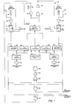
- FIG. 1 is a schematic diagram of a circuit 10 used by a co-ordinate measuring system embodying the present invention.
- the circuit 10 utilizes a "touch" probe which typically comprises four insulated faces, having opposite faces interconnected so as to form two "X" co-ordinate probe contact surfaces 12 and two "Y" co-ordinate probe contact surfaces 14.
- Contact of the probe surfaces 12, 14 with a clean conductive surface causes a change of state in flip-flop devices 16, 18 respectively which, in turn, control latch display devices 20, 22 respectively.
- the operation of the display devices 20, 22 and the entire system can, in turn, be controlled by a microcomputer 24.
- Each of the two probe surfaces 12, i.e., the probe surfaces for the "X" co-ordinate axis, is connected to a positive voltage source 30 through a resistance 32.
- the voltage source 30 provides a low voltage, e.g. 5 volts.
- the probe surfaces 12 are also connected to the input of an inverting amplifier 34 whose output is connected to the clock or trigger terminal (CLK) of the flip-flop 16.
- CLK clock or trigger terminal
- each of the two probe surfaces 14, i.e., the probe surfaces for the "Y" co-ordinate axis, is connected to the positive voltage source 30 through a resistance 36 and is connected to the input to an inverting amplifier 38 whose output is connected to the clock or trigger terminal of the flip-flop 18.
- the Q output of the flip-flop 18 is connected to the latch display device 22 which, when actuated, "freezes” and displays the measurement taken by the probe along with the "Y" axis.
- the Q outputs of both flip-flops 16, 18 are also connected to the inputs of an exclusive “OR” gate 40 and to "AND” gates 42, 44.
- the output of "OR” gate 40 is connected to the input of an amplifier 46 whose output is, in turn, connected to the input of a buzzer 48, the operation of which will be hereinafter described.
- the output of "AND” gate 42 is connected to external recording devices (not shown) which are used for recording the data shown on the latch display devices 20, 22.
- the recording devices are provided with means for signalling when the data has been recorded. These signalling means are connected to an input of the "AND” gate 44 along with the Q outputs of the flip-flops 16, 18.
- the output of the "AND” gate 44 is, in turn, connected to the microcomputer 24.
- the microcomputer 24 is connected to a plurality of input/output expanders 50 which are connected to the latch display devices 20, 22 and to co-ordinate measuring machine (CMM) displays 52, 54 which display the relative position of "X" and "Y" displacement heads, 56, 58 respectively.
- CCM co-ordinate measuring machine
- a thumbwheel switch 60 is also provided and connected to the input/output expanders 50 and is used to adjust the sensitivity of the system, as will be hereinafter described.
- the system can be manually reset by the operator by pressing a reset button 62 or it can be reset automatically by the microcomputer 24.
- One side of the reset button 62 is connected to ground while the other side is connected to the input of an inverting amplifier 64 whose output is connected to one of the inputs of an "OR" gate 66, the other input of which is connected to the output of the microcomputer 24.
- the output of the gate 66 is, in turn, connected to the input of an inverting amplifier 68 whose output is connected to clear ( CLR ) terminals on both of the flip-flops 16, 18.
- the part being measured is electrically connected to ground potential. If the probe is being operated manually, it is allowed to touch both the "X" and the "Y” surfaces of the part. While this is occurring, the "X" and “Y” displacement heads cause the actual position in space of the probe to be shown on the CMM displays 52, 54 and on the latches/display devices 20, 22 respectively. At the instant the probe touches either the "X” or "Y” axis of the part, an electrical circuit is made through either probe surfaces 12 or 14 to ground potential, via the part being measured. This change in voltage potential causes inverting amplifier 34 or 38 to apply a positive voltage to either flip-flop 16 or 18 and trigger same.
- Flip-flop 16 would be actuated for a measurement in the "X” direction whereas flip-flop 18 would be actuated for a measurement in the "Y” direction.
- flip-flop 16 When flip-flop 16 is triggered, its Q output is actuated and a signal is transmitted to the inhibit terminal of latch display device 20 instantaneously “freezing” the probe position data shown on the display at that time, i.e., the position of the probe in the "X” direction.
- flip-flop 18 when flip-flop 18 is triggered, its Q output is actuated and a signal is transmitted to the inhibit terminal of latch display device 22 instantaneously “freezing” the probe position data shown on the display at that time, i.e., the position of the probe in the "Y” direction.
- the operator of the apparatus can manually record the data so displayed and can press the reset button 62, which applies a reset pulse to the clear (CLR) terminals.on flip-flops 16, 18 via inverting amplifier 64, "OR” gate 66, and inverting amplifier 68.
- the application of this reset pulse to flip-flops 16, 18 causes the deactuation of the Q outputs on these devices which, in turn, causes the signal to the inhibit terminals on the latch display devices 20, 22 to be extinguished permitting the latch display devices 20, 22 to once again be able to follow the actual location of the "X" and "Y" displacement heads.
- the Q outputs of the flip-flops 16, 18 can also be connected to the input of an exclusive "OR" gate 40, as previously indicated.
- the output of this gate 40 is energized whenever either of the Q outputs of the flip-flops 16, 18 is energized and stays energized until the Q output of the other flip-flop is energized, at which time the gate 40 is deenergized.
- the actuation of the buzzer 48 indicates to the operator that contact has been made by either the "X" or "Y" surfaces of the probe with the part being measured. The operator can then move the probe so that the other surface thereof can contact the other surface of the part being measured. When this is accomplished, the buzzer 48 is deactuated which indicates to the operator that both surfaces have been measured.
- the signal produced by "AND” gate 44 can be applied as an input signal (flag signal) to the microcomputer 24 to. start an. automatic unlatching. sequence, hereinafter described. It should be noted that if automatic data recording is not desired, the output signal from "AND” gate 42 can be applied directly to the microcomputer 24 and used as the "flag" signal thereto to start the automatic unlatching sequence.
- the automatic unlatching sequence is initiated by the "flag" signal to the microcomputer 24.
- the four most significant digits of the "X" and "Y" latched data are read through the input/output expanders 50 into a memory associated with microcomputer 24.
- the four most significant digits of the relative position of the "X" displacement head are read through the input/ output expanders 50 into the memory associated with microcomputer 24.
- the signs of the foregoing data and the reading of the thumbwheel switch 60 are then read through the input/output expanders 50 into the same memory.
- the microcomputer 24 compares the signs of the latched "X" data and the relative position of the "X" displacement head, determines whether an addition or subtraction operation must be performed and in what order so that a positive number will result, and performs the required mathematical operation. The microcomputer 24 then compares the result with the setting shown on the thumbwheel switch 60, and if it exceeds same, sets a data bit indicating the status of the "X" data channel.
- the four most significant digits of the relative position of the "Y" displacement head are read through the input/output expanders 50 - and into the memory associated with microcomputer 24.
- the microcomputer 24 then performs the same mathematical operations for the latched "Y” and the relative position of the "Y” displacement head as it did for the respective "X” parameters and compares the result with the setting on the thumbwheel switch 60.
- the microcomputer 24 sends a reset pulse to the clear (CLR) terminals on flip-flop 16, 18 via "OR' gate 66, and inverting amplifier 68 which causes the deactuation of the Q outputs on the flip-flops 16, 18 which, in turn, causes the extinguishment of the signals to the inhibit terminals on the latch display device 20, 22 permitting these display devices to once again follow the actual location of the "X" and "Y” displacement heads.
- CLR clear
- arithmetic logic units can be used in place of the microcomputer 24.
- the arithmetic logic units would be electrically interconnected so that addition or subtraction operations could be performed depending upon the signs of the latched "X" and "Y” data and the positions of the "X” and “Y” displacement heads. If the signs are equal (of the same polarity), subtraction of the position data and the latched data would take place. If the signs are of the opposite polarity, addition of these data occurs.
- the result is then compared with the setting on the thumbwheel switch 60 and if the result for both the "X" and "Y” data channels is greater than the thumbwheel switch setting, unlatching of the data displayed on the latch display devices 20, 22 takes place. If the result for both the "X” and "Y” data channels is not greater than the thumbwheel setting, the fpregoing operation is repeated until the result for both channels is greater, at which time unlatching of the data displayed on the latch display devices 20, 22 occurs. *
- the automatic unlatching operation is desirable inasmuch as it relieves the operator of the device from performing an additional operation, viz., resetting the apparatus after recording the data.
- manual unlatching of the latch display devices is sometimes not desirable because of the probe bounce.
- the probe can lose contact numerous times during the process of latching or unlatching.
- the flip-flops 16, 18 eliminate probe bounce interference during the latching process by recording the co-ordinate information upon initial contact of the probe with the part being measured.
- probe bounce during latching is immaterial since data recording occurs upon initial contact of the probe with the part being measured.
- probe bounce during the unlatching operation has no effect since the probe must be a certain distance, determined by the thumbwheel switch 60, from the part before unlatching can occur.
Landscapes
- Physics & Mathematics (AREA)
- General Physics & Mathematics (AREA)
- Length Measuring Devices With Unspecified Measuring Means (AREA)
- Measurement Of Length, Angles, Or The Like Using Electric Or Magnetic Means (AREA)
- A Measuring Device Byusing Mechanical Method (AREA)
Applications Claiming Priority (2)
| Application Number | Priority Date | Filing Date | Title |
|---|---|---|---|
| US06/242,865 US4380873A (en) | 1981-03-12 | 1981-03-12 | Reset circuit for zero force touch probe |
| US242865 | 1981-03-12 |
Publications (2)
| Publication Number | Publication Date |
|---|---|
| EP0060689A1 true EP0060689A1 (de) | 1982-09-22 |
| EP0060689B1 EP0060689B1 (de) | 1987-07-01 |
Family
ID=22916462
Family Applications (1)
| Application Number | Title | Priority Date | Filing Date |
|---|---|---|---|
| EP82301248A Expired EP0060689B1 (de) | 1981-03-12 | 1982-03-11 | Koordinaten-Messsysteme |
Country Status (10)
| Country | Link |
|---|---|
| US (1) | US4380873A (de) |
| EP (1) | EP0060689B1 (de) |
| JP (2) | JPS57201802A (de) |
| KR (1) | KR830009474A (de) |
| CA (1) | CA1170743A (de) |
| DE (1) | DE3276672D1 (de) |
| ES (1) | ES8303684A1 (de) |
| MX (1) | MX150527A (de) |
| SE (1) | SE8201496L (de) |
| ZA (1) | ZA82873B (de) |
Families Citing this family (7)
| Publication number | Priority date | Publication date | Assignee | Title |
|---|---|---|---|---|
| JPS6042611A (ja) * | 1983-08-17 | 1985-03-06 | Toyoda Mach Works Ltd | 接触検出装置を用いた寸法測定装置 |
| US4693110A (en) * | 1985-06-06 | 1987-09-15 | Gte Valeron Corporation | Method and apparatus for testing the operability of a probe |
| US5373286A (en) * | 1993-09-13 | 1994-12-13 | Xerox Corporation | Apparatus and method for establishing a predetermined gap between two surfaces |
| US6950094B2 (en) * | 1998-03-30 | 2005-09-27 | Agilent Technologies, Inc | Seeing eye mouse for a computer system |
| DE102006014746A1 (de) * | 2006-03-30 | 2007-10-04 | Mahle International Gmbh | Messverfahren und -system für Bauteile, insbesondere für Kolben von Kolbenmaschinen |
| DE102006023292B4 (de) * | 2006-05-18 | 2008-02-21 | Carl Mahr Holding Gmbh | Messvorrichtung für schnelle Messungen |
| US8296962B2 (en) * | 2009-03-24 | 2012-10-30 | Perkinelmer Health Sciences, Inc. | System and auto-alignment method for determining position using a discrete contact probe |
Citations (3)
| Publication number | Priority date | Publication date | Assignee | Title |
|---|---|---|---|---|
| DE2820813A1 (de) * | 1978-05-12 | 1979-11-15 | Leitz Ernst Gmbh | Verfahren und einrichtung zur messwerterfassung an prueflingen |
| US4181848A (en) * | 1976-10-26 | 1980-01-01 | Sharp Kabushiki Kaisha | Electronic digital scale with a memory |
| EP0025724A1 (de) * | 1979-08-31 | 1981-03-25 | The Bendix Corporation | Verfahren zum Durchführen von Messungen an einem Objekt mittels einer beweglichen Messonde |
Family Cites Families (6)
| Publication number | Priority date | Publication date | Assignee | Title |
|---|---|---|---|---|
| US3499226A (en) * | 1968-01-22 | 1970-03-10 | Randcar Corp | Machine indicator |
| US4166323A (en) * | 1973-09-14 | 1979-09-04 | Maag Gear-Wheel & Machine Co. Ltd. | Gear tester for profile and lead testing |
| DE2412574C3 (de) * | 1974-03-15 | 1978-11-16 | Maag-Zahnraeder & - Maschinen Ag, Zuerich (Schweiz) | Elektronisches Teilungsmeßgerat für Verzahnungen |
| US3945126A (en) * | 1974-09-13 | 1976-03-23 | Maag Gear-Wheel & Machine Company Limited | Gear tester |
| JPS52101064A (en) * | 1976-02-20 | 1977-08-24 | Futaba Denshi Kogyo Kk | Reference surface detector |
| JPS5611314A (en) * | 1979-07-09 | 1981-02-04 | Sharp Corp | Sound output type measuring equipment |
-
1981
- 1981-03-12 US US06/242,865 patent/US4380873A/en not_active Expired - Fee Related
-
1982
- 1982-02-11 ZA ZA82873A patent/ZA82873B/xx unknown
- 1982-02-18 KR KR1019820000724A patent/KR830009474A/ko not_active Abandoned
- 1982-02-26 MX MX191592A patent/MX150527A/es unknown
- 1982-03-10 SE SE8201496A patent/SE8201496L/ not_active Application Discontinuation
- 1982-03-10 CA CA000397980A patent/CA1170743A/en not_active Expired
- 1982-03-11 DE DE8282301248T patent/DE3276672D1/de not_active Expired
- 1982-03-11 ES ES510323A patent/ES8303684A1/es not_active Expired
- 1982-03-11 JP JP57037323A patent/JPS57201802A/ja active Pending
- 1982-03-11 EP EP82301248A patent/EP0060689B1/de not_active Expired
-
1989
- 1989-07-05 JP JP1989078782U patent/JPH0222641Y2/ja not_active Expired
Patent Citations (3)
| Publication number | Priority date | Publication date | Assignee | Title |
|---|---|---|---|---|
| US4181848A (en) * | 1976-10-26 | 1980-01-01 | Sharp Kabushiki Kaisha | Electronic digital scale with a memory |
| DE2820813A1 (de) * | 1978-05-12 | 1979-11-15 | Leitz Ernst Gmbh | Verfahren und einrichtung zur messwerterfassung an prueflingen |
| EP0025724A1 (de) * | 1979-08-31 | 1981-03-25 | The Bendix Corporation | Verfahren zum Durchführen von Messungen an einem Objekt mittels einer beweglichen Messonde |
Also Published As
| Publication number | Publication date |
|---|---|
| KR830009474A (ko) | 1983-12-21 |
| EP0060689B1 (de) | 1987-07-01 |
| JPS57201802A (en) | 1982-12-10 |
| ES510323A0 (es) | 1983-02-01 |
| JPH0222641Y2 (de) | 1990-06-19 |
| CA1170743A (en) | 1984-07-10 |
| SE8201496L (sv) | 1982-09-13 |
| US4380873A (en) | 1983-04-26 |
| ZA82873B (en) | 1982-12-29 |
| JPH0227502U (de) | 1990-02-22 |
| ES8303684A1 (es) | 1983-02-01 |
| DE3276672D1 (en) | 1987-08-06 |
| MX150527A (es) | 1984-05-18 |
Similar Documents
| Publication | Publication Date | Title |
|---|---|---|
| US3895356A (en) | Automatic digital height gauge | |
| US4335517A (en) | Zero force touch probe | |
| US3942718A (en) | Electronic thermostat | |
| US3662163A (en) | Digital signal linearizer | |
| US4384407A (en) | Three dimensional coordinate measuring apparatus | |
| US3122729A (en) | Logical circuit | |
| US4089058A (en) | Real time data processing and display system for non-linear transducers | |
| US4380873A (en) | Reset circuit for zero force touch probe | |
| US3007052A (en) | Measuring apparatus | |
| EP0283996B1 (de) | Schreibmarkerschnittstelle für Wellenformanzeiger | |
| US3768310A (en) | Digital thermometer | |
| US3843893A (en) | Logical synchronization of test instruments | |
| US3445840A (en) | Transducer output indicator | |
| US2759784A (en) | Decimal-digital recording system | |
| KR850001282B1 (ko) | 가동탐침에 의한 물체 측정방법 | |
| US3244881A (en) | Scanning type radioactive thickness gauge with data display system | |
| US2781970A (en) | Analog computer | |
| CN210724738U (zh) | 触摸按键开关的检测装置及系统 | |
| US4084249A (en) | Electronic counting system with keyboard input | |
| US3837224A (en) | Digital automatic depth control and readout for a movable transducer package | |
| JPH0257842B2 (de) | ||
| US3906362A (en) | Chart adapter for use in recording oscilloscope data | |
| US3417210A (en) | Condition testing arrangement | |
| GB832553A (en) | Improvements in or relating to gauging apparatus | |
| US4542473A (en) | Stacked dimension and deviation calculator apparatus for use with gage blocks |
Legal Events
| Date | Code | Title | Description |
|---|---|---|---|
| PUAI | Public reference made under article 153(3) epc to a published international application that has entered the european phase |
Free format text: ORIGINAL CODE: 0009012 |
|
| AK | Designated contracting states |
Designated state(s): CH DE FR GB IT |
|
| 17P | Request for examination filed |
Effective date: 19830311 |
|
| ITF | It: translation for a ep patent filed | ||
| GRAA | (expected) grant |
Free format text: ORIGINAL CODE: 0009210 |
|
| AK | Designated contracting states |
Kind code of ref document: B1 Designated state(s): CH DE FR GB IT LI |
|
| REF | Corresponds to: |
Ref document number: 3276672 Country of ref document: DE Date of ref document: 19870806 |
|
| ET | Fr: translation filed | ||
| PLBE | No opposition filed within time limit |
Free format text: ORIGINAL CODE: 0009261 |
|
| STAA | Information on the status of an ep patent application or granted ep patent |
Free format text: STATUS: NO OPPOSITION FILED WITHIN TIME LIMIT |
|
| 26N | No opposition filed | ||
| PGFP | Annual fee paid to national office [announced via postgrant information from national office to epo] |
Ref country code: GB Payment date: 19890228 Year of fee payment: 8 |
|
| PGFP | Annual fee paid to national office [announced via postgrant information from national office to epo] |
Ref country code: FR Payment date: 19890316 Year of fee payment: 8 |
|
| ITTA | It: last paid annual fee | ||
| PG25 | Lapsed in a contracting state [announced via postgrant information from national office to epo] |
Ref country code: LI Effective date: 19890331 Ref country code: CH Effective date: 19890331 |
|
| REG | Reference to a national code |
Ref country code: CH Ref legal event code: PL |
|
| PG25 | Lapsed in a contracting state [announced via postgrant information from national office to epo] |
Ref country code: GB Effective date: 19900311 |
|
| GBPC | Gb: european patent ceased through non-payment of renewal fee | ||
| PG25 | Lapsed in a contracting state [announced via postgrant information from national office to epo] |
Ref country code: FR Effective date: 19901130 |
|
| REG | Reference to a national code |
Ref country code: FR Ref legal event code: ST |
|
| PGFP | Annual fee paid to national office [announced via postgrant information from national office to epo] |
Ref country code: DE Payment date: 19920330 Year of fee payment: 11 |
|
| PG25 | Lapsed in a contracting state [announced via postgrant information from national office to epo] |
Ref country code: DE Effective date: 19931201 |