EP0060698B1 - Sécheur à tambour - Google Patents
Sécheur à tambour Download PDFInfo
- Publication number
- EP0060698B1 EP0060698B1 EP82301282A EP82301282A EP0060698B1 EP 0060698 B1 EP0060698 B1 EP 0060698B1 EP 82301282 A EP82301282 A EP 82301282A EP 82301282 A EP82301282 A EP 82301282A EP 0060698 B1 EP0060698 B1 EP 0060698B1
- Authority
- EP
- European Patent Office
- Prior art keywords
- temperature
- exhaust air
- air temperature
- drying cycle
- cycle
- Prior art date
- Legal status (The legal status is an assumption and is not a legal conclusion. Google has not performed a legal analysis and makes no representation as to the accuracy of the status listed.)
- Expired
Links
Images




Classifications
-
- D—TEXTILES; PAPER
- D06—TREATMENT OF TEXTILES OR THE LIKE; LAUNDERING; FLEXIBLE MATERIALS NOT OTHERWISE PROVIDED FOR
- D06F—LAUNDERING, DRYING, IRONING, PRESSING OR FOLDING TEXTILE ARTICLES
- D06F58/00—Domestic laundry dryers
- D06F58/32—Control of operations performed in domestic laundry dryers
- D06F58/34—Control of operations performed in domestic laundry dryers characterised by the purpose or target of the control
- D06F58/36—Control of operational steps, e.g. for optimisation or improvement of operational steps depending on the condition of the laundry
- D06F58/38—Control of operational steps, e.g. for optimisation or improvement of operational steps depending on the condition of the laundry of drying, e.g. to achieve the target humidity
- D06F58/40—Control of the initial heating of the drying chamber to its operating temperature
-
- D—TEXTILES; PAPER
- D06—TREATMENT OF TEXTILES OR THE LIKE; LAUNDERING; FLEXIBLE MATERIALS NOT OTHERWISE PROVIDED FOR
- D06F—LAUNDERING, DRYING, IRONING, PRESSING OR FOLDING TEXTILE ARTICLES
- D06F2101/00—User input for the control of domestic laundry washing machines, washer-dryers or laundry dryers
- D06F2101/02—Characteristics of laundry or load
-
- D—TEXTILES; PAPER
- D06—TREATMENT OF TEXTILES OR THE LIKE; LAUNDERING; FLEXIBLE MATERIALS NOT OTHERWISE PROVIDED FOR
- D06F—LAUNDERING, DRYING, IRONING, PRESSING OR FOLDING TEXTILE ARTICLES
- D06F2101/00—User input for the control of domestic laundry washing machines, washer-dryers or laundry dryers
- D06F2101/16—Target humidity for the drying process, e.g. very-dry cycles
-
- D—TEXTILES; PAPER
- D06—TREATMENT OF TEXTILES OR THE LIKE; LAUNDERING; FLEXIBLE MATERIALS NOT OTHERWISE PROVIDED FOR
- D06F—LAUNDERING, DRYING, IRONING, PRESSING OR FOLDING TEXTILE ARTICLES
- D06F2103/00—Parameters monitored or detected for the control of domestic laundry washing machines, washer-dryers or laundry dryers
- D06F2103/02—Characteristics of laundry or load
- D06F2103/08—Humidity
-
- D—TEXTILES; PAPER
- D06—TREATMENT OF TEXTILES OR THE LIKE; LAUNDERING; FLEXIBLE MATERIALS NOT OTHERWISE PROVIDED FOR
- D06F—LAUNDERING, DRYING, IRONING, PRESSING OR FOLDING TEXTILE ARTICLES
- D06F2103/00—Parameters monitored or detected for the control of domestic laundry washing machines, washer-dryers or laundry dryers
- D06F2103/28—Air properties
- D06F2103/32—Temperature
-
- D—TEXTILES; PAPER
- D06—TREATMENT OF TEXTILES OR THE LIKE; LAUNDERING; FLEXIBLE MATERIALS NOT OTHERWISE PROVIDED FOR
- D06F—LAUNDERING, DRYING, IRONING, PRESSING OR FOLDING TEXTILE ARTICLES
- D06F2103/00—Parameters monitored or detected for the control of domestic laundry washing machines, washer-dryers or laundry dryers
- D06F2103/28—Air properties
- D06F2103/36—Flow or velocity
-
- D—TEXTILES; PAPER
- D06—TREATMENT OF TEXTILES OR THE LIKE; LAUNDERING; FLEXIBLE MATERIALS NOT OTHERWISE PROVIDED FOR
- D06F—LAUNDERING, DRYING, IRONING, PRESSING OR FOLDING TEXTILE ARTICLES
- D06F2103/00—Parameters monitored or detected for the control of domestic laundry washing machines, washer-dryers or laundry dryers
- D06F2103/38—Time, e.g. duration
-
- D—TEXTILES; PAPER
- D06—TREATMENT OF TEXTILES OR THE LIKE; LAUNDERING; FLEXIBLE MATERIALS NOT OTHERWISE PROVIDED FOR
- D06F—LAUNDERING, DRYING, IRONING, PRESSING OR FOLDING TEXTILE ARTICLES
- D06F2103/00—Parameters monitored or detected for the control of domestic laundry washing machines, washer-dryers or laundry dryers
- D06F2103/44—Current or voltage
- D06F2103/46—Current or voltage of the motor driving the drum
-
- D—TEXTILES; PAPER
- D06—TREATMENT OF TEXTILES OR THE LIKE; LAUNDERING; FLEXIBLE MATERIALS NOT OTHERWISE PROVIDED FOR
- D06F—LAUNDERING, DRYING, IRONING, PRESSING OR FOLDING TEXTILE ARTICLES
- D06F2105/00—Systems or parameters controlled or affected by the control systems of washing machines, washer-dryers or laundry dryers
- D06F2105/16—Air properties
- D06F2105/20—Temperature
-
- D—TEXTILES; PAPER
- D06—TREATMENT OF TEXTILES OR THE LIKE; LAUNDERING; FLEXIBLE MATERIALS NOT OTHERWISE PROVIDED FOR
- D06F—LAUNDERING, DRYING, IRONING, PRESSING OR FOLDING TEXTILE ARTICLES
- D06F2105/00—Systems or parameters controlled or affected by the control systems of washing machines, washer-dryers or laundry dryers
- D06F2105/28—Electric heating
-
- D—TEXTILES; PAPER
- D06—TREATMENT OF TEXTILES OR THE LIKE; LAUNDERING; FLEXIBLE MATERIALS NOT OTHERWISE PROVIDED FOR
- D06F—LAUNDERING, DRYING, IRONING, PRESSING OR FOLDING TEXTILE ARTICLES
- D06F2105/00—Systems or parameters controlled or affected by the control systems of washing machines, washer-dryers or laundry dryers
- D06F2105/52—Changing sequence of operational steps; Carrying out additional operational steps; Modifying operational steps, e.g. by extending duration of steps
-
- D—TEXTILES; PAPER
- D06—TREATMENT OF TEXTILES OR THE LIKE; LAUNDERING; FLEXIBLE MATERIALS NOT OTHERWISE PROVIDED FOR
- D06F—LAUNDERING, DRYING, IRONING, PRESSING OR FOLDING TEXTILE ARTICLES
- D06F2105/00—Systems or parameters controlled or affected by the control systems of washing machines, washer-dryers or laundry dryers
- D06F2105/56—Remaining operation time; Remaining operational cycles
-
- D—TEXTILES; PAPER
- D06—TREATMENT OF TEXTILES OR THE LIKE; LAUNDERING; FLEXIBLE MATERIALS NOT OTHERWISE PROVIDED FOR
- D06F—LAUNDERING, DRYING, IRONING, PRESSING OR FOLDING TEXTILE ARTICLES
- D06F2105/00—Systems or parameters controlled or affected by the control systems of washing machines, washer-dryers or laundry dryers
- D06F2105/58—Indications or alarms to the control system or to the user
-
- D—TEXTILES; PAPER
- D06—TREATMENT OF TEXTILES OR THE LIKE; LAUNDERING; FLEXIBLE MATERIALS NOT OTHERWISE PROVIDED FOR
- D06F—LAUNDERING, DRYING, IRONING, PRESSING OR FOLDING TEXTILE ARTICLES
- D06F34/00—Details of control systems for washing machines, washer-dryers or laundry dryers
- D06F34/14—Arrangements for detecting or measuring specific parameters
- D06F34/26—Condition of the drying air, e.g. air humidity or temperature
-
- D—TEXTILES; PAPER
- D06—TREATMENT OF TEXTILES OR THE LIKE; LAUNDERING; FLEXIBLE MATERIALS NOT OTHERWISE PROVIDED FOR
- D06F—LAUNDERING, DRYING, IRONING, PRESSING OR FOLDING TEXTILE ARTICLES
- D06F34/00—Details of control systems for washing machines, washer-dryers or laundry dryers
- D06F34/28—Arrangements for programme selection, e.g. control panels therefor; Arrangements for indicating programme parameters, e.g. the selected programme or its progress
-
- D—TEXTILES; PAPER
- D06—TREATMENT OF TEXTILES OR THE LIKE; LAUNDERING; FLEXIBLE MATERIALS NOT OTHERWISE PROVIDED FOR
- D06F—LAUNDERING, DRYING, IRONING, PRESSING OR FOLDING TEXTILE ARTICLES
- D06F58/00—Domestic laundry dryers
- D06F58/32—Control of operations performed in domestic laundry dryers
- D06F58/34—Control of operations performed in domestic laundry dryers characterised by the purpose or target of the control
- D06F58/36—Control of operational steps, e.g. for optimisation or improvement of operational steps depending on the condition of the laundry
- D06F58/38—Control of operational steps, e.g. for optimisation or improvement of operational steps depending on the condition of the laundry of drying, e.g. to achieve the target humidity
Definitions
- This invention relates to tumble dryers and has particular but not exclusive reference to tumble dryers for domestic use.
- a tumble dryer includes a control means for controlling the drying cycle, which comprises a temperature sensor responsive to the temperature of air exhausted from the drum of the dryer and means for monitoring, at specified times during the drying cycle, changes in said temperature and translating said changes into an output to control the duration of the drying cycle, characterized in that the monitoring means is operable to monitor exhaust air temperature changes during at least an initial part of the drying cycle and, from said changes, to predetermine the duration of the drying cycle and to terminate operation of the dryer when the predetermined time has elapsed.
- the control means may further include means for assessing the rate of flow of air through the drum and for modifying the effect of the monitored exhaust air temperatures to take account of the assessed air flow rate.
- the means for assessing the rate of air flow may include an arrangement for measuring the increase in temperature of air emerging from the air heater of the dryer.
- an arrangement for measuring the increase in temperature of air emerging from the air heater of the dryer includes a temperature sensor responsive to the temperature of air entering the ' air heater and another temperature sensor responsive to the temperature of air leaving the air heater.
- Heat is also imparted to air before it enters the air heater, for example, the air may pass over hot components. In many cases, air is drawn over the motor driving the drum before entering the air heater. Means may be provided for taking into account such extra heat when the control system translates exhaust air temperatures.
- changes in ambient air temperature may increase or decrease the temperature of air leaving the heater and the drum, and a sensor may be provided for detecting such ambient air changes.
- the output of the sensor is fed into the control means where the effect of the changes on other variables is accommodated.
- control means may include means responsive to the existence of changes in exhaust air temperature which, in the said initial part of the drying cycle, depart from a pre-set pattern, said responsive means being operable to adjust the predetermined duration of the drying cycle.
- control means may provide a visual indication of the time that must elapse before the articles reach the predetermined condition of dryness.
- the control means may include an indicator connected to receive an output of the monitoring means for indicating the said predetermined duration of the drying cycle, the arrangement including means for setting the indicator.
- a visual indication is given of the longest time that must elapse to reach a predetermined degree of dryness, the time being maintained but the heat input being corrected either by decreasing the time for which heat is supplied or by decreasing the rating of the heater in terms of kilowatts of heat input, as determined by the subsequent monitored conditions, should correction be necessary.
- the control means may be adapted to set the indicator to show a predetermined cycle time duration based on a first monitored exhaust air temperature during the initial part of the drying cycle and to predetermine in accordance with a subsequently monitored exhaust air temperature at which point in that cycle time duration air heating shall be terminated.
- control means may be adapted to set the indicator to show a predetermined cycle time duration based on monitored exhaust air temperatures during the initial part of the drying cycle and to determine, in accordance with monitored rate of increase of exhaust air temperature, at which point in that cycle time duration air heating shall be terminated.
- control means is adapted to set the indicator to show a cycle time duration translated from a first monitored exhaust air temperature and to reset the indicator in accordance with a subsequently assessed exhaust air temperature during the said initial part of the drying cycle.
- the tumble dryer to which the control system is fitted may be of any conventional form.
- a typical example of dryer to which the system may be fitted is found in GB-A-1,226,951.
- Fig. 1 shows in block schematic form the features of a control system embodying the invention.
- a microprocessor has a plurality of inputs applied to it via an input interface 2, the outputs of the microprocessor being applied via an output interface 3.
- Fig. 1 shows a variety of inputs of which some are user-controlled and others are not.
- a user- operated control (not shown) inputs to the input interface 2 over leads 4, 5, 6 to indicate the material of which articles to be tumbled are made, for example Fig. 1 shows a control operable to select cotton or nylon or acrylic materials, the control could equally well be adapted to select cotton, acrylic or mixed materials.
- Temperature sensors are positioned so as to be exposed to air leaving the drum of the dryer (exhaust air), to ambient air, to air inside the machine before such air passes over the air heater of the dryer, and to air that has been heated by the air heater but has not yet entered the drum.
- Such sensors may be thermistors or thermocouples providing a voltage input to the interface 2 indicating the sensed value of exhaust air temperature and ambient air temperature.
- Input 10 is connected to a voltage sensitive device that detects variations in the voltage of the mains supply to the tumbler dryer.
- a further input 11 indicates the electrical load of the air heater of the tumble dryer and is normally set during factory testing of the machine.
- the heater rating may also be variable by the user on operation of the control indicating the type of material of which articles to be tumbled are made.
- Input 12 is connected to a control set by the user at the commencement of a drying cycle and determines the stage to which the cycle is to be taken to ensure articles reach a required state of dryness.
- the control may be a multi-position knob settable to different positions indicating, for example "Dry”, “Iron Dry”, “Damp 1", “Damp 2 ", “Extra Dry”.
- “Iron Dry” indicates a condition suitable for ironing, whilst “Damp 1", “Damp 2 " are differing degrees of dampness of the articles.
- “Extra Dry” provides a drying cycle of somewhat greater duration than “Dry” and is suitable for articles with seams or otherwise of uneven thickness and require an extra long cycle to ensure that such thick parts reach the dry condition.
- Controlled by the microprocessor output via output interface 3 are a digital display 13, a motor (not shown) driving the drum of the dryer and an impeller (not shown) pumping air through the drum, and an air heater (not shown) of the dryer that heats air prior to its entry into the drum.
- the first is programmed into the microprocessor by the user and results in an input on one of input leads 4, 5 or 6.
- Factor 2 is the most important single one of the factors which determine the time that a wet load takes to dry in a particular design of dryer where efficiency and the heat input remain constant.
- the weight of clothes involved - factor 3 - is relatively unimportant in determining the time for a particular total weight of water to be evaporated, but it does affect the shape of the temperature/time curve.
- the rate of flow of air through the drum - factor 4 - has little effect on total drying time but is important because it influences the shape of the exhaust air temperature/time relationship which is referred to below.
- Air flow is difficult to sense directly but a sufficiently accurate assessment is obtainable indirectly from observations of the increase in temperature of air flowing over the air heater. Such increase is determined by sensing the temperature of air entering, and that of air leaving, the air heater.
- factor 5 is determined by ambient air temperature, the extent to which air picks up heat before entering the air heater, for example from the motor and the heat imparted to the air by the air heater.
- the dryer may be totally at ambient air temperature, or it, or parts of it, may be at a temperature other than that of ambient air. In the latter two cases, the exhaust air temperature will be initially modified by this factor and allowance will have to be made for this, and the consequences of the differing initial temperature conditions of the dryer are discussed later.
- the heater input depends upon the electrical resistance of the heater and the supply voltage. Resistance could be measured during a final factory test and the control system calibrated to respond to the time/temperature curve given by a specific heater resistance by means of an adjustable potentiometer and subsequently regarded as pre-set. In Fig. 1, the setting of the potentiometer forms input 11.
- the resistance of the heater could be sensed at the commencement of a drying cycle and the value indicated over input 11.
- the basic efficiency of the dryer - factor 6 - can be determined during the course of development and can, thereafter, be regarded as constant.
- the temperature of the articles loaded into the drum of the dryer will be determined to a very large extent by the temperature of water used for a final rinse during a washing process to which the articles are subjected before they are to be tumble dried in the case in which the user takes the articles directly from the washing machine and loads them into the tumble dryer.
- the temperature of the articles may vary from that of ambient air to the rinse water temperature.
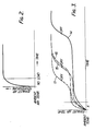
- Fig. 2 shows the way in which exhaust air temperature increases with time in the case in which the dryer is empty. Air incoming to the drum from the air heater merely heats up the drum and adjacent components of the dryer and consequently the exhaust air temperature shows an initial rapid increase followed by a steady condition.
- Fig. 3 shows the relationship with time of changes in the exhaust air temperature for several different loads of articles made of cotton.
- Curves 15, 16 and 17 show respectively the relationship for a 4 kg (dry weight) load of cotton articles with, initially, a 50% (by weight) water content, a 2 kg (dry weight) load of cotton articles with, initially, a 100% (by weight) water content, and, a 2 kg (by weight) load of cotton articles with, initially, a 50% (by weight) water content.
- curve 16 rises initially at a larger rate of increase than curve 15, both having the same 2 kg content of water to be evaporated, in fact a slightly longer, nor shorter, drying time is required for the smaller dry weight of articles. This is because the smaller weight of articles makes less efficient use of the hot air passing through the drum of the dryer, and consequently the drop in temperature from the temperature at which the air enters the drum is less and the plateau temperature is slightly higher.
- the microprocessor will endeavour to anticipate the plateau temperature from the initial shape of the temperature/time curve, an early large rate of increase in exhaust air temperature followed by a more rapid decline in the rate of increase will indicate a lower plateau temperature than the same early rate of increase followed by a less rapid decline in the rate of increase.
- time will have to subsequently be detracted by the control from the time first calculated to switch off the heater, should the plasteau temperature be less than the assumed temperature programmed into the microprocessor for any given heat input, air throughput, ambient temperature and so on.
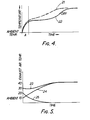
- Fig. 4 shows the exhaust air temperature/time relationship for 2 kg (dry) weight with 100% (by weight) initial water content of articles made of nylon - curve 21, and of acrylic fibers - curve 22.
- the points X on the curves indicate the dry condition and it will be noted that the time to reach that condition is different for the different materials.
- Fig. 5 illustrates the dependence. If the dryer is "hot" at the commencement of a drying cycle, the exhaust air temperature will start from a higher value but will in due course, rise to the said final temperature as if the starting temperature was that of ambient air.
- curve 23 relates exhaust air temperature and time for the case in which the starting exhaust air temperature is 30°C.
- Curve 23 can be compared with curve 24 which relates exhaust air temperature and time for the case in which the starting exhaust air temperature is 10°C.
- the curve 23 condition must be recognised by the microprocessor so that the latter can apply a correction to the sensing base from which the microprocessor calculates the heating time and the overall cycle duration of the dryer which may take the form of a decreasing deduction from the sensed value of the exhaust air temperature as indicated by curve 25, the deduction being the curve 23 value minus the curve 24 value.
- the correct time to reach dryness must be based on the curve from the point at which the exhaust temperature has risen to the ambient value, thereafter the curve will be identical with that of articles loaded whilst at ambient temperature.
- the microprocessor must respond to the drop in sensed exhaust air temperature and make the appropriate correction.
- the microprocessor is programmed to scan or otherwise monitor the rate of increase in exhaust air temperature at specified intervals of time during the initial heat up period - time period A.
- the microprocessor is also programmed with a series of cycle durations corresponding with a variety of different exhaust air temperatures and times of occurrence of such temperatures. These cycle durations will be not only those required to bring the articles to a "dry" condition but will also include cycle durations to reach various conditions of damp dry.
- the exhaust air temperature is checked at specified intervals of 0.5 sec for the first 5 sec after the start of a drying cycle.
- the microprocessor will deduce from the averaged or aggregated exhaust temperature readings that the cycle duration is, say 2 hours. That duration is displayed in a mode characterizing an unconfirmed time because the time is likely to be an approximation only, because at the commencement of a cycle, the exhaust air temperature/time curves, as can be seen from Fig. 3, are very close together. However, as more readings become available greater certainty is possible and after about 60 seconds a reasonably accurate cycle duration is available.
- the displayed time includes "cold" run of 10 min.
- checking continues every 0.5 sector a further period of 10 sec (15 sec runs time).
- the microprocessor determines and stores the average value of the temperatures at each 0.5 sec interval, or aggregates those temperatures.
- the microprocessor will then up-date the first assessed cycle duration time and display, in the unconfirmed mode, the up-dated time including the 10 min "cold" run.
- the initial duration deduced would be programmed to be the longest that would be required, to be corrected at a later stage.
- the correction made might be of the order of a 5 minute reduction in the time during which the heater is energized, but no reduction will be made in the total time to run of the dryer.
- Monitoring of exhaust air temperature may cease after a predetermined time programmed into the microprocessor or it may continue as will be described below.
- the deduced cycle time is also displayed on the display 13 - preferably a digital display showing minutes only or hours and minutes.
- the display would be energised after 5 sec to show 2:00 hours.
- an additional symbol is energized, for example the colon separating the hours and minutes in the display is caused to flash - this is referred to as the "unconformed mode".
- the deduced duration may change and this can be indicated to the user as such changes take place, i.e. by a constantly changing display or by one single change at the end of the 60 sec period.
- the colons would cease flashing at the end of that period - the display then being in the confirmed mode.
- cycle duration Once the cycle duration has stabilised, its value is stored to allow the microprocessor to produce, at the approximate time, outputs to terminate the drying cycle. Two outputs are normally required because the air heater is de-energised before the drying cycle ends, the remainder of the cycle being simply the conventional "cool-down" period during which cool air is circulated through the drum to cool articles therein.
- the microprocessor may also be programmed to reduce the heater to a half-heat condition at an appropriate point in the cycle. This will reduce the possibility of overheating articles made from that material.
- Changes in ambient temperature and any other changes, for example supply voltage, may be caused to adjust the effect of exhaust air temperature readings either before such readings are inputted to the microprocessor or within the latter.
- Inputs 9, 9a, 10 and 11 may operate in a similar fashion.
- Adjustment of input 12 makes an appropriate adjustment to the time within a cycle that the air heater is energised, the microprocessor having been programmed to terminate energisation in accordance with the adjustment of the input 12 and the state of dryness indicated thereby.
- a user first loads the machine with articles to be tumble dried and then sets the control in accordance with the nature of the material from which the articles are made. Control 12 is then set in accordance with the state of dryness required. Once the door giving access to the drum is closed, the machine may be energised and may commence the tumble dry cycle.
- the machine may incorporate some only of the features mentioned above. For example, only exhaust air temperature may be monitored, fixed values being assumed for ambient air temperature, inlet air temperature supply voltage and element loading. In addition, it may be possible to distinguish between acrylic and other materials only.
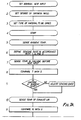
- Figs. 7A, B, C and 8 are flow diagrams showing in more detail the procedure described above.
- the convention adopted employs blocks with round ends to designate inputs to and outputs from the microprocessor, rectangular blocks to designate non-decision operations which are carried out and diamond-shaped blocks to represent interrogations.
- Step 1 in the diagram of Fig. 7 is normally affected during factory testing of the dryer but steps 2 and 3 are carried out by the user as explained above.
- Rectangular blocks carrying the text "adjust sensing base” indicate that a sensed variation from standard of the parameter is used to adjust the value to be used in step 11.
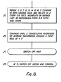
- Fig. 8 is an alternative to the automatic de- energisation of the air heater attime T-10 min, it is possible to employ a microprocessor programmed to terminate air heating when the rise in exhaust air temperature exceeds a predetermined value and to monitor exhaust air temperature throughout the drying cycle or at least for that part thereof during which the air heater is energised.
- monitoring of exhaust air temperature is continued after the 5 min period mentioned above, checks on the temperature occurring ever 5 sec.
- a temperature trend can be established and when this indicates an increase of a preselected value, the air heater is de-energised. Tumbling then continues under "cool" incoming air conditions until time T is reached when the drum motor is switched off.
- tumble dryer may be embodied as a combined washing machine and tumble dryer.
Landscapes
- Engineering & Computer Science (AREA)
- Textile Engineering (AREA)
- Control Of Washing Machine And Dryer (AREA)
Claims (9)
Applications Claiming Priority (2)
| Application Number | Priority Date | Filing Date | Title |
|---|---|---|---|
| GB8107777 | 1981-03-12 | ||
| GB8107777 | 1981-03-12 |
Publications (2)
| Publication Number | Publication Date |
|---|---|
| EP0060698A1 EP0060698A1 (fr) | 1982-09-22 |
| EP0060698B1 true EP0060698B1 (fr) | 1986-06-25 |
Family
ID=10520336
Family Applications (1)
| Application Number | Title | Priority Date | Filing Date |
|---|---|---|---|
| EP82301282A Expired EP0060698B1 (fr) | 1981-03-12 | 1982-03-12 | Sécheur à tambour |
Country Status (2)
| Country | Link |
|---|---|
| EP (1) | EP0060698B1 (fr) |
| DE (1) | DE3271818D1 (fr) |
Families Citing this family (11)
| Publication number | Priority date | Publication date | Assignee | Title |
|---|---|---|---|---|
| FR2632986B1 (fr) * | 1988-06-17 | 1991-08-16 | Ciapem | Seche-linge commande par microprocesseur |
| FR2639369B1 (fr) * | 1988-11-24 | 1990-12-28 | Ciapem | Seche-linge muni d'un systeme de commande automatique de fonctionnement |
| CA2032857A1 (fr) * | 1990-01-02 | 1991-07-03 | Larry Thomas Bashark | Diagnostique et controle electronique d'elements chauffant de seche-linge |
| EP0573703A1 (fr) * | 1992-06-10 | 1993-12-15 | Whirlpool Europe B.V. | Procédé pour optimiser le séchage dans un sèche linge ou similaire et machine utilisant ce procédé |
| IT1267590B1 (it) * | 1994-10-11 | 1997-02-07 | Zanussi Elettrodomestici | Asciugabiancheria con dispositivi perfezionati per la determinazione del tempo di asciugatura |
| DE4442250C2 (de) * | 1994-11-28 | 2000-01-05 | Bsh Bosch Siemens Hausgeraete | Verfahren zum Bestimmen der voraussichtlichen Trockenzeit in einem Wäschetrockner |
| DE4447270A1 (de) * | 1994-12-30 | 1996-07-04 | Bosch Siemens Hausgeraete | Verfahren zum Steuern von Trockenvorgängen in Haushalt-Wäschetrocknern |
| DE19719661C2 (de) * | 1997-05-09 | 2002-09-12 | Miele & Cie | Verfahren zur Steuerung des Restfeuchtegehaltes der Wäsche in einem programmgesteuerten Wäschetrockner |
| KR20050119268A (ko) * | 2004-06-16 | 2005-12-21 | 삼성전자주식회사 | 건조기 및 건조시간 표시방법 |
| US8555522B2 (en) * | 2010-10-21 | 2013-10-15 | Whirlpool Corporation | Laundry treating appliance with inlet temperature compensation |
| US9080283B2 (en) | 2011-10-06 | 2015-07-14 | Whirlpool Corporation | Method to control a drying cycle of a laundry treating appliance |
Family Cites Families (6)
| Publication number | Priority date | Publication date | Assignee | Title |
|---|---|---|---|---|
| DE2530580A1 (de) * | 1975-07-09 | 1977-01-20 | Miele & Cie | Automatischer waeschetrockner |
| GB1572618A (en) * | 1977-03-24 | 1980-07-30 | Thorn Domestic Appliances Ltd | Air driers and control circuits therefor |
| US4206552A (en) * | 1978-04-28 | 1980-06-10 | Mallory Components Group Emhart Industries, Inc. | Means and method for controlling the operation of a drying apparatus |
| SE7810894L (sv) * | 1978-10-19 | 1980-04-20 | Junga Verksteder Ab | Torktumlare |
| DE2930671C2 (de) * | 1979-07-28 | 1986-02-06 | AKO-Werke GmbH & Co KG, 7988 Wangen | Einrichtung zur Steuerung der Heizung in einem Wäschetrockner |
| FR2482143A1 (fr) * | 1980-05-06 | 1981-11-13 | Thomson Brandt | Seche-linge a programmation electronique |
-
1982
- 1982-03-12 EP EP82301282A patent/EP0060698B1/fr not_active Expired
- 1982-03-12 DE DE8282301282T patent/DE3271818D1/de not_active Expired
Also Published As
| Publication number | Publication date |
|---|---|
| EP0060698A1 (fr) | 1982-09-22 |
| DE3271818D1 (en) | 1986-07-31 |
Similar Documents
| Publication | Publication Date | Title |
|---|---|---|
| CA2373976C (fr) | Systeme de seche-linge autoprogrammable | |
| US20090313848A1 (en) | Method and household appliance for drying wet laudry | |
| US4827627A (en) | Apparatus and method for controlling a drying cycle of a clothes dryer | |
| US4397101A (en) | Automatic dryer control | |
| US7975401B2 (en) | Apparatus and method for controlling a clothes dryer | |
| EP2458076B1 (fr) | Sèche-linge à tambour rotatif et procédé de contrôle d'un sèche-linge à tambour rotatif pour sécher le linge délicat | |
| US8112902B2 (en) | Method for determining the load quantity in a spin dryer and spin dryer | |
| US6446357B2 (en) | Fuzzy logic control for an electric clothes dryer | |
| GB2296793A (en) | Method of contrplling drying operation of a drier | |
| US4763425A (en) | Automatic clothes dryer | |
| US7080464B1 (en) | Detection of synthetic fabric loads in an automatic dryer | |
| CA2390660C (fr) | Systeme de commande pour secheuse automatique | |
| US4257170A (en) | Tumbler dryer | |
| EP2458078B1 (fr) | Sèche-linge à tambour rotatif et procédé de contrôle d'un sèche-linge à tambour rotatif | |
| US11414811B2 (en) | Apparatus for treating laundry and controlling method thereof | |
| EP0060698A1 (fr) | Sécheur à tambour | |
| US10151061B1 (en) | Dryer appliances and methods of operation | |
| US20080184588A1 (en) | Auto coin | |
| EP1236826A2 (fr) | Procédé pour changer le programme dans un sèche-linge domestique | |
| US11346043B2 (en) | Dryer appliance and a method of operating the same in response to restricted air flow | |
| KR101024920B1 (ko) | 자동 건조 드럼 세탁기의 제어 방법 | |
| EP3842587B1 (fr) | Machine à sécher le linge | |
| JPH0411675Y2 (fr) | ||
| JPH0412800A (ja) | 乾燥機の制御装置 | |
| JPH0411674Y2 (fr) |
Legal Events
| Date | Code | Title | Description |
|---|---|---|---|
| PUAI | Public reference made under article 153(3) epc to a published international application that has entered the european phase |
Free format text: ORIGINAL CODE: 0009012 |
|
| AK | Designated contracting states |
Designated state(s): DE FR GB IT NL SE |
|
| 17P | Request for examination filed |
Effective date: 19830304 |
|
| GRAA | (expected) grant |
Free format text: ORIGINAL CODE: 0009210 |
|
| AK | Designated contracting states |
Kind code of ref document: B1 Designated state(s): DE FR GB IT NL SE |
|
| PG25 | Lapsed in a contracting state [announced via postgrant information from national office to epo] |
Ref country code: NL Effective date: 19860625 Ref country code: IT Free format text: LAPSE BECAUSE OF FAILURE TO SUBMIT A TRANSLATION OF THE DESCRIPTION OR TO PAY THE FEE WITHIN THE PRESCRIBED TIME-LIMIT;WARNING: LAPSES OF ITALIAN PATENTS WITH EFFECTIVE DATE BEFORE 2007 MAY HAVE OCCURRED AT ANY TIME BEFORE 2007. THE CORRECT EFFECTIVE DATE MAY BE DIFFERENT FROM THE ONE RECORDED. Effective date: 19860625 Ref country code: FR Free format text: THE PATENT HAS BEEN ANNULLED BY A DECISION OF A NATIONAL AUTHORITY Effective date: 19860625 |
|
| PG25 | Lapsed in a contracting state [announced via postgrant information from national office to epo] |
Ref country code: SE Effective date: 19860630 |
|
| REF | Corresponds to: |
Ref document number: 3271818 Country of ref document: DE Date of ref document: 19860731 |
|
| EN | Fr: translation not filed | ||
| NLV1 | Nl: lapsed or annulled due to failure to fulfill the requirements of art. 29p and 29m of the patents act | ||
| PLBE | No opposition filed within time limit |
Free format text: ORIGINAL CODE: 0009261 |
|
| STAA | Information on the status of an ep patent application or granted ep patent |
Free format text: STATUS: NO OPPOSITION FILED WITHIN TIME LIMIT |
|
| 26N | No opposition filed | ||
| REG | Reference to a national code |
Ref country code: GB Ref legal event code: 732 |
|
| PG25 | Lapsed in a contracting state [announced via postgrant information from national office to epo] |
Ref country code: GB Effective date: 19890312 |
|
| GBPC | Gb: european patent ceased through non-payment of renewal fee | ||
| PG25 | Lapsed in a contracting state [announced via postgrant information from national office to epo] |
Ref country code: DE Effective date: 19891201 |