EP0060701A2 - Verfahren und Apparat zur Regelung der Nulladjustierung von Gewichtssensoren - Google Patents
Verfahren und Apparat zur Regelung der Nulladjustierung von Gewichtssensoren Download PDFInfo
- Publication number
- EP0060701A2 EP0060701A2 EP82301287A EP82301287A EP0060701A2 EP 0060701 A2 EP0060701 A2 EP 0060701A2 EP 82301287 A EP82301287 A EP 82301287A EP 82301287 A EP82301287 A EP 82301287A EP 0060701 A2 EP0060701 A2 EP 0060701A2
- Authority
- EP
- European Patent Office
- Prior art keywords
- zero
- weight
- articles
- point deviation
- zero point
- Prior art date
- Legal status (The legal status is an assumption and is not a legal conclusion. Google has not performed a legal analysis and makes no representation as to the accuracy of the status listed.)
- Granted
Links
- 238000000034 method Methods 0.000 title claims abstract description 18
- 230000002401 inhibitory effect Effects 0.000 claims abstract 5
- 238000005303 weighing Methods 0.000 claims description 92
- 238000010586 diagram Methods 0.000 description 4
- 238000012856 packing Methods 0.000 description 4
- 239000000843 powder Substances 0.000 description 4
- 150000003839 salts Chemical class 0.000 description 4
- 239000012634 fragment Substances 0.000 description 3
- 229920000297 Rayon Polymers 0.000 description 1
- 230000005856 abnormality Effects 0.000 description 1
- 235000009508 confectionery Nutrition 0.000 description 1
- 238000007796 conventional method Methods 0.000 description 1
- 238000007599 discharging Methods 0.000 description 1
- 235000013399 edible fruits Nutrition 0.000 description 1
- 235000013372 meat Nutrition 0.000 description 1
- 230000000717 retained effect Effects 0.000 description 1
Images


Classifications
-
- G—PHYSICS
- G01—MEASURING; TESTING
- G01G—WEIGHING
- G01G23/00—Auxiliary devices for weighing apparatus
- G01G23/18—Indicating devices, e.g. for remote indication; Recording devices; Scales, e.g. graduated
- G01G23/36—Indicating the weight by electrical means, e.g. using photoelectric cells
- G01G23/37—Indicating the weight by electrical means, e.g. using photoelectric cells involving digital counting
-
- G—PHYSICS
- G01—MEASURING; TESTING
- G01G—WEIGHING
- G01G23/00—Auxiliary devices for weighing apparatus
- G01G23/14—Devices for determining tare weight or for cancelling out the tare by zeroising, e.g. mechanically operated
-
- G—PHYSICS
- G01—MEASURING; TESTING
- G01G—WEIGHING
- G01G23/00—Auxiliary devices for weighing apparatus
- G01G23/14—Devices for determining tare weight or for cancelling out the tare by zeroising, e.g. mechanically operated
- G01G23/16—Devices for determining tare weight or for cancelling out the tare by zeroising, e.g. mechanically operated electrically or magnetically operated
- G01G23/166—Devices for determining tare weight or for cancelling out the tare by zeroising, e.g. mechanically operated electrically or magnetically operated involving comparison with a reference value
Definitions
- This invention relates to a method and apparatus for controlling the zero adjustment of a weighing machine used in a combinatorial scale.
- a computer scale as illustrated in Fig. 1, is composed of a plurality of weighing machines A 1 , A 2 , ...., A n , weighing hoppers B 1 , B 2 , ..., B n associated with respective ones of the weighing machines, a common guide chute C, a pull hopper D, and buckets E operatively associated with a packing machine or the like.
- each of the weighing hoppers B 1 , B 2 ,..., B n are supplied with articles to be weighed.
- the articles in each hopper are then weighed, and different combinations of the weighed values are added in each weighing cycle, with the number of weighed values in each combination being either arbitrary or predetermined.
- the sum of the weights in each combination is compared with a set target weight, whereby the weight combination that gives the target weight or the value closest thereto is found for each weighing cycle. This combination of weights is referred to as the best combination.
- a wide variety of matter such as powder, oil, salt and other residual orginating from the weighed articles attaches itself to the walls of the weighing hoppers B 1 , B 2t ..., B n . While the amount of such matter left clinging to a weighing hopper is extremely small for one weighing operation by that hopper, the total amount which can accumulate over a large number of weighing operations is significant. Accordingly, a computer scale incorporates an automatic zero adjustment circuit which automatically applies a zero adjustment to the weight sensors associated with the respetive weighing hoppers.
- the automatic zero adjustment circuit is adapted to automatically adjust the zero point of the weight sensor belonging to the weighing hopper which has performed said preset number of weighing operations.
- the zero adjustment referred to here is for the purpose of setting the output value of a weight sensor to zero when the corresponding weighing hopper is empty. This output value of the weight sensor when the hopper is empty is referred to as the zero point deviation.
- the articles which are to be weighed exhibit a viscose or sticky property and have a relatively large unit weight namely the weight of an individual article, such as pieces of uncooked meat.
- weighing such articles there are instances where several pieces or portions thereof attach themselves to the walls of a weighing hopper, as occurs with the various residua mentioned above.
- the conventional method of zero adjustment cannot distinguish between their attachment to the hoppers and the attachment of the abovementioned residua, so that the same zero adjustment is applied to the weight sensor in both case.
- the weighing hopper whose weight sensor is zero-adjusted has an article or portion thereof clinging to it, weight can be sensed correctly by the sensor only as long as the article remains attached. Since the clinging article or portion is comparatively heavy, however, it will almost never remain attached to the hopper permanently but will eventually fall after repeated weighing operations together with the other articles which are released from the hopper. It is obvious that an error will result when the zero adjustment is applied with articles or fragments thereof clinging to a weighing hopper, followed by the dislodging and dropping of said articles or fragments into the chute C.
- the output of the weight sensor belong to the weighing hopper from which the clinging matter has fallen will include an error w 0 which will prevail until the next zero adjustment, the error w 0 representing the weight of the formerly attached matter.
- the conventional zero adjustment method in other words, there are cases where weighing cannot be performed with a high level of accuracy.
- an object of the present invention is to provide a method and apparatus for applying a zero adjustment to a weight sensor so that a weighing operation can be performed with great accuracy not only when residua such as powder, oil and salt which originate from the articles to be weighed attach themselves to the walls of a weighing hopper, but also when some of the articles themselves or fragments thereof become attached to the weighing hopper.
- Another object of the present invention is to provide a method and apparatus for applying a zero adjustment to a weight sensor to prevent a significant deviation in the zero point when, following a zero adjustment which is performed while articles are clinging to a weighing hopper, said articles are dislodged and fall from the hopper.
- Still another object of the present invention is to provide a method and apparatus for applying a zero adjustment to a weight sensor in such a manner that it is possible to distinguish between a variation in the zero point of the weight sensor caused by residua such as powder, oil or salt which originate from the articles to be weighed and which attach themselves to a weighing hopper, and a variation in the zero point of the weight sensor caused when the articles themselves become attached to the walls of the weighing hopper, whereby it is possible to execute a prescribed zero adjustment operation which conforms to the particular zero point variation.
- residua such as powder, oil or salt
- Yet another object of the present invention is to provide a zero adjustment method and apparatus through which the operator is informed of the fact that articles are clinging to a weighing hopper by arranging it so that an alarm is issued when articles attach themselves to the hopper, or when the variation in the zero point remains unduly large even after the zero adjustment operation has been inhibited a predetermined number of times.
- the foregoing and other objects are attained by providing a zero adjustment method and apparatus which utilize the fact that the attachment of the articles themselves to the walls of a weighing hopper gives rise to a variation in the zero point which is more sudden and pronounced then that which results when residua such as powder, oil or salt given off by the articles become attached to the hopper, the zero point variation in this latter case being comparatively gentle.
- the limits of the zero point deviation namely the output of a weight sensor whose corresponding hopper is empty
- the zero point deviation of a particular weight sensor is found to exceed these limits, this is regarded as indicating that an article(s) is attached to the hopper.
- the arrangement is such that either an alarm is issued or the zero adjustment operation inhibited.
- MS denotes a main feeder of vibratory conveyance type.
- Articles to be weighed which will be referred to hereinafter merely as “articles”, are introduced into the main feeder MS and imparted with vibratory motion so as to be dispersed radially outward from the center of the main feeder.
- CN, CN,... denote n-number of weighing sections which are arranged around the main feeder MS along radially extending lines to receive the articles dispersed by the main feeder.
- Each weighing section CN includes a a dispersing feeder CN a , a holding vessel CN b , a holding vessel gate CN c , a weighing hopper CN d , a weight sensor CN e , and a weighing hopper gate CN f .
- the dispersing feeder CN a comprises an independently vibratable conveyance device for feeding the articles by means of vibration, or an independently operable shutter device for delivering the articles in batches. In either case, each dispersing feeder CN a is so arranged that the articles received from the centrally located main feeder MS can be introduced into the corresponding holding vessel eNb disposed therebelow.
- the holding vessel gate CN c is provided on each holding vessel CN b in such a manner that the articles received in the holding vessel are released into the weighing hopper CN d when the gate CN c is opened.
- Each weight sensor CPd e is attached to the corresponding weighing hopper CN d and is operable to measure the weight of the articles introduced into the weighing hopper.
- the weight sensor CN is adapted to supply a combination control unit (not shown) with an electrical signal indicative of the measured weight. The combination control unit then selects the optimum combination of articles that gives a total weight closest to a target weight.
- Each of the weighing hopper gates CN f is provided on the corresponding weighing hopper CN d .
- the combination control unit upon receiving the signals from each of the weight sensors CN e , responds by opening the weighing hopper gates CN 5 only of those weighing hoppers CN d that will give the optimum combination of articles, as mentioned above.
- the articles from the weighing hoppers CN d selected in this manner fall through the open weighing hopper gates and are discharged into a common collecting chute GS where they are collected together.
- the collecting chute GS has the shape of a funnel and is so arranged as to receive the articles from any of the circularly arrayed weighing hoppers CN d via the hopper gates, which are located above the funnel substantially along its outer rim.
- the articles received by the collecting chute GS are collected at the centrally located lower end thereof by falling under their own weight or by being forcibly shifted along the inclined wall of the funnel by a mechanical scraper or the like, which is not shown.
- the collecting chute GS is provided with a timing hopper THP at the lower end thereof for temporarily holding the collected articles.
- the arrival of an externally applied signal from a packing device or the like causes the timing hopper THP to release the retained articles from the weighing apparatus, namely from collecting chute GS which constitutes the lowermost stage of the apparatus, to a separate item of equipment, such as the packing device.
- the holding vessels CN b and weighing hoppers CN d contain a supply of the articles.
- the weight sensors CN associated with the respective weighing hoppers CN d measure the weights of the articles in each hopper and produce weight values W 1 through W 10 which are sent to the combination control unit, not shown.
- the control unit performs an arithmetic combinatory control operation using the weight values W 1 through W 10 and selects the combination of articles that gives a total weight closest to the set target weight.
- a drive control unit (not shown) opens the weighing hopper gates CN f which are selected on the basis of the best combination, whereby the selected weighing hoppers discharge their articles into the collecting chute GS.
- the holding vessel gates CN C of those holding vessels CN b corresponding to the empty weighing hoppers CN d are opened to introduce a fresh supply of the articles into said weighing hoppers, leaving said holding vessels empty.
- the dispersing feeders CN a which correspond to the empty holding vessels CN b are vibrated for a predetermined period of time to deliver a fresh supply of the articles to said holding vessels. This restores the weighing apparatus to the initial state to permit resumption of the control operation for selecting the optimum weight combinations in the manner described.
- weighing by the combinatorial scale may proceed in continuous fashion by repeating the foregoing steps.
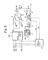
- Fig. 3 illustrates a preferred embodiment of a zero adjustment control apparatus according to the present invention.
- the apparatus includes a channel selection circuit 1 for selecting which of the plurality of weight sensors CN e , CN e ,... is to be subjected to a zero adjustment.
- Fig. 4 is a block diagram which illustrates the channel selection circuit 1 in greater detail.
- the channel selection circuit 1 is shown to include a decoder 1a for decoding a best combination code CCS provided by a combination control unit which is not shown, a bank of counters 1b, 1b, ... provided for respective ones of the weight sensors CN e , CN e ,..., a gate 1c which opens to deliver a timing pulse TP in response to the generation of the best combination code CCS (that is, when a corresponding signal CCS' goes to logical "1"), an address counter 1d which counts the timing pulses TP to produce an address signal ADR, a multiplexer 1e for delivering the numerical value Mi from the particular counter 1b specified by the address signal ADR, a preset switch 1f in which a predetermined numerical value M is preset, a comparator 1g for comparing the numerical value M s and the output M i of the multiplexer 1e and for producing a coincidence signal COI when M s and Mi coincide, and a multiplexer 1h operable when the
- the code 0100100111 indicates a combination made up of the second, fifth, eight, ninth and tenth weighing hoppers or weight sensors.
- the best combination code CCS is decoded by the decoder 1a to count up, by one step (i.e., +1), the numerical value in those counters 1b, 1b,... corresponding to the weighing hoppers which have been selected as giving the best combination.
- the corresponding signal CCS' goes to logical "1", opening the gate 1c so that the address counter 1d may start counting the timing pulses TP.
- the multiplexer 1e responding by supplying the comparator 1g with the numerical value M1, M 2 , ..., M n from the counter 1b, 1b,... specified by the address signal ADR, which counter corresponds to the 1st, 2nd,..., n-th weight sensor CN e , CN e ,..., CN e .
- the comparator 1g Upon re-charving the designated numerical value M i from the multiplexer 1e, the comparator 1g compares M i with the numerical value M s set in the preset switch 1f and, when they coincide, produces the coincidence signal COI and clears the counter which stores the value M i .
- the multiplexer 1h responds to the coincidence signal COI by delivering the output data (the zero point deviation) D i of the weight sensor CN e designated by the address signal ADR.
- the channel selection circuit 1 is so arranged that when a certain weighing hopper is selected a preset number of times M s (set in switch 1f) as being one which contributes to the best combination, the weight sensor associated with said hopper is designated and its output data, namely the zero point deviation Di, is delivered to the circuitry connected to the output side of the selection circuit 1.
- the zero adjustment control apparatus further includes comparators 2, 3 which receive the zero point deviation D i obtained from the weight sensor CN e selected by the channel selection circuit 1 in the manner described above.
- the comparators 2, 3 compare the magnitude of the zero point deviation Di with preset error limits -w and +w (in grams), respectively.
- a first AND gate 4 receives the output signals of the comparators 2, 3 and produces a pulse when these two outputs coincide. More specifically, the first AND gate 4 develops an output S 4 only when the zero point deviation D i from the selected weight sensor CN e is smaller than +w grams and larger than -w grams.
- the output S 4 of the AND gate 4 is applied to an OR gate 5 whose output S 5 is in turn connected to a second AND gate 6 which receives also a comparison end signal S 1 generated upon the completion of the comparison operation mentioned above.
- the AND gate 6 takes the AND of signals S 1 , S 5 .
- a third AND gate 7 receives the output S 5 of the OR gate 5 after inversion by an inverter 8, as well as the comparison end signal S 1 , and is adapted to take the AND of these two signals.
- An R-S flip-flop 9 is cleared by the outputs S 6 of the second AND gate 6 and set by the output S 7 of the third AND gates 7 to produce a zero adjustment inhibit signal S 2'
- a counter 10 counts the number of times the zero adjustment inhibit signal S 2 is produced by the flip-flop 9.
- the counter 10 is cleared by the output S 6 of the second AND gate 6.
- a preset switch 11 is provided for setting a numerical value N which is applied to a comparison circuit 12 along with the output of the counter 10.
- the comparison circuit 12 issues an alarm signal S 3 when the numerical value N from the preset switch 11 and the numerical value supplied by the counter 10 coincide.
- Designated at numeral 13 is an automatic zero adjusting circuit which will be described in greater detail with reference to Fig. 5.
- the automatic zero adjusting circuit 13 is shown to include n-number of registers 13a, 13a,... provided for respective ones of the weight sensors CN e , CN e ,..., a counter 13b for generating all possible combinations of the n-number of weight sensors CN , CN ,..., these combinations being 2 n- 1 in number, multiplexers 13c, 13d, 13e, and an arithmetic circuit 13f.
- the registers 13a, 13a,... store the zero point deviations obtained from the corresponding weight sensors CN e , CN e ,..., CN e .
- the automatic zero adjusting circuit 13 operates in the following manner.
- the zero point deviation D i from the particular weight sensor CN e designated by the address signal ADR (Fig. 4) is planted in the register 13a corresponding to this weight sensor to update the contents of the register.
- the zero adjustment inhibit signal S 2 arrives from the flip-flop 9, however, none of the registers 13 is updated.
- the result of updating the register is that, in an arithmetic combinatory control operation for providing the best combination, the zero point deviation D i stored in a register 13a is subtracted from the weight value W i of the articles measured by the corresponding weight sensor CN e .
- a zero adjustment is automatically performed in which the difference obtained by subtracting Di from Wi is delivered as the true measured value. This will now be described in further detail.
- the counter 13b generates a pattern BTP of all possible 2 n- 1 combinations. That is, for n-number of weighing hoppers (weight sensors), n combinations are possible when each combination is composed of one weighing hopper, n(n-1)/2: combinations are possible when each combination is composed of two weighing hoppers, and, in general, n(n-1) (n-2) ... (n-r+1)/r: combinations are possible when each combination is composed of r-number of weighing hoppers. Thus the total number of different combinations which can be formed is 2 n- 1.
- the bit pattern will be an indication of the abovementioned combination pattern BTP.
- the combination pattern BTP is applied to the multiplexers 13d, 13e, as illustrated in Fig. 5.
- the multiplexer 13d responds to the particular combination pattern BTP by selecting the specified zero point deviations D i stored in predetermined ones of the registers 13a, these values of D. being delivered to the arithmetic circuit 13f.
- the arithmetic circuit 13f will receive the outputs W 1 , W 2 W 4' W 6' W 10 of the weight sensors CN e associated with the first, second, fourth, sixth and tenth weighing hoppers, and the zero point deviations D 1 , D 2 , D 4 , D 6 , D 10 of said weight sensors.
- the arithmetic circuit 13f is adapted to perform the subtractions W 1 -D 1 , W 2 -D 2 , W 4 -D 4 , W 6 -D 6 , W 10 -D 10 , and to send the results to a combinatory arithmetic unit, which is not shown.
- a single cycle proceeds as follows.
- a weight sensor CN e which requires a zero adjustment is selected by the channel selection circuit 1
- the zero point deviation D i from the selected weight sensor is applied to the comparators 2, 3.
- the comparators 2, 3 compare the magnitude of the received zero point deviation D i with the preset allowable zero point deviation limits -w grams and +w grams.
- the comparator 2 produces a pulse when the zero point deviation Di is smaller than w grams, and the comparator 3 when the.absolute value
- the zero point deviation D i which is the output, of the selected weight sensor is within the range -w to +w, therefore, the output S 4 of the first AND gate 4 goes to logical "1".
- the channel selection circuit 1 delivers the next zero point deviation on the basis of which the foregoing comparison operation and associated processing take place. This is repeated each time the channel selection circuit 1 delivers a zero point deviation D i .
- the content of counter 10 attains the numerical value N which has been preset in the preset switch 11, this is sensed by the comparison circuit 12 which responds by generating the alarm signal S 3 .
- the present invention as described and illustrated hereinabove is so arranged that when a weighing machine having an automatic zero adjustment apparatus is subjected to a zero adjustment, the variation in the zero point is investigated to determine whether it lies within preset limits. When it does lie within these limits the zero adjustment is allowed to proceed; when it does not the zero adjustment is inhibited. Accordingly, when an article is clinging to a weighing hopper to give rise to a significant shift in the zero point at the time of a zero adjustment, said zero adjustment is not allowed to occur. This makes it possible to prevent a significant shift in the zero point when, following a zero adjustment which is performed while articles are clinging to a weighing hopper, said articles are dislodged and fall from the hopper.
- an alarm is issued to notify the operator of an abnormality wherein an article clings to a weighing hopper without falling for a certain period of time, as indicated by the generation of a predetermined number (including just one) of zero adjustment inhibit signals.
Landscapes
- Physics & Mathematics (AREA)
- General Physics & Mathematics (AREA)
- Weight Measurement For Supplying Or Discharging Of Specified Amounts Of Material (AREA)
- Indication And Recording Devices For Special Purposes And Tariff Metering Devices (AREA)
Applications Claiming Priority (2)
| Application Number | Priority Date | Filing Date | Title |
|---|---|---|---|
| JP37061/81 | 1981-03-14 | ||
| JP56037061A JPS57151828A (en) | 1981-03-14 | 1981-03-14 | Automatic zero point adjustment prohibitor |
Publications (3)
| Publication Number | Publication Date |
|---|---|
| EP0060701A2 true EP0060701A2 (de) | 1982-09-22 |
| EP0060701A3 EP0060701A3 (en) | 1984-10-10 |
| EP0060701B1 EP0060701B1 (de) | 1988-06-15 |
Family
ID=12487037
Family Applications (1)
| Application Number | Title | Priority Date | Filing Date |
|---|---|---|---|
| EP82301287A Expired EP0060701B1 (de) | 1981-03-14 | 1982-03-12 | Verfahren und Apparat zur Regelung der Nulladjustierung von Gewichtssensoren |
Country Status (5)
| Country | Link |
|---|---|
| US (1) | US4442911A (de) |
| EP (1) | EP0060701B1 (de) |
| JP (1) | JPS57151828A (de) |
| AU (1) | AU531511B2 (de) |
| DE (1) | DE3278674D1 (de) |
Cited By (5)
| Publication number | Priority date | Publication date | Assignee | Title |
|---|---|---|---|---|
| EP0124355A3 (en) * | 1983-04-27 | 1985-12-18 | Kabushiki Kaisha Ishida Koki Seisakusho | Zero-adjustment in weighing apparatus |
| US4871038A (en) * | 1987-03-09 | 1989-10-03 | Driver Southall Limited | Combinational weighing systems |
| EP0365097A1 (de) * | 1988-10-21 | 1990-04-25 | Locs B.V. | System zum Verhindern von Betrug beim Gebrauch eines Taxameters |
| EP0281797A3 (de) * | 1984-10-26 | 1990-05-16 | Ishida Scales Mfg. Co., Ltd. | Eine Einheit zum Justieren des Nullpunktes für einen Wägeapparat |
| EP0897105A1 (de) * | 1997-08-13 | 1999-02-17 | Ncr International Inc. | Verfahren und Einrichtung zum Tarieren einer Artikelwaage für Abrechnungsterminal im Einzelhandel |
Families Citing this family (20)
| Publication number | Priority date | Publication date | Assignee | Title |
|---|---|---|---|---|
| JPS5952719A (ja) * | 1982-09-20 | 1984-03-27 | Ishida Scales Mfg Co Ltd | 組み合せ計量方式 |
| US4531599A (en) * | 1983-08-01 | 1985-07-30 | Langdon Wales R | Method and apparatus for weighing waste signatures from a printing press |
| DE3578813D1 (de) * | 1984-04-05 | 1990-08-30 | Ishida Scale Mfg Co Ltd | Rechnergestuetzter waegeapparat zur kombinatorischen waegung. |
| JP2552440B2 (ja) * | 1985-05-23 | 1996-11-13 | 株式会社 石田衡器製作所 | 組合せ計量装置又は組合せ計数装置における零点異常排除装置 |
| US4630696A (en) * | 1985-10-25 | 1986-12-23 | Azionaria Costruzioni Macchine Automatiche | Apparatus and method for automatic system calibration to provide enhanced resolution in computerized weighing systems |
| WO1987004239A1 (fr) * | 1985-12-29 | 1987-07-16 | Anritsu Corporation | Appareil de pesage combine |
| US4715457A (en) * | 1986-05-27 | 1987-12-29 | Ncr Corporation | Method for fast weighing |
| US4751661A (en) * | 1986-05-27 | 1988-06-14 | Ncr Corporation | Automatic zero balancing of a weighing apparatus |
| JP2517715B2 (ja) * | 1986-12-11 | 1996-07-24 | 株式会社イシダ | 組合せ計量機 |
| JPS6429709A (en) * | 1987-07-24 | 1989-01-31 | Sharp Kk | Zero point correcting system |
| JPH0658245B2 (ja) * | 1988-06-29 | 1994-08-03 | 株式会社寺岡精工 | 手動式組合せ秤 |
| US5987426A (en) | 1997-10-14 | 1999-11-16 | Ncr Corporation | Point-of-sale system including isolation layer between client and server software |
| US5967264A (en) | 1998-05-01 | 1999-10-19 | Ncr Corporation | Method of monitoring item shuffling in a post-scan area of a self-service checkout terminal |
| US6856964B1 (en) | 1999-03-22 | 2005-02-15 | Ncr Corporation | System and methods for integrating a self-checkout system into an existing store system |
| US6296185B1 (en) | 1999-11-02 | 2001-10-02 | Ncr Corporation | Apparatus and method for operating a checkout system having a display monitor which displays both transaction information and customer-specific messages during a checkout transaction |
| KR100966880B1 (ko) * | 2003-05-14 | 2010-06-30 | 삼성전자주식회사 | 조리장치 |
| JP4578189B2 (ja) * | 2004-09-21 | 2010-11-10 | 大和製衡株式会社 | 組合せ計量装置 |
| CN101915589B (zh) * | 2010-08-19 | 2011-12-14 | 中国航空工业第六一八研究所 | 舵机作动器主控阀传感器调零方法 |
| CN107966197A (zh) * | 2018-01-12 | 2018-04-27 | 成都奥北环保科技有限公司 | 一种智能电子称重系统和方法 |
| CN115790788B (zh) * | 2022-12-12 | 2023-05-30 | 长沙聚睿科技有限公司 | 一种具有偏复位测重传感器 |
Family Cites Families (5)
| Publication number | Priority date | Publication date | Assignee | Title |
|---|---|---|---|---|
| US3805903A (en) * | 1972-05-02 | 1974-04-23 | Triangle Package Machinery Co | Servo control system for filling machine weight setting |
| DE2323750B2 (de) * | 1973-05-10 | 1975-11-13 | Atoma Gmbh, 8264 Waldkraiburg | Wägevorrichtung für kontinuierliche Wägungen |
| US3916173A (en) * | 1974-06-27 | 1975-10-28 | Reliance Electric Co | Plural scale system with digital zero correction |
| US4029162A (en) * | 1975-10-15 | 1977-06-14 | Hobart Corporation | Zero return tare guard |
| US4344492A (en) * | 1980-04-14 | 1982-08-17 | Yamato Scale Co. Ltd. | Automatic combination weighing machine with improved zero-point correction |
-
1981
- 1981-03-14 JP JP56037061A patent/JPS57151828A/ja active Granted
-
1982
- 1982-03-11 AU AU81306/82A patent/AU531511B2/en not_active Ceased
- 1982-03-12 EP EP82301287A patent/EP0060701B1/de not_active Expired
- 1982-03-12 US US06/357,755 patent/US4442911A/en not_active Expired - Lifetime
- 1982-03-12 DE DE8282301287T patent/DE3278674D1/de not_active Expired
Cited By (8)
| Publication number | Priority date | Publication date | Assignee | Title |
|---|---|---|---|---|
| EP0124355A3 (en) * | 1983-04-27 | 1985-12-18 | Kabushiki Kaisha Ishida Koki Seisakusho | Zero-adjustment in weighing apparatus |
| US4661920A (en) * | 1983-04-27 | 1987-04-28 | Kabushiki Kaisha Ishida Koki Seisakusho | Automatic zero-adjustment method and apparatus |
| EP0281797A3 (de) * | 1984-10-26 | 1990-05-16 | Ishida Scales Mfg. Co., Ltd. | Eine Einheit zum Justieren des Nullpunktes für einen Wägeapparat |
| US4871038A (en) * | 1987-03-09 | 1989-10-03 | Driver Southall Limited | Combinational weighing systems |
| EP0365097A1 (de) * | 1988-10-21 | 1990-04-25 | Locs B.V. | System zum Verhindern von Betrug beim Gebrauch eines Taxameters |
| US5121097A (en) * | 1988-10-21 | 1992-06-09 | Locs B.V. | System for preventing fraud in the use of a taximeter |
| EP0897105A1 (de) * | 1997-08-13 | 1999-02-17 | Ncr International Inc. | Verfahren und Einrichtung zum Tarieren einer Artikelwaage für Abrechnungsterminal im Einzelhandel |
| US6080938A (en) * | 1997-08-13 | 2000-06-27 | Ncr Corporation | Method and apparatus for resetting a product scale of a retail checkout terminal |
Also Published As
| Publication number | Publication date |
|---|---|
| US4442911A (en) | 1984-04-17 |
| AU8130682A (en) | 1982-09-23 |
| EP0060701A3 (en) | 1984-10-10 |
| DE3278674D1 (en) | 1988-07-21 |
| JPS57151828A (en) | 1982-09-20 |
| EP0060701B1 (de) | 1988-06-15 |
| JPH0156693B2 (de) | 1989-12-01 |
| AU531511B2 (en) | 1983-08-25 |
Similar Documents
| Publication | Publication Date | Title |
|---|---|---|
| EP0060701A2 (de) | Verfahren und Apparat zur Regelung der Nulladjustierung von Gewichtssensoren | |
| EP0084968B1 (de) | Wägemethode und Vorrichtung hierfür | |
| EP0071473B1 (de) | Kombinatorisches Portionieren von Artikeln | |
| EP0063056B1 (de) | Kombinatorische Wägungsmethode und Apparat dafür | |
| US4494619A (en) | Combinatorial weighing apparatus with bulk and fine feed | |
| US4467880A (en) | Combinatorial weighing apparatus | |
| US4609058A (en) | Combinatorial weighing method and apparatus therefor | |
| US4396078A (en) | Weighing or counting method with some unfilled hoppers | |
| EP0076167B1 (de) | Kombinatorisches Wiegen oder Zählen von Artikeln | |
| EP0074773B1 (de) | Kombinatorisches Wiegeverfahren | |
| EP0103476A2 (de) | Kombinatorische Wägemethode und Apparat hierfür | |
| EP0064554A1 (de) | Verfahren und einrichtung zum wiegen von kombinationen | |
| EP0124370B1 (de) | Kombinatorische Wiegemethode und Apparat | |
| EP0060633B1 (de) | Verfahren und Apparat zur kombinatorischen Wägung | |
| US4512427A (en) | Combinatorial weighing method and apparatus | |
| EP0125080B1 (de) | Kombinatorische Wiegemethode und Apparat | |
| US4574897A (en) | Combinatorial weighing apparatus | |
| US4527646A (en) | Combination weighing machine | |
| EP0097529B1 (de) | Kombinatorische Wägemethoden und Apparat | |
| US4625817A (en) | Method of zero adjustment for combinatorial weighing or counting system | |
| US4557340A (en) | Method of combinatorial weighing in a combinatorial weighing machine | |
| JPH0658246B2 (ja) | 組合せ計量装置 | |
| EP0312272A2 (de) | Kombinatorische Zählmethode und Wägeapparat hierfür |
Legal Events
| Date | Code | Title | Description |
|---|---|---|---|
| PUAI | Public reference made under article 153(3) epc to a published international application that has entered the european phase |
Free format text: ORIGINAL CODE: 0009012 |
|
| AK | Designated contracting states |
Designated state(s): DE FR GB IT |
|
| PUAL | Search report despatched |
Free format text: ORIGINAL CODE: 0009013 |
|
| AK | Designated contracting states |
Designated state(s): DE FR GB IT |
|
| 17P | Request for examination filed |
Effective date: 19850305 |
|
| 17Q | First examination report despatched |
Effective date: 19860807 |
|
| GRAA | (expected) grant |
Free format text: ORIGINAL CODE: 0009210 |
|
| AK | Designated contracting states |
Kind code of ref document: B1 Designated state(s): DE FR GB IT |
|
| REF | Corresponds to: |
Ref document number: 3278674 Country of ref document: DE Date of ref document: 19880721 |
|
| ET | Fr: translation filed | ||
| ITF | It: translation for a ep patent filed | ||
| PLBE | No opposition filed within time limit |
Free format text: ORIGINAL CODE: 0009261 |
|
| STAA | Information on the status of an ep patent application or granted ep patent |
Free format text: STATUS: NO OPPOSITION FILED WITHIN TIME LIMIT |
|
| 26N | No opposition filed | ||
| ITTA | It: last paid annual fee | ||
| PGFP | Annual fee paid to national office [announced via postgrant information from national office to epo] |
Ref country code: DE Payment date: 20010306 Year of fee payment: 20 |
|
| PGFP | Annual fee paid to national office [announced via postgrant information from national office to epo] |
Ref country code: GB Payment date: 20010307 Year of fee payment: 20 |
|
| PGFP | Annual fee paid to national office [announced via postgrant information from national office to epo] |
Ref country code: FR Payment date: 20010313 Year of fee payment: 20 |
|
| REG | Reference to a national code |
Ref country code: GB Ref legal event code: IF02 |
|
| PG25 | Lapsed in a contracting state [announced via postgrant information from national office to epo] |
Ref country code: GB Free format text: LAPSE BECAUSE OF EXPIRATION OF PROTECTION Effective date: 20020311 |
|
| REG | Reference to a national code |
Ref country code: GB Ref legal event code: PE20 Effective date: 20020311 |