EP0060736A1 - Dispositif de maintien d'un cadran sur un boîtier d'un compteur kilométrique ou analogue - Google Patents
Dispositif de maintien d'un cadran sur un boîtier d'un compteur kilométrique ou analogue Download PDFInfo
- Publication number
- EP0060736A1 EP0060736A1 EP82400205A EP82400205A EP0060736A1 EP 0060736 A1 EP0060736 A1 EP 0060736A1 EP 82400205 A EP82400205 A EP 82400205A EP 82400205 A EP82400205 A EP 82400205A EP 0060736 A1 EP0060736 A1 EP 0060736A1
- Authority
- EP
- European Patent Office
- Prior art keywords
- dial
- flange
- adapter
- housing
- bezel
- Prior art date
- Legal status (The legal status is an assumption and is not a legal conclusion. Google has not performed a legal analysis and makes no representation as to the accuracy of the status listed.)
- Granted
Links
- 230000002093 peripheral effect Effects 0.000 claims abstract description 9
- 239000007787 solid Substances 0.000 claims description 2
- 239000011521 glass Substances 0.000 description 1
- 238000004519 manufacturing process Methods 0.000 description 1
- 230000004048 modification Effects 0.000 description 1
- 238000012986 modification Methods 0.000 description 1
- 239000012780 transparent material Substances 0.000 description 1
Images

Classifications
-
- G—PHYSICS
- G01—MEASURING; TESTING
- G01D—MEASURING NOT SPECIALLY ADAPTED FOR A SPECIFIC VARIABLE; ARRANGEMENTS FOR MEASURING TWO OR MORE VARIABLES NOT COVERED IN A SINGLE OTHER SUBCLASS; TARIFF METERING APPARATUS; MEASURING OR TESTING NOT OTHERWISE PROVIDED FOR
- G01D11/00—Component parts of measuring arrangements not specially adapted for a specific variable
- G01D11/24—Housings ; Casings for instruments
-
- G—PHYSICS
- G12—INSTRUMENT DETAILS
- G12B—CONSTRUCTIONAL DETAILS OF INSTRUMENTS, OR COMPARABLE DETAILS OF OTHER APPARATUS, NOT OTHERWISE PROVIDED FOR
- G12B9/00—Housing or supporting of instruments or other apparatus
- G12B9/02—Casings; Housings; Cabinets
Definitions
- the object of the present invention is to considerably reduce and even eliminate this problem by making it possible to mount dials of various dimensions and shapes on the same, practically standard case, and thus to always mount the most suitable dial, however large it may be. , by manufacturing only one type of housing.
- the subject of this invention is in fact a device for holding a dial on an odometer casing, or the like, bordered by a peripheral flange, which comprises an annular adapter, of axial section substantially L-shaped, having a bottom pierced with a passage opening of the housing and a peripheral flange, projecting axially on this bottom, which is provided with means of assembly by interlocking, a transparent bezel, of the same shape and dimension in plan as the flange of the adapter, comprising assembly means by interlocking cooperating with those of the latter and an internal shoulder for supporting the dial to be maintained around the periphery of one of these members, so that the dial is blocked between them when they are assembled.
- the adapter can easily be threaded onto a meter housing, or the like, and applied against the flange of this housing by the assembly of the bezel, the dial being clamped between them.
- the shape of the dial now only depends on that of the collar of the adapter and the bezel and can therefore vary without any modification of the case being necessary.
- the dimension of the dial is in no way linked to that of the case.
- the dial can also be replaced, if desired, the device being removable.
- the assembly means preferably consist of a peripheral groove formed in the edge of one of the members and a corresponding rib formed on the edge of the other member, between two shoulders, one of which forms the support of the dial. , the two shoulders being offset in height relative to the top of the rib.
- the telescope is preferably provided with a visor at its upper part.
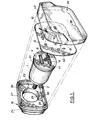
- Figure 1 shows an odometer associated with a device for maintaining a dial according to the invention.
- the counter is placed in a conventional housing 1, of cylindrical shape, provided at one of its ends with a connector 2 allowing its connection to the drive device, and at its other end with a closure plate 4.
- the plate 4 is pierced with a light 6 revealing the numbers of the kilometer counter and is crossed by a rod 8 for driving a needle 10 of speedometer.
- the needle 10 is intended to move on a dial 12 bearing the speed indication and pierced with a light 16 corresponding to the light 6 of the housing, as well as a central hole 14 allowing the passage of the rod 8.
- the dial 12 shown in Figure 1 has a substantially rectangular shape and a dimension significantly greater than that of the circular plate 4 which closes the housing 1.
- This dial is mounted on the housing by means of an adapter 18 pierced with a hole central 20 whose diameter is very slightly greater than that of the housing 1, so that the adapter 18 can freely slide on this housing.
- the diameter of the hole 20 is, however, less than that of a flange 21 carried by the housing 1, near the plate 4.
- the adapter has, in the axial direction, a substantially L-shaped cross section, one of the branches of which is constituted by the bottom 22 which is pierced with the hole 20, while its other branch is formed by a flange 24 which projects axially from the bottom 22 and has at its free end assembly means by interlocking.
- the assembly means consist of an end portion of U-shaped section, which delimits a groove 26 between two edges, respectively 27 and 28.
- the internal edge 28 has exactly the same dimension and the same shape as the edge of the dial 12, so that it can be applied exactly to it, leaving the groove 26 free.
- the device for holding the dial also includes a bezel 30 made of transparent material and comprising a flat plate 32 provided with a flange 34 from which a rib 36 leaves allowing the bezel to be assembled on the adapter 18 by fitting this rib 36 in groove 26 (fig. 2).
- the rib 36 On either side of the rib 36 are formed two shoulders 37 and 38 offset in height relative to the free end of this rib, the internal shoulder 38 being closer to the plate 32 than the external shoulder 37.
- the difference in depth of the two shoulders corresponds substantially to the thickness of the dial 12 to be maintained and the shape of the shoulder 38 corresponds to the outline of this dial, so that the dial applied to the edge 28 is housed in the shoulder 38 when the bezel 30 is tightened on the adapter 18 and when they fit together.
- the edge 28 preferably has a notch 29 while the edge 34 of the bezel 30 forms a cleat 39 which fits into the notch 29 as well as in a similar notch provided on the edge of the dial 12.
- the bezel 30 is completed at its upper part by a visor 40 which projects outwards and extends over part of the two curved lateral sides of this bezel, so as to protect the planar surface 32 thereof and to facilitate reading the dial.
- the dial can easily be placed on the meter or disassembled to be replaced.
- the adapter 18 is threaded onto the housing 1 until the bottom 22 abuts against the flange 21 of this housing.
- the height of the flange 24 is greater than that of the flange 21, so that the assembly elements protrude beyond the housing.
- the dial 12 is then placed on the edge 28 while being centered relative to this edge, by means of the rod 8 passing through the central hole 14 and optionally by means of lugs 41 carried by the plate 4 and passing through holes 42 of the screen.
- the bezel 30 is then fitted onto the adapter 18 and blocks the dial _ 12 as well as the flange 21 between it and this adapter.
- the device for holding the dial is immobilized relative to the housing 1, of which it is made completely integral.
- the indications carried by the dial are easily legible through the bezel 30.
- the device can be dismantled at any time by separating the telescope and the adapter, which makes it possible to replace it with another device, or possibly simply to maintain it.
- the adapter shown in Figure 1 has a bottom 22 which is full, but it is obvious that the bottom 22 can, if necessary, be hollowed out. It can for example be produced, as shown in FIGS. 4 and 5, by a U-shaped section element 44, the internal branch 45 of which surrounds the hole 20 for passage of the housing 1 while its outer branch 46 carries the flange 24 provided with the interlocking groove 26.
- the two branches 45 and 46 of the U are preferably connected together by a number of radial arms 47 which provide sufficient resistance to the adapter .
- the crown 45 formed by the branch of the U 44 which delimits the hole 20 can, for example, be substantially tangent to the flange 24, as the shows Figure 5, only the two side parts then being hollowed out.
- the dial, the collar and the bezel have a trapezoidal shape, such as that of the adapter shown in FIG. 6.
- Such an adapter in fact comprises, on either side of the crown 45 or of the hole 20, a rectilinear upper edge 50 and a curved lower edge 51, which are connected by smaller sides, and a bottom which can be solid or hollow like that of FIG. 5.
- the adapter can also have a circular or even triangular shape, as shown in Figures 8 and 7 respectively. It can also have any other shape, depending on the size desired for the dial, as well as the space available at the point of use.
- the telescope has a corresponding shape and preferably includes a visor similar to the visor 40 in FIGS. 2 and 3.
- the telescope may however include, as shown in FIG. 9, an inclined plate 52 provided with a rim 54, which is wide at its upper part and short at 56 at its lower part, this rim comprising assembly means on the adapter.
- the wide upper edge, 54 plays the role of the visor while the plate 52 allows reading the dial.
- the assembly means may be those which have been described, that is to say be constituted by a rib between two shoulders, or on the contrary be constituted, as shown in FIG. 9, by a peripheral rib 58 surrounding a shoulder internal 60.
- the adapter is itself provided with an interlocking rib against the shoulder 60, between two shoulders, and consequently has a shape similar to that of the rim 34 of the telescope.
- Figure 2
- Such an adapter fits onto the bezel while holding the dial between them, in the same way as the adapters and glasses of the embodiments described above, so that in this case also the dial is securely held on the housing but can be disassembled whenever desired.
- the telescope shown in Figure 9. can have any desired shape, rectangular, trapezoidal, circular, triangular, or other, and thus be suitable for various uses.
- the device of the invention therefore makes it possible to assemble on meter boxes of standard types all having an analogous shape and having as small a footprint as possible, dials of various shapes which can be large enough to allow easy reading and at the same time have a shape that matches the available location.
Landscapes
- Physics & Mathematics (AREA)
- General Physics & Mathematics (AREA)
- Measurement Of Distances Traversed On The Ground (AREA)
- Details Of Measuring And Other Instruments (AREA)
Abstract
Description
- kilométriques ou autres destinés aux véhicules à deux roues, ou analogues, est leur faible encombrement. Les efforts effectués dans ce sens ont actuellement permis effectivement de donner au mécanisme de comptage, et par suite au boîtier qui le contient, un volume réduit. Malheureusement le cadran de lecture qui recouvre généralement l'une des extrémités du boîtier a lui aussi une dimension réduite et, dans de nombreux cas, cela rend sa lecture difficile.
- Les constructeurs sont donc amenés à réaliser des boîtiers de différents formats et de dimensions variables pour les adapter à chacune de leurs applications, et notamment aux divers types de véhicules, et tenter de concilier dans chaque cas la nécessité d'éviter un trop grand encombrement avec l'exigence de lecture facile du cadran.
- La présente invention a pour but de réduire considérablement et même de supprimer ce problème en permettant de monter des cadrans de diverses dimensions et formes sur un même boîtier, pratiquement standard, et ainsi de monter toujours le cadran le mieux adapté, si grand soit-il, en ne fabriquant qu'un seul type de boîtier.
- Cette invention a en effet pour objet un dispositif de maintien d'un cadran sur un boîtier de compteur kilométrique, ou analogue, bordé par une bride périphérique, qui comporte un adaptateur annulaire, de section axiale sensiblement en L, ayant un fond percé d'un orifice de passage du boîtier et une collerette périphérique,en saillie axiale sur ce fond, qui est munie de moyens d'assemblage par emboîtement, une lunette transparente,de mêmes forme et dimension en plan que la collerette de l'adaptateur,comportant des moyens d'assemblage par emboîtement coopérant avec ceux de ce dernier et un épaulement interne d'appui du cadran à maintenir sur le pourtour de l'un de ces organes, de sorte que le cadran est bloqué entre eux lorsqu'ils sont assemblés.
- L'adaptateur peut facilement être enfilé sur un boîtier de compteur, ou analogue, et appliqué contre la bride de ce boîtier par l'assemblage de la lunette, le cadran étant serré entre eux. La forme du cadran ne dépend plus que de celle de la collerette de l'adaptateur et de la lunette et peut, par suite varier sans qu'aucune modification du boîtier ne soit nécessaire.
- De la même manière la dimension du cadran n'est nullement liée à celle du boîtier. Le cadran peut d'ailleurs être remplacé, si désiré, le dispositif étant démontable.
- Les moyens d'assemblage sont de préférence constitués par une rainure périphérique ménagée dans le bord de l'un des organes et une nervure correspondante formée sur le bord de l'autre organe, entre deux épaulements dont l'un forme l'appui du cadran, les deux épaulements étant décalés en hauteur par rapport au sommet de la nervure.
- La lunette est de préférence munie d'une visière à sa partie supérieure.
- La description ci-dessous de modes de réalisation donnés à titre d'exemples non limitatifs, et représentés aux dessins annexés, fera mieux comprendre les avantages et caractéristiques de l'invention.
- Sur ces dessins :
- - la fig. 1 est une vue éclatée d'un compteur et du dispositif de maintien du cadran;
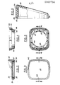
- - la fig. 2 est une vue en coupe d'une lunette, suivant la ligne 2-2 de la figure 3;
- - la fig. 3 est une vue en plan de dessus de la lunette de la figure 2;
- - les fig. 4 et 5 représentent l'adaptateur, respectivement en coupe suivant la ligne 4-4 de la figure 5, et en vue de dessus;
- - les fig. 6, 7 et 8 sont des vues de dessus de trois variantes de réalisation de l'adaptateur;
- - la fig. 9 est une vue de côté avec arrachement partiel d'une variante de réalisation de la lunette.
- La figure 1 montre un compteur kilométrique associé à un dispositif de maintien d'un cadran selon l'invention. Le compteur est placé dans un boîtier 1 classique, de forme cylindrique, muni à l'une de ses extrémités d'un raccord 2 permettant sa liaison au dispositif d'entraînement, et à son autre extrémité d'une plaque de fermeture 4. La plaque 4 est percée d'une lumière 6 laissant apparaître les chiffres du compteur de kilomètres et est traversée par une tige 8 d'entraînement d'une aiguille 10 d'indicateur de vitesse.
- L'aiguille 10 est destinée à se déplacer sur un cadran12 portant l'indication des vitesses et percé d'une lumière 16 correspondant à la lumière 6 du boîtier, ainsi que d'un trou central 14 permettant le passage de la tige 8.
- Le cadran 12 représenté sur la figure 1 a une forme sensiblement rectangulaire et une dimension nettement supérieure à celle de la plaque circulaire 4 qui ferme le boîtier 1. Ce cadran est monté sur le boîtier au moyen d'un adaptateur 18 percé d'un trou central 20 dont le diamètre est très légèrement supérieur à celui du boîtier 1, de sorte que l'adaptateur 18 peut librement coulisser sur ce boîtier. Le diamètre du trou 20 est toutefois inférieur à celui d'une bride 21 que porte le boîtier 1, à proximité de la plaque 4.
- L'adaptateur a, en direction axiale, une section droite sensiblement en forme de L dont l'une des branches est constituée par le fond 22 qui est percé du trou 20, tandis que son autre branche est formée par une collerette 24 qui fait saillie axialement à partir du fond 22 et comporte à son extrémité libre des moyens d'assemblage par emboîtement. Dans le mode de réalisation représenté les moyens d'assemblage sont constitués par une portion extrême de section en U, qui délimite une rainure 26 entre deux bords, respectivement 27 et 28. Le bord interne 28 a exactement la même dimension et la même forme que le bord du cadran 12, de sorte que celui-ci peut s'appliquer exactement sur lui en laissant libre la rainure 26.
- Le dispositif de maintien du cadran comporte également une lunette 30 réalisée en matériau transparent et comportant une plaque plane 32 munie d'un rebord 34 d'où part une nervure 36 permettant l'assemblage de la lunette sur l'adaptateur 18 par emboîtement de cette nervure 36 dans la rainure 26 (fig. 2).
- De part et d'autre de la nervure 36 sont formés deux épaulements 37 et 38 décalés en hauteur par rapport à l'extrémité libre de cette nervure, l'épaulement interne 38 étant plus proche de la plaque 32 que l'épaulement externe 37. La différence de profondeur des deux épaulements correspond sensiblement à l'épaisseur du cadran 12 à maintenir et la forme de l'épaulement 38 correspond au contour de ce cadran, de sorte que le cadran appliqué sur le bord 28 se loge dans l'épaulement 38 lors du serrage de la lunette 30 sur l'adaptateur 18 et de leur emboîtement.
- Pour faciliter cet assemblage, le bord 28 comporte de préférence une encoche 29 tandis que le bord 34 de la lunette 30 forme un taquet 39 qui vient s'emboîter dans l'encoche 29 ainsi d'ailleurs que dans une encoche analogue prévue sur le bord du cadran 12.
- La lunette 30 est complétée à sa partie supérieure par une visière 40 qui fait saillie vers l'extérieur et se prolonge sur une partie des deux côtés latéraux incurvés de cette lunette, de façon à protéger la surface plane 32 de celle-ci et à faciliter la lecture du cadran.
- Il est clair que le cadran peut facilement être mis en place sur le compteur ou démonté pour être remplacé. Lors du montage, l'adaptateur 18 est enfilé sur le boîtier 1 jusqu'au moment où son fond 22 vient buter contre la bride 21 de ce boîtier. La hauteur de la collerette 24 est supérieure à celle de la bride 21, de sorte que les éléments d'assemblage font saillie au-delà du boîtier.Le cadran 12 est alors placé sur le bord 28 en étant centré par rapport à ce bord, au moyen de la tige 8 traversant le trou central 14 et éventuellement au moyen d'ergots 41 portés par la plaque 4 et traversant des trous 42 de l'écran. La lunette 30 est alors emboîtée sur l'adaptateur 18 et bloque le cadran_12 ainsi que la bride 21 entre elle et cet adaptateur.
- Dans cette position le dispositif de maintien du cadran est immobilisé par rapport au boîtier 1 dont il est rendu complètement solidaire. Les indications portées par le cadran sont facilement lisibles à travers la lunette 30.
- Bien entendu le dispositif peut à tout moment être démonté en séparant la lunette et l'adaptateur, ce qui permet de le remplacer par un autre dispositif, ou éventuellement simplement de l'entretenir.
- L'adaptateur représenté sur la figure 1 comporte un fond 22 qui est plein, mais il est bien évident que le fond 22 peut, si nécessaire, être évidé. Il peut par exemple être réalisé, comme le montrent les figures 4 et 5, par un élément de section en U 44, dont la branche interne 45 entoure le trou 20 de passage du boîtier 1 tandis que sa branche externe 46 porte la collerette 24 munie de la rainure d'emboîtement 26. Les deux branches 45 et 46 du U sont de préférence reliées entre elles par un certain nombre de bras radiaux 47 qui assurent une résistance suffisante à l'adaptateur.
- Lorsque le cadran doit avoir une forme sensiblement rectangulaire, comme celle représentée sur les figures 1 et 5, la couronne 45 formée par la branche du U 44 qui délimite le trou 20 peut, par exemple, être sensiblement tangente à la collerette 24, comme le montre la figure 5, seules les deux parties latérales étant alors évidées.
- Il en est de même lorsque le cadran, la collerette et la lunette ont une forme trapézoïdale, telle que celle de l'adaptateur représenté sur la figure 6. Un tel adaptateur comporte en effet, de part et d'autre de la couronne 45 ou du trou 20, un bord supérieur 50 rectiligne et un bord inférieur 51 incurvé, qui sont reliés par des côtés de plus faible dimension, et un fond qui peut être plein ou évidé comme celui de la figure 5.
- L'adaptateur peut également avoir une forme circulaire ou même triangulaire, comme le montrent respectivement les figures 8 et 7. Il peut également avoir toute autre forme, selon la dimension désirée pour le cadran, ainsi que la place disponible au point d'utilisation.
- Bien entendu la lunette a une forme correspondante et comporte de préférence une visière analogue à la visière 40 des figures 2 et 3.
- Selon une variante de réalisation, la lunette peut toutefois comporter, comme le montre la figure 9, une plaque inclinée 52 munie d'un rebord 54, qui est large à sa partie supérieure et court en 56 à sa partie inférieure, ce rebord comportant des moyens d'assemblage sur l'adaptateur. Dans ce cas le bord supérieur large, 54, joue le rôle de la visière tandis que la plaque 52 permet la lecture du cadran.
- Les moyens d'assemblage peuvent être ceux qui ont été décrits, c'est-à-dire être constitués par une nervure entre deux épaulements, ou au contraire être constitués,comme le montre la figure 9, par une nervure périphérique 58 entourant un épaulement interne 60. Dans un tel cas l'adaptateur est, lui, muni d'une nervure d'em- boitement contre l'épaulement 60, entre deux épaulements, et a par suite une forme analogue à celle du rebord 34 de la lunette de la figure 2.
- Un tel adaptateur s'emboîte sur la lunette en maintenant entre eux le cadran, de la même manière que les adaptateurs et lunettes des modes de réalisation précédemment décrits, de sorte que dans ce cas également le cadran est maintenu avec sécurité sur le boîtier mais peut être démonté chaque fois que cela est désiré.
- La lunette représentée sur la figure 9.peut avoir toute forme désirée, rectangulaire, trapézoïdale, circulaire, triangulaire, ou autre, et ainsi être adaptée à diverses utilisations.
- Le dispositif de l'invention permet donc d'assembler sur des boîtiers de compteurs de types standards ayant tous une forme analogue et présentant un encombrement aussi faible que possible, des cadrans de formes diverses qui peuvent être suffisamment grands pour permettre une lecture facile et en même temps avoir une forme qui correspond à l'emplacement disponible.
Claims (7)
Applications Claiming Priority (2)
| Application Number | Priority Date | Filing Date | Title |
|---|---|---|---|
| FR8103507 | 1981-02-23 | ||
| FR8103507A FR2500660A1 (fr) | 1981-02-23 | 1981-02-23 | Dispositif de maintien d'un cadran sur un boitier et compteur kilometrique, ou analogue, muni d'un tel dispositif |
Publications (2)
| Publication Number | Publication Date |
|---|---|
| EP0060736A1 true EP0060736A1 (fr) | 1982-09-22 |
| EP0060736B1 EP0060736B1 (fr) | 1986-05-14 |
Family
ID=9255505
Family Applications (1)
| Application Number | Title | Priority Date | Filing Date |
|---|---|---|---|
| EP82400205A Expired EP0060736B1 (fr) | 1981-02-23 | 1982-02-05 | Dispositif de maintien d'un cadran sur un boîtier d'un compteur kilométrique ou analogue |
Country Status (4)
| Country | Link |
|---|---|
| US (1) | US4459848A (fr) |
| EP (1) | EP0060736B1 (fr) |
| DE (1) | DE3271091D1 (fr) |
| FR (1) | FR2500660A1 (fr) |
Cited By (4)
| Publication number | Priority date | Publication date | Assignee | Title |
|---|---|---|---|---|
| US4646574A (en) * | 1984-04-06 | 1987-03-03 | Alexander Wiegand Gmbh & Co. | Pressure gauge housing made of synthetic material |
| US4920799A (en) * | 1988-09-22 | 1990-05-01 | International Marine Industries, Inc. | Universal casing for an instrument |
| EP0469808A1 (fr) * | 1990-07-30 | 1992-02-05 | Nippon Seiki Co. Ltd. | Instrument indicateur blindé |
| EP0500078A1 (fr) * | 1991-02-22 | 1992-08-26 | Cateye Co., Ltd. | Pièces pour véhicules à deux roues avec une fermeture extérieure étanche perfectionnée |
Families Citing this family (3)
| Publication number | Priority date | Publication date | Assignee | Title |
|---|---|---|---|---|
| US4552018A (en) * | 1981-02-13 | 1985-11-12 | Square D Company | Interchangeable scale meter case |
| US4753112A (en) * | 1987-03-09 | 1988-06-28 | Dresser Industries, Inc. | Case assembly for gauge |
| GB2320093B (en) | 1996-12-04 | 2001-06-27 | Federal Ind Ind Group Inc | A pump totalizer system |
Citations (4)
| Publication number | Priority date | Publication date | Assignee | Title |
|---|---|---|---|---|
| US3543586A (en) * | 1968-11-19 | 1970-12-01 | Ametek Inc | Instrument assembly |
| US3717118A (en) * | 1970-11-27 | 1973-02-20 | Gen Electric | Indicating instrument with interchangeable face assembly |
| US3972239A (en) * | 1972-09-20 | 1976-08-03 | Robertshaw Controls Company | Gage construction and parts therefor or the like |
| FR2449270A3 (fr) * | 1979-02-08 | 1980-09-12 | Cgs Apparecch | Boitier pour instruments de mesure a echelle interchangeable en particulier pour instruments de mesure electriques a cadran |
Family Cites Families (6)
| Publication number | Priority date | Publication date | Assignee | Title |
|---|---|---|---|---|
| US1761953A (en) * | 1928-02-15 | 1930-06-03 | Ac Spark Plug Co | Instrument casing |
| US2285658A (en) * | 1940-01-10 | 1942-06-09 | Westinghouse Electric & Mfg Co | Instrument cover |
| US3712138A (en) * | 1971-02-19 | 1973-01-23 | C Alinari | Depth gauges |
| GB1452316A (en) * | 1973-11-26 | 1976-10-13 | Weir Electrical Instr Co Ltd | Electrical measuring equipment method |
| DE2742111A1 (de) * | 1977-09-19 | 1979-03-29 | Vdo Schindling | Anzeigeinstrument, insbesondere fuer fahrzeuge |
| GB2449270B (en) * | 2007-05-16 | 2011-08-31 | Peter Clarke | An electric plug removal aid |
-
1981
- 1981-02-23 FR FR8103507A patent/FR2500660A1/fr active Granted
-
1982
- 1982-02-05 EP EP82400205A patent/EP0060736B1/fr not_active Expired
- 1982-02-05 DE DE8282400205T patent/DE3271091D1/de not_active Expired
- 1982-02-11 US US06/347,990 patent/US4459848A/en not_active Expired - Fee Related
Patent Citations (4)
| Publication number | Priority date | Publication date | Assignee | Title |
|---|---|---|---|---|
| US3543586A (en) * | 1968-11-19 | 1970-12-01 | Ametek Inc | Instrument assembly |
| US3717118A (en) * | 1970-11-27 | 1973-02-20 | Gen Electric | Indicating instrument with interchangeable face assembly |
| US3972239A (en) * | 1972-09-20 | 1976-08-03 | Robertshaw Controls Company | Gage construction and parts therefor or the like |
| FR2449270A3 (fr) * | 1979-02-08 | 1980-09-12 | Cgs Apparecch | Boitier pour instruments de mesure a echelle interchangeable en particulier pour instruments de mesure electriques a cadran |
Cited By (6)
| Publication number | Priority date | Publication date | Assignee | Title |
|---|---|---|---|---|
| US4646574A (en) * | 1984-04-06 | 1987-03-03 | Alexander Wiegand Gmbh & Co. | Pressure gauge housing made of synthetic material |
| US4920799A (en) * | 1988-09-22 | 1990-05-01 | International Marine Industries, Inc. | Universal casing for an instrument |
| EP0469808A1 (fr) * | 1990-07-30 | 1992-02-05 | Nippon Seiki Co. Ltd. | Instrument indicateur blindé |
| US5239259A (en) * | 1990-07-30 | 1993-08-24 | Nippon Seiki Co., Ltd. | Moving magnet type indicating instrument combined with a counter mechanism |
| EP0500078A1 (fr) * | 1991-02-22 | 1992-08-26 | Cateye Co., Ltd. | Pièces pour véhicules à deux roues avec une fermeture extérieure étanche perfectionnée |
| AU650095B2 (en) * | 1991-02-22 | 1994-06-09 | Cateye Co., Ltd. | A meter for a two wheeled vehicle |
Also Published As
| Publication number | Publication date |
|---|---|
| EP0060736B1 (fr) | 1986-05-14 |
| FR2500660B1 (fr) | 1985-03-22 |
| US4459848A (en) | 1984-07-17 |
| FR2500660A1 (fr) | 1982-08-27 |
| DE3271091D1 (en) | 1986-06-19 |
Similar Documents
| Publication | Publication Date | Title |
|---|---|---|
| FR2917589A1 (fr) | Moulin reglable a moudre les condiments en grains | |
| FR3071296A1 (fr) | Dispositif d'etancheite pour organe de dialogue homme-machine | |
| FR2463436A1 (fr) | Montre a elements de forme profilee, notamment non circulaire | |
| EP0036818B1 (fr) | Dispositif porte-accessoires pour objectifs d'appareils de prises de vues photographiques et pare-soleil utilisable avec ce dispositif | |
| EP0060736B1 (fr) | Dispositif de maintien d'un cadran sur un boîtier d'un compteur kilométrique ou analogue | |
| EP0823979A1 (fr) | Boite de montre munie d'une lunette tournante | |
| EP0919813B1 (fr) | Dispositif de protection d'un codeur magnétique | |
| EP3180657B1 (fr) | Boite de montre munie d'un element d'habillage | |
| FR2551172A1 (fr) | Valve de degazage pour boitier etanche | |
| FR2661498A1 (fr) | Perfectionnements aux dispositifs de mesure de niveau de carburant dans un vehicule automobile. | |
| EP0334182B1 (fr) | Boîte de montre munie d'une coiffe | |
| EP0060156B1 (fr) | Compteur pour véhicule à deux roues, ou analogue | |
| EP1241541B1 (fr) | Boîte de montre assemblée par la lunette | |
| EP0564768B1 (fr) | Sous-ensemble pour le rappel élastique de l'organe de retenue d'un élément de fixation alpine | |
| EP0269872A1 (fr) | Boîte de montre | |
| FR2672346A1 (fr) | Vis pour dispositif antivol et dispositif antivol. | |
| EP3526563B1 (fr) | Boitier avec un capteur pyroelectrique | |
| FR3036674A1 (fr) | Groupe motoreducteur comprenant une membrane respirante | |
| WO1994027422A2 (fr) | Garniture pour clef | |
| CH404210A (fr) | Dispositif d'enroulement d'un ruban souple pour mesures linéaires | |
| CH442771A (fr) | Boîtier fermé | |
| FR2606985A1 (fr) | Dispositif de suspension notamment de boitiers de cassettes video | |
| FR2746181A1 (fr) | Compteur de fluide comprenant un totalisateur maintenu par un organe elastique | |
| CH647885A5 (fr) | Dispositif de reperage du deroulement de la bande magnetique d'une cassette et cassette munie d'un tel dispositif. | |
| FR2576849A1 (fr) | Roulette |
Legal Events
| Date | Code | Title | Description |
|---|---|---|---|
| PUAI | Public reference made under article 153(3) epc to a published international application that has entered the european phase |
Free format text: ORIGINAL CODE: 0009012 |
|
| AK | Designated contracting states |
Designated state(s): BE DE GB IT LU NL |
|
| 17P | Request for examination filed |
Effective date: 19830219 |
|
| GRAA | (expected) grant |
Free format text: ORIGINAL CODE: 0009210 |
|
| ITF | It: translation for a ep patent filed | ||
| AK | Designated contracting states |
Kind code of ref document: B1 Designated state(s): BE DE GB IT LU NL |
|
| REF | Corresponds to: |
Ref document number: 3271091 Country of ref document: DE Date of ref document: 19860619 |
|
| PLBE | No opposition filed within time limit |
Free format text: ORIGINAL CODE: 0009261 |
|
| STAA | Information on the status of an ep patent application or granted ep patent |
Free format text: STATUS: NO OPPOSITION FILED WITHIN TIME LIMIT |
|
| 26N | No opposition filed | ||
| PGFP | Annual fee paid to national office [announced via postgrant information from national office to epo] |
Ref country code: DE Payment date: 19900125 Year of fee payment: 9 |
|
| PGFP | Annual fee paid to national office [announced via postgrant information from national office to epo] |
Ref country code: GB Payment date: 19900131 Year of fee payment: 9 |
|
| ITTA | It: last paid annual fee | ||
| PGFP | Annual fee paid to national office [announced via postgrant information from national office to epo] |
Ref country code: NL Payment date: 19900228 Year of fee payment: 9 |
|
| PGFP | Annual fee paid to national office [announced via postgrant information from national office to epo] |
Ref country code: BE Payment date: 19900313 Year of fee payment: 9 |
|
| PG25 | Lapsed in a contracting state [announced via postgrant information from national office to epo] |
Ref country code: GB Effective date: 19910205 |
|
| PG25 | Lapsed in a contracting state [announced via postgrant information from national office to epo] |
Ref country code: BE Effective date: 19910228 |
|
| PGFP | Annual fee paid to national office [announced via postgrant information from national office to epo] |
Ref country code: LU Payment date: 19910228 Year of fee payment: 10 |
|
| PG25 | Lapsed in a contracting state [announced via postgrant information from national office to epo] |
Ref country code: NL Effective date: 19910901 |
|
| GBPC | Gb: european patent ceased through non-payment of renewal fee | ||
| NLV4 | Nl: lapsed or anulled due to non-payment of the annual fee | ||
| PG25 | Lapsed in a contracting state [announced via postgrant information from national office to epo] |
Ref country code: DE Effective date: 19911101 |
|
| PG25 | Lapsed in a contracting state [announced via postgrant information from national office to epo] |
Ref country code: LU Free format text: LAPSE BECAUSE OF NON-PAYMENT OF DUE FEES Effective date: 19920205 |