EP0060737A1 - Bras de lève-vitre, notamment pour véhicule automobile - Google Patents
Bras de lève-vitre, notamment pour véhicule automobile Download PDFInfo
- Publication number
- EP0060737A1 EP0060737A1 EP82400278A EP82400278A EP0060737A1 EP 0060737 A1 EP0060737 A1 EP 0060737A1 EP 82400278 A EP82400278 A EP 82400278A EP 82400278 A EP82400278 A EP 82400278A EP 0060737 A1 EP0060737 A1 EP 0060737A1
- Authority
- EP
- European Patent Office
- Prior art keywords
- roller
- base
- link
- window
- arm according
- Prior art date
- Legal status (The legal status is an assumption and is not a legal conclusion. Google has not performed a legal analysis and makes no representation as to the accuracy of the status listed.)
- Granted
Links
- 238000002788 crimping Methods 0.000 claims description 5
- 210000000078 claw Anatomy 0.000 claims description 3
- 230000000295 complement effect Effects 0.000 claims description 3
- 239000002184 metal Substances 0.000 abstract description 2
- 239000000463 material Substances 0.000 description 3
- 239000007787 solid Substances 0.000 description 2
- DHKHKXVYLBGOIT-UHFFFAOYSA-N 1,1-Diethoxyethane Chemical compound CCOC(C)OCC DHKHKXVYLBGOIT-UHFFFAOYSA-N 0.000 description 1
- 239000011354 acetal resin Substances 0.000 description 1
- 238000000034 method Methods 0.000 description 1
- 230000000149 penetrating effect Effects 0.000 description 1
- 229920006324 polyoxymethylene Polymers 0.000 description 1
- 238000005096 rolling process Methods 0.000 description 1
Images
Classifications
-
- E—FIXED CONSTRUCTIONS
- E05—LOCKS; KEYS; WINDOW OR DOOR FITTINGS; SAFES
- E05F—DEVICES FOR MOVING WINGS INTO OPEN OR CLOSED POSITION; CHECKS FOR WINGS; WING FITTINGS NOT OTHERWISE PROVIDED FOR, CONCERNED WITH THE FUNCTIONING OF THE WING
- E05F11/00—Man-operated mechanisms for operating wings, including those which also operate the fastening
- E05F11/38—Man-operated mechanisms for operating wings, including those which also operate the fastening for sliding windows, e.g. vehicle windows, to be opened or closed by vertical movement
- E05F11/44—Man-operated mechanisms for operating wings, including those which also operate the fastening for sliding windows, e.g. vehicle windows, to be opened or closed by vertical movement operated by one or more lifting arms
- E05F11/445—Man-operated mechanisms for operating wings, including those which also operate the fastening for sliding windows, e.g. vehicle windows, to be opened or closed by vertical movement operated by one or more lifting arms for vehicle windows
-
- E—FIXED CONSTRUCTIONS
- E05—LOCKS; KEYS; WINDOW OR DOOR FITTINGS; SAFES
- E05Y—INDEXING SCHEME ASSOCIATED WITH SUBCLASSES E05D AND E05F, RELATING TO CONSTRUCTION ELEMENTS, ELECTRIC CONTROL, POWER SUPPLY, POWER SIGNAL OR TRANSMISSION, USER INTERFACES, MOUNTING OR COUPLING, DETAILS, ACCESSORIES, AUXILIARY OPERATIONS NOT OTHERWISE PROVIDED FOR, APPLICATION THEREOF
- E05Y2800/00—Details, accessories and auxiliary operations not otherwise provided for
- E05Y2800/26—Form or shape
-
- E—FIXED CONSTRUCTIONS
- E05—LOCKS; KEYS; WINDOW OR DOOR FITTINGS; SAFES
- E05Y—INDEXING SCHEME ASSOCIATED WITH SUBCLASSES E05D AND E05F, RELATING TO CONSTRUCTION ELEMENTS, ELECTRIC CONTROL, POWER SUPPLY, POWER SIGNAL OR TRANSMISSION, USER INTERFACES, MOUNTING OR COUPLING, DETAILS, ACCESSORIES, AUXILIARY OPERATIONS NOT OTHERWISE PROVIDED FOR, APPLICATION THEREOF
- E05Y2900/00—Application of doors, windows, wings or fittings thereof
- E05Y2900/50—Application of doors, windows, wings or fittings thereof for vehicles
- E05Y2900/53—Type of wing
- E05Y2900/55—Windows
-
- Y—GENERAL TAGGING OF NEW TECHNOLOGICAL DEVELOPMENTS; GENERAL TAGGING OF CROSS-SECTIONAL TECHNOLOGIES SPANNING OVER SEVERAL SECTIONS OF THE IPC; TECHNICAL SUBJECTS COVERED BY FORMER USPC CROSS-REFERENCE ART COLLECTIONS [XRACs] AND DIGESTS
- Y10—TECHNICAL SUBJECTS COVERED BY FORMER USPC
- Y10T—TECHNICAL SUBJECTS COVERED BY FORMER US CLASSIFICATION
- Y10T403/00—Joints and connections
- Y10T403/49—Member deformed in situ
-
- Y—GENERAL TAGGING OF NEW TECHNOLOGICAL DEVELOPMENTS; GENERAL TAGGING OF CROSS-SECTIONAL TECHNOLOGIES SPANNING OVER SEVERAL SECTIONS OF THE IPC; TECHNICAL SUBJECTS COVERED BY FORMER USPC CROSS-REFERENCE ART COLLECTIONS [XRACs] AND DIGESTS
- Y10—TECHNICAL SUBJECTS COVERED BY FORMER USPC
- Y10T—TECHNICAL SUBJECTS COVERED BY FORMER US CLASSIFICATION
- Y10T74/00—Machine element or mechanism
- Y10T74/20—Control lever and linkage systems
- Y10T74/20576—Elements
- Y10T74/20582—Levers
-
- Y—GENERAL TAGGING OF NEW TECHNOLOGICAL DEVELOPMENTS; GENERAL TAGGING OF CROSS-SECTIONAL TECHNOLOGIES SPANNING OVER SEVERAL SECTIONS OF THE IPC; TECHNICAL SUBJECTS COVERED BY FORMER USPC CROSS-REFERENCE ART COLLECTIONS [XRACs] AND DIGESTS
- Y10—TECHNICAL SUBJECTS COVERED BY FORMER USPC
- Y10T—TECHNICAL SUBJECTS COVERED BY FORMER US CLASSIFICATION
- Y10T74/00—Machine element or mechanism
- Y10T74/20—Control lever and linkage systems
- Y10T74/20576—Elements
- Y10T74/20732—Handles
- Y10T74/20744—Hand crank
Definitions
- the present invention relates to window regulator arms, in particular for motor vehicles, of the type comprising a link which carries a roller at one end.
- This roller is intended to cooperate with a groove of complementary shape provided either in the bottom of the window, or in a guide slide of the latter.
- the relatively large thickness (of the order of 25 to 30/10 mm) of the sheets usually used to make the rods of the window regulator arms makes it necessary to mount the roller on the rod by a riveting operation. This prohibits the use of a plastic material to constitute the axis of the roller, because the connection by riveting would not be sufficiently solid.
- the invention aims to provide an arrangement taking advantage of this reduction in thickness to lighten the arm and reduce the cost.
- the invention relates to a window-lift arm of the aforementioned type, in which the roller consists of a body swiveling on an axis, characterized in that the axis of the roller has a flat base on which the corresponding end of the link is crimped.
- connection method is sufficiently solid even when the axis of the roller is made of plastic.
- the invention also relates to a window regulator arm of the type indicated above, characterized in that the roller is fixed to the rod by crimping the corresponding end thereof on a open base secured to the body of the roller, the roller and its base preferably forming a single piece of plastic.
- the base has a stud received in a hole complementary to the end of the link. Indeed, we can then be content to use to crimp the base of the claws or a protruding rim on the periphery of the end of the link (which does not weaken this end), because the stud prevents any tilting of the roller towards the outside of the link.
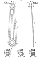
- the window lift arm shown in Figs. 1 and 2 is made up of two parts, namely a rod 1 made of thin sheet metal 12 to 15 / 10mm thick and a one-piece roller 2 made of plastic, for example made of acetal resin, fixed to this rod .
- the link 1 symmetrical with respect to a longitudinal axis X-X, has a large circular end 3 and a small circular end 4 joined by a body 5 whose edges forming the tangents common to the two ends 3 and 4.
- the end 3 has a grooved central hole 6 for fixing it to a driving shaft (not shown) or, by means of a grooved shaft section, to another similar link (not shown).
- the end 4 is pierced with a circular central hole 7, and on its periphery project several radial tabs 8.
- the body 5 and the end 3 are provided with an appropriate stiffening rib.
- the roller 2 (FIGS. 2 and 3) comprises a roller body 9 whose meridian profile in diabolo is conjugated with that of a groove provided in a bottom window or in a guide rail (not shown) in which this body is intended to move.
- This body 9 is extended at one end by a base 10 molded which has a roughly conical shape and a flat end face 11 of circular shape and of diameter roughly equal to that of the end 4 of the rod 1.
- On this face 11 projects a central stud 12 of the same diameter as the hole 7 of the rod and surrounded by a circular groove 13 which gives a certain elasticity to the base 10. From the end face 14 of the roller opposite the face 11 shares a blind recess 15 for lightening.
- roller 2 and the connecting rod 1 To assemble the roller 2 and the connecting rod 1, it suffices to apply the face 11 of the roller on the end 4 of the connecting rod, the stud 12 penetrating into the hole 7 for centering, then to fold down all the legs 8 by above the base 10 for carrying out a crimping thereof.
- the assembly is very rigid despite the flexibility of the plastic material constituting the roller 2.
- Fig. 4 shows a roller 2A which does not differ from the roller 2 in FIG. 3 only by the meridian profile of its body 9A. Indeed, this profile is roughly spherical and ends on the side opposite to the base 10 by an annular lip 15 which is defined by a circular groove 16 provided in the end face 14.
- roller 2A moves in a conjugate groove, and the lip 15 catches play and plays an anti-noise role.
- the base 10 is one end of an axis 17 made of plastic material on which the journal 9B of the roller 2B, also made of plastic, pivots (or, according to a variant not shown, ball joint).
- axis 17 made of plastic material on which the journal 9B of the roller 2B, also made of plastic, pivots (or, according to a variant not shown, ball joint).
- mounting the arm is then more complicated, since there is one more piece, and the cost of the complete arm is higher.
- the claws 8 of the link can be replaced by a circular rim folded down by rolling on the conical face of the base 10.
Landscapes
- Window Of Vehicle (AREA)
Abstract
Description
- La présente invention est relative aux bras de lève-vitre, notamment pour véhicules automobiles,du type comprenant une biellette qui porte à une extrémité un galet . Ce galet est destiné à coopérer avec une rainure de forme complémentaire prévue soit dans le bas de vitre, soit dans une glissière de guidage de ce dernier.
- L'épaisseur relativement forte (de l'ordre de 25 à 30/10 mm) des tôles utilisées habituellement pour réalisersles biellettes des bras de lève-vitre rend nécessaire le montage du galet sur la biellette par une opération de rivetage. Ceci interdit d'utiliser une matière plastique pour constituer l'axe du galet, car la liaison par rivetage ne serait pas suffisamment solide.
- Des efforts récents effectués en vue d'alléger les lève-vitre ont conduit à l'adoption de tôles beaucoup plus minces, de l'ordre de 12 à 15/10 de mm, pour constituer les biellettes.
- L'invention a pour but de fournir un agencement mettant à profit cette diminution d'épaisseur pour alléger le bras et en réduire le coût.
- A cet effet, suivant un premier mode de réalisation, l'invention a pour objet un bras de lève-vitre du type précité, dans lequel le galet est constitué d'un corps tourillonnant sur un axe, caractérisé en ce que l'axe du galet comporte une embase épanouie sur laquelle est sertie l'extrémité correspondante de la biellette.
- En effet, ce mode de liaison est suffisamment solide même lorsque l'axe du galet est en matière plastique.
- Suivant un deuxième mode de réalisation, l'invention a également pour objet un bras de lève-vitre du type indiqué plus haut, caractérisé en ce que le galet est fixé à la biellette par sertissage de l'extrémité correspondante de celle-ci sur une embase épanouie solidaire du corps du galet, le galet et son embase formant de préférence une pièce unique en matière plastique.
- Dans un mode de réalisation avantageux, l'embase présente un téton reçu dans un trou complémentaire de l'extrémité de la biellette. En effet, on peut alors se contenter d'utiliser pour sertir l'embase des griffes ou un rebord en saillie sur la périphérie de l'extrémité de la biellette (ce qui n'affaiblit pas cette extrémité), car le téton empêche tout basculement du galet vers l'extérieur de la biellette.
- L'invention est exposée cï-après plus en détail à l'aide du dessin annexé, qui en représente seulement deux modes d'exécution. Sur ces dessins :
- la Fig. 1 est une vue de face d'un bras de lève-vitre suivant l'invention;
- la Fig. 2 est une vue de côté de ce bras;
- la Fig. 3 est une vue en coupe axiale du galet de ce bras;
- les Fig . 4 et 5 sont des vues analogues à la Fig. 3 de deux variantes de galets.
- Le bras de lève-vitre représenté aux Fig . 1 et 2 est constitué de deux pièces, à savoir d'une biellette 1 en tôle mince de 12 à 15/10mm d'épaisseur et d'un galet monobloc 2 en matière plastique, par exemple en une résine acétal, fixé sur cette biellette.
- La biellette 1, symétrique par rapport à un axe longitudinal X-X, comporte une grande extrémité circulaire 3 et une petite extrémité circulaire 4 réunies par un corps 5 dont les bords formant les tangentes communes aux deux extrémités 3 et 4.
- L'extrémité 3 présente un trou central cannelé 6 pour sa fixation sur un arbre moteur (non représenté) ou, par l'intermédiaire d'un tronçon d'arbre cannelé, sur une autre biellette analogue (non représentée). L'extrémité 4 est percée d'un trou central circulaire 7, et sur sa périphérie font saillie plusieurs pattes radiales 8. Le corps 5 et l'extrémité 3 sont pourvus d'un nervurage approprié de rigidification.
- Le galet 2 (Fig . 2 et 3) comprend un corps de galet 9 dont le profil méridien en diabolo est conjugué de celui d'une rainure prévue dans un bas de vitre ou dans une glissière de guidage (non représentés) dans lequel ce corps est destiné à se déplacer. Ce corps 9 est prolongé à une extrémité par une embase 10 venue de moulage qui présente une forme à peu près conique et une face d'extrémité plane 11 de forme circulaire et de diamètre à peu près égal à celui de l'extrémité 4 de la biellette 1. Sur cette face 11 fait saillie un téton central 12 de même diamètre que le trou 7 de la biellette et entouré d'une gorge circulaire 13 qui confère une certaine élasticité à l'embase 10. De la face d'extrémité 14 du galet opposée à la face 11 part un évidement borgne 15 d'allègement.
- Pour assembler le galet 2 et la biellette 1, il suffit d'appliquer la face 11 du galet sur l'extrémité 4 de la biellette, le téton 12 pénétrant dans le trou 7 pour réaliser le centrage, puis de rabattre toutes les pattes 8 par-dessus l'embase 10 pour réaliser un sertissage de celle-ci. L'assemblage est très rigide malgré la souplesse de la matière plastique constituant le galet 2.
- La Fig. 4 montre un galet 2A qui ne diffère du galet 2 de la Fig. 3 que par le profil méridien de son corps 9A. En effet, ce profil est à peu près sphérique et se termine du côté opposé à l'embase 10 par une lèvre annulaire 15 qui est définie par une rainure circulaire 16 prévue dans la face d'extrémité 14.
- En service, le galet 2A se déplace dans une rainure conjuguée, et la lèvre 15 rattrape les jeux et joue un rôle antibruit.
- Dans le mode de réalisation de la Fig. 5, l'embase 10 est une extrémité d'un axe 17 en matière plastique sur lequel tourillonne (ou,suivant une variante non représentée,rotule) le corps 9B du galet 2B, également en matière plastique. Cependant, le montage du bras est alors plus compliqué, puisqu'il y a une pièce de plus, et le coût du bras complet est plus élevé.
- Dans chaque cas, les griffes 8 de la biellette peuvent être remplacées par un rebord circulaire rabattu par roulage sur la face conique de l'embase 10.
Claims (10)
Applications Claiming Priority (2)
| Application Number | Priority Date | Filing Date | Title |
|---|---|---|---|
| FR8105180 | 1981-03-16 | ||
| FR8105180A FR2501770A1 (fr) | 1981-03-16 | 1981-03-16 | Bras de leve-vitre, notamment pour vehicule automobile |
Publications (2)
| Publication Number | Publication Date |
|---|---|
| EP0060737A1 true EP0060737A1 (fr) | 1982-09-22 |
| EP0060737B1 EP0060737B1 (fr) | 1985-05-22 |
Family
ID=9256269
Family Applications (1)
| Application Number | Title | Priority Date | Filing Date |
|---|---|---|---|
| EP82400278A Expired EP0060737B1 (fr) | 1981-03-16 | 1982-02-17 | Bras de lève-vitre, notamment pour véhicule automobile |
Country Status (9)
| Country | Link |
|---|---|
| US (1) | US4458553A (fr) |
| EP (1) | EP0060737B1 (fr) |
| JP (1) | JPS57161284A (fr) |
| BR (1) | BR8201372A (fr) |
| CA (1) | CA1201143A (fr) |
| DE (1) | DE3263599D1 (fr) |
| ES (1) | ES263544Y (fr) |
| FR (1) | FR2501770A1 (fr) |
| MX (1) | MX154824A (fr) |
Cited By (1)
| Publication number | Priority date | Publication date | Assignee | Title |
|---|---|---|---|---|
| FR2561298A1 (fr) * | 1984-03-16 | 1985-09-20 | Reitter & Schefenacker Kg | Leve-vitre perfectionne pour vehicules automobiles |
Families Citing this family (2)
| Publication number | Priority date | Publication date | Assignee | Title |
|---|---|---|---|---|
| JP6425582B2 (ja) * | 2015-02-27 | 2018-11-21 | シロキ工業株式会社 | ウインドレギュレータ |
| RU2705563C1 (ru) * | 2019-02-26 | 2019-11-08 | Акционерное общество "Научно-производственное предприятие "Исток" имени А.И. Шокина" (АО "НПП "Исток" им. Шокина") | Баночное окно ввода-вывода энергии свч |
Citations (2)
| Publication number | Priority date | Publication date | Assignee | Title |
|---|---|---|---|---|
| FR2002561A1 (fr) * | 1968-02-24 | 1969-10-17 | Wilmot Breeden Ltd | |
| FR2123650A5 (fr) * | 1971-01-26 | 1972-09-15 | Citroen Sa |
Family Cites Families (11)
| Publication number | Priority date | Publication date | Assignee | Title |
|---|---|---|---|---|
| US2899832A (en) * | 1959-08-18 | Window regulator drive mechanism | ||
| US1278441A (en) * | 1917-05-28 | 1918-09-10 | Fred G Meyer | Spark-intensifier. |
| US1667031A (en) * | 1921-07-20 | 1928-04-24 | Dura Co | Roller for window-control mechanism |
| US1736703A (en) * | 1926-05-26 | 1929-11-19 | Ternstedt Mfg Co | Window-regulator connection |
| US1753700A (en) * | 1927-02-21 | 1930-04-08 | Dura Co | Handle structure |
| US2903909A (en) * | 1955-06-14 | 1959-09-15 | Engel Wolfgang | Pitmans or links for sewing machine transmissions |
| DE1056950B (de) * | 1956-11-24 | 1959-05-06 | Avog Elektro Und Feinmechanik | Lagerbuechse aus elastischem Werkstoff fuer Scheibenwischerantriebe |
| US3130443A (en) * | 1962-03-20 | 1964-04-28 | Radio Steel & Mfg Co | Coaster wagon handle |
| US3466803A (en) * | 1968-05-28 | 1969-09-16 | Gen Motors Corp | Guide arrangement |
| JPS5939212Y2 (ja) * | 1976-06-10 | 1984-11-01 | アイシン精機株式会社 | 自動車におけるフアンカツプリング用駆動軸 |
| DE2852415B2 (de) * | 1978-12-04 | 1981-04-30 | Süddeutsche Kühlerfabrik Julius Fr. Behr GmbH & Co KG, 7000 Stuttgart | Klemmverbindung |
-
1981
- 1981-03-16 FR FR8105180A patent/FR2501770A1/fr active Granted
-
1982
- 1982-02-17 DE DE8282400278T patent/DE3263599D1/de not_active Expired
- 1982-02-17 EP EP82400278A patent/EP0060737B1/fr not_active Expired
- 1982-03-01 ES ES1982263544U patent/ES263544Y/es not_active Expired
- 1982-03-08 US US06/355,959 patent/US4458553A/en not_active Expired - Fee Related
- 1982-03-10 CA CA000397985A patent/CA1201143A/fr not_active Expired
- 1982-03-10 MX MX191734A patent/MX154824A/es unknown
- 1982-03-12 JP JP57039272A patent/JPS57161284A/ja active Pending
- 1982-03-15 BR BR8201372A patent/BR8201372A/pt unknown
Patent Citations (2)
| Publication number | Priority date | Publication date | Assignee | Title |
|---|---|---|---|---|
| FR2002561A1 (fr) * | 1968-02-24 | 1969-10-17 | Wilmot Breeden Ltd | |
| FR2123650A5 (fr) * | 1971-01-26 | 1972-09-15 | Citroen Sa |
Cited By (1)
| Publication number | Priority date | Publication date | Assignee | Title |
|---|---|---|---|---|
| FR2561298A1 (fr) * | 1984-03-16 | 1985-09-20 | Reitter & Schefenacker Kg | Leve-vitre perfectionne pour vehicules automobiles |
Also Published As
| Publication number | Publication date |
|---|---|
| ES263544U (es) | 1982-11-01 |
| ES263544Y (es) | 1983-04-16 |
| JPS57161284A (en) | 1982-10-04 |
| EP0060737B1 (fr) | 1985-05-22 |
| US4458553A (en) | 1984-07-10 |
| FR2501770A1 (fr) | 1982-09-17 |
| CA1201143A (fr) | 1986-02-25 |
| FR2501770B1 (fr) | 1984-04-13 |
| BR8201372A (pt) | 1983-01-25 |
| MX154824A (es) | 1987-12-15 |
| DE3263599D1 (en) | 1985-06-27 |
Similar Documents
| Publication | Publication Date | Title |
|---|---|---|
| EP1613516B1 (fr) | Procede et agencement pour l'assemblage d'un dispositif d'essuie-glace sur un vehicule automobile | |
| EP0448446B1 (fr) | Articulation continue sans satellite à rattrapage de jeu | |
| EP0462855B1 (fr) | Dispositif de retenue d'un arbre logé dans un fourreau et son application aux directions d'automobile | |
| FR2706380A1 (fr) | Articulation à rattrapage de jeux utilisée dans les sièges automobiles. | |
| FR2551706A1 (fr) | Appui-tete pour un vehicule automobile | |
| FR3080808A1 (fr) | Procédé d’assemblage d’un élément de transmission destiné à un dispositif de réglage de la hauteur du siège | |
| EP4594112A1 (fr) | Enjoliveur pour une roue en tole a positionement peripherique ameliore | |
| FR2630272A1 (fr) | Element de retenue pour palier de moteur electrique et son procede de montage | |
| EP1199243A1 (fr) | Système et volant de direction pour véhicule | |
| EP0060737B1 (fr) | Bras de lève-vitre, notamment pour véhicule automobile | |
| FR3039617A1 (fr) | Boitier de transmission et module de transmission equipe d'un tel boitier | |
| EP0601937B1 (fr) | Dispositif réglable de montage d'un pare-chocs sur une structure de véhicule automobile | |
| FR2692854A1 (fr) | Manette pour commutateur électrique, notamment pour véhicule automobile. | |
| FR2554066A1 (fr) | Systeme de construction de retroviseurs de vehicules | |
| EP0649774B1 (fr) | Dispositif pour immobiliser en rotation et sans jeu une vis de réglage d'un réflecteur de projecteur | |
| FR2491402A1 (fr) | Pare-soleil, notamment pour vehicule automobile | |
| EP0018294A1 (fr) | Support pour un bras rabattable de rétroviseur extérieur | |
| EP1438771B1 (fr) | Contacteur electrique tournant et ensemble de direction de vehicule automobile muni de ce contacteur | |
| EP0068960B1 (fr) | Assemblage d'articulations pour sièges de véhicule | |
| FR2550147A2 (fr) | Tete d'assemblage matricee d'un element d'essuie-glace, son procede de fabrication et element d'essuie-glace la comportant | |
| EP1067037B1 (fr) | Mécanisme de direction à crémaillère pour véhicule automobile | |
| EP4114693B1 (fr) | Support de boite a rotule, bielle et procede d'assemblage correspondants | |
| FR2690959A1 (fr) | Friction d'embrayage, notamment pour véhicule automobile. | |
| EP0672573A1 (fr) | Ensemble de colonne de direction réglable en position notamment pour véhicule automobile | |
| FR2495066A1 (fr) | Dispositif d'articulation de pare-soleil |
Legal Events
| Date | Code | Title | Description |
|---|---|---|---|
| PUAI | Public reference made under article 153(3) epc to a published international application that has entered the european phase |
Free format text: ORIGINAL CODE: 0009012 |
|
| AK | Designated contracting states |
Designated state(s): DE GB IT SE |
|
| 17P | Request for examination filed |
Effective date: 19820811 |
|
| ITF | It: translation for a ep patent filed | ||
| GRAA | (expected) grant |
Free format text: ORIGINAL CODE: 0009210 |
|
| AK | Designated contracting states |
Designated state(s): DE GB IT SE |
|
| REF | Corresponds to: |
Ref document number: 3263599 Country of ref document: DE Date of ref document: 19850627 |
|
| PLBE | No opposition filed within time limit |
Free format text: ORIGINAL CODE: 0009261 |
|
| STAA | Information on the status of an ep patent application or granted ep patent |
Free format text: STATUS: NO OPPOSITION FILED WITHIN TIME LIMIT |
|
| 26N | No opposition filed | ||
| PGFP | Annual fee paid to national office [announced via postgrant information from national office to epo] |
Ref country code: DE Payment date: 19890102 Year of fee payment: 8 |
|
| PGFP | Annual fee paid to national office [announced via postgrant information from national office to epo] |
Ref country code: SE Payment date: 19890227 Year of fee payment: 8 |
|
| ITTA | It: last paid annual fee | ||
| PGFP | Annual fee paid to national office [announced via postgrant information from national office to epo] |
Ref country code: GB Payment date: 19890228 Year of fee payment: 8 |
|
| PG25 | Lapsed in a contracting state [announced via postgrant information from national office to epo] |
Ref country code: GB Effective date: 19900217 |
|
| PG25 | Lapsed in a contracting state [announced via postgrant information from national office to epo] |
Ref country code: SE Effective date: 19900218 |
|
| GBPC | Gb: european patent ceased through non-payment of renewal fee | ||
| PG25 | Lapsed in a contracting state [announced via postgrant information from national office to epo] |
Ref country code: DE Effective date: 19901101 |
|
| EUG | Se: european patent has lapsed |
Ref document number: 82400278.6 Effective date: 19901107 |