EP0060827A1 - Dispositif de refroidissement pour le trépan d'une haveuse - Google Patents
Dispositif de refroidissement pour le trépan d'une haveuse Download PDFInfo
- Publication number
- EP0060827A1 EP0060827A1 EP82890023A EP82890023A EP0060827A1 EP 0060827 A1 EP0060827 A1 EP 0060827A1 EP 82890023 A EP82890023 A EP 82890023A EP 82890023 A EP82890023 A EP 82890023A EP 0060827 A1 EP0060827 A1 EP 0060827A1
- Authority
- EP
- European Patent Office
- Prior art keywords
- chisel
- valve
- shut
- shaft
- coupling element
- Prior art date
- Legal status (The legal status is an assumption and is not a legal conclusion. Google has not performed a legal analysis and makes no representation as to the accuracy of the status listed.)
- Granted
Links
- 238000005520 cutting process Methods 0.000 title claims abstract description 24
- 238000001816 cooling Methods 0.000 title claims abstract description 4
- 239000003245 coal Substances 0.000 title 1
- 230000008878 coupling Effects 0.000 claims abstract description 15
- 238000010168 coupling process Methods 0.000 claims abstract description 15
- 238000005859 coupling reaction Methods 0.000 claims abstract description 15
- 239000000498 cooling water Substances 0.000 claims abstract description 14
- XLYOFNOQVPJJNP-UHFFFAOYSA-N water Substances O XLYOFNOQVPJJNP-UHFFFAOYSA-N 0.000 claims abstract description 12
- 238000007789 sealing Methods 0.000 claims description 4
- 239000000356 contaminant Substances 0.000 description 3
- 238000005507 spraying Methods 0.000 description 3
- 239000000428 dust Substances 0.000 description 2
- 238000005553 drilling Methods 0.000 description 1
- 238000011010 flushing procedure Methods 0.000 description 1
- 238000003754 machining Methods 0.000 description 1
- 239000011435 rock Substances 0.000 description 1
Images
Classifications
-
- E—FIXED CONSTRUCTIONS
- E21—EARTH OR ROCK DRILLING; MINING
- E21C—MINING OR QUARRYING
- E21C35/00—Details of, or accessories for, machines for slitting or completely freeing the mineral from the seam, not provided for in groups E21C25/00 - E21C33/00, E21C37/00 or E21C39/00
- E21C35/18—Mining picks; Holders therefor
- E21C35/187—Mining picks; Holders therefor with arrangement of fluid-spraying nozzles
Definitions
- the invention relates to a device for cooling the chisel of a cutting machine with a nozzle arranged in the area of the chisel for the cooling water to be sprayed under pressure, to which the water supply can be shut off by a shut-off valve, the chisel on the chisel holder against the force of a spring and the hydraulic pressure of the cooling water axially ver limited by the average pressure - is mounted slidably and the stop valve is coupled with the bit by a coupling member such that it opens at a sliding movement of the bit in direction of the cutting pressure.
- a device enables the spraying of the cooling water from the nozzle to be restricted to the period during which the chisel in question attacks the rock.
- the spraying of the cooling water is interrupted during the period in which the chisel in question is not in operation and therefore a considerable saving in cooling water is made possible.
- This not only has the advantage of saving water, but above all also the advantage that the sole is not excessively softened by water spraying out.
- the chisel shaft is displaceably mounted in the chisel holder against a spring force and engages with a collar on the coupling element which actuates the shut-off valve.
- This coupling element must be arranged on the outside of the chisel holder and is therefore exposed to damage during cutting operation.
- the invention now aims to design the actuation of the shut-off valve so that it is reliable and secured against damage.
- the invention consists essentially in the fact that the chisel is cap-shaped in a manner known per se and encloses a chisel shank that can be inserted into the chisel holder, that the cap-shaped chisel is mounted axially displaceably on the shank is and that the shut-off valve and the coupling element is arranged in the chisel shaft.
- Cap-shaped chisels which overlap the chisel shaft immovably inserted in the chisel holder and are rotatably arranged thereon are known.
- the arrangement is such that the shut-off valve closes counter to the direction of the cutting pressure and that the chisel shaft has a central bore in which a plunger acting on the movable valve body and possibly integrally formed therewith is axially displaceable, which forms the coupling element.
- the movable valve body is expediently formed by a valve cone, but can also be formed by a ball.
- this movable valve body it is also possible to design this movable valve body as a slide, which is moved into the open position by the coupling element when the cutting pressure occurs in a slide mirror.
- the design is expediently such that the movable valve body opens in the direction of the cutting pressure and the spring which loads the chisel against the cutting pressure is formed by the spring acting on the movable valve body.
- a spring is sufficient, which both holds the valve in the closed position and loads the chisel against the cutting pressure.
- the valve housing is preferably tubular and inserted in a central bore of the chisel shank. This enables a simple design of the chisel shank, the machining of the chisel shank being restricted to simple turning and drilling work.
- the cap-shaped chisel should be rotatably mounted on the chisel shaft and it is essential that the chisel can actually twist during operation and is not blocked by dust and contaminants entering the gap between the chisel shaft and the chisel, since in this case the cutting accuracy of the chisel in Question would be asked. This inevitably results in a certain, albeit small, gap between the inner wall of the cap-shaped chisel and the chisel shaft, and there is a risk that dust and other contaminants which hinder the rotary movement of the chisel will accumulate in this gap.
- the plunger is expediently leaky in the bore of the chisel shaft and in a guide bore of the valve housing.
- This enables water to escape from the valve along the tappet to the annular gap between the chisel and the chisel shaft, and this annular gap is thereby rinsed, so that contaminants which have penetrated into this annular gap are discharged to the outside.
- This ensures the easy rotation of the chisel on the chisel shaft.
- a slotted ring in particular a sealing ring, is inserted between the tappet and the guide bore of the valve housing for this purpose, the slot of which forms a passage cross section for water. By dimensioning this slot, the water outlet can be limited to the minimum required for flushing the annular gap.
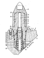
- the invention is illustrated using an exemplary embodiment which shows an axial section through the chisel and the chisel shank and through the chisel holder shows.
- the surface of the chisel holder 1 is welded to the cutting head 2.
- a chisel shank 3 is inserted into the chisel holder 1 and is screwed in by means of a thread 4.
- 5 is a seal.
- a cap-shaped chisel 6 is rotatably mounted on the chisel shaft 3.
- the annular groove 7 has a greater axial extent than the inserted circlip, so that the chisel 6 is axially displaceably mounted on the chisel shaft.
- a plunger 10 is guided axially displaceably, which consists of one piece with a valve cone 11.
- the valve cone 11 is pressed onto the valve seat 13 by a spring 12.
- This spring also loads the plunger 6 in the direction opposite to the cutting pressure via the plunger 10, so that in the idle state the chisel 6 is lifted from a shoulder 14 of the chisel shaft by a dimension a.
- the valve 11 is lifted from the seat against the force of the spring 12 and the chisel 6 sits on the shoulder 14.
- the cooling water passes through bores 17 into an annular space 18 and from here through bores 19 of a tubular valve housing 20 into the space 21 of the valve housing 20.
- 22 is an annular filter, which extends around the valve housing 20 in the region of the bores 19 is laid around.
- a sealing ring 32 is inserted into a groove 31 in the plunger 10.
- This sealing ring which consists for example of hard plastic, is slotted on its circumference, so that a small amount of water can pass out of the space 23.
- the plunger 10 is guided in the bore 9 of the chisel shank 3 so that a slight amount of water can pass into the space 33 between the chisel shank 3 and the chisel 6 via the gap in the seal 32.
- This water can escape through the annular gap 34 between the chisel shaft 3 and the chisel 6 at 35, so that this annular gap 34 is rinsed.
- valve housing 20 is screwed into the chisel shaft 3.
Landscapes
- Engineering & Computer Science (AREA)
- Mining & Mineral Resources (AREA)
- Geology (AREA)
- Life Sciences & Earth Sciences (AREA)
- General Life Sciences & Earth Sciences (AREA)
- Geochemistry & Mineralogy (AREA)
- Mechanical Engineering (AREA)
- Lift Valve (AREA)
- Drilling And Exploitation, And Mining Machines And Methods (AREA)
- Auxiliary Devices For Machine Tools (AREA)
- Earth Drilling (AREA)
- Sampling And Sample Adjustment (AREA)
- Sawing (AREA)
- Drilling And Boring (AREA)
- Percussive Tools And Related Accessories (AREA)
Applications Claiming Priority (2)
| Application Number | Priority Date | Filing Date | Title |
|---|---|---|---|
| AT0113581A AT369859B (de) | 1981-03-12 | 1981-03-12 | Einrichtung zum kuehlen der meissel einer schraemmaschine |
| AT1135/81 | 1981-03-12 |
Publications (2)
| Publication Number | Publication Date |
|---|---|
| EP0060827A1 true EP0060827A1 (fr) | 1982-09-22 |
| EP0060827B1 EP0060827B1 (fr) | 1984-05-09 |
Family
ID=3507354
Family Applications (1)
| Application Number | Title | Priority Date | Filing Date |
|---|---|---|---|
| EP82890023A Expired EP0060827B1 (fr) | 1981-03-12 | 1982-02-16 | Dispositif de refroidissement pour le trépan d'une haveuse |
Country Status (16)
| Country | Link |
|---|---|
| US (1) | US4456306A (fr) |
| EP (1) | EP0060827B1 (fr) |
| JP (1) | JPS57163040A (fr) |
| AT (1) | AT369859B (fr) |
| AU (1) | AU547795B2 (fr) |
| BR (1) | BR8201281A (fr) |
| CA (1) | CA1176665A (fr) |
| DE (1) | DE3260140D1 (fr) |
| ES (1) | ES509902A0 (fr) |
| IN (1) | IN155702B (fr) |
| MX (1) | MX6604E (fr) |
| PL (1) | PL138252B1 (fr) |
| RO (1) | RO84541B (fr) |
| SU (1) | SU1269743A3 (fr) |
| YU (1) | YU40082A (fr) |
| ZA (1) | ZA821221B (fr) |
Cited By (14)
| Publication number | Priority date | Publication date | Assignee | Title |
|---|---|---|---|---|
| GB2127459A (en) * | 1982-09-22 | 1984-04-11 | Bergwerksverband Gmbh | Mining machines |
| EP0067144B1 (fr) * | 1981-06-04 | 1984-07-25 | VOEST-ALPINE Aktiengesellschaft | Dispositif de refroidissement pour les outils d'une haveuse |
| EP0067145B1 (fr) * | 1981-06-04 | 1984-07-25 | VOEST-ALPINE Aktiengesellschaft | Dispositif de refroidissement pour les outils d'une haveuse |
| GB2135715A (en) * | 1983-03-02 | 1984-09-05 | Padley & Venables Ltd | Water sprayed, mineral mining pick assembly |
| US4488759A (en) * | 1982-03-10 | 1984-12-18 | Santrade Ltd. | Device for supplying fluid to a tool for breaking hard material |
| US4542942A (en) * | 1982-07-06 | 1985-09-24 | Voest-Alpine Aktiengesellschaft | Bit holder equipped with a spraying device |
| EP0111143A3 (en) * | 1982-11-13 | 1985-11-21 | Voest-Alpine Aktiengesellschaft | Core bit with damped guided cylindrical shank |
| FR2571427A1 (fr) * | 1984-10-06 | 1986-04-11 | Boart Hwf Gmbh & Co Kg | Outil de havage, en particulier pour des machines pour tracages en veine |
| EP0125232B1 (fr) * | 1983-04-11 | 1986-11-26 | VOEST-ALPINE Aktiengesellschaft | Procédé pour l'abattage des roches et dispositif pour la mise en oeuvre de ce procédé |
| EP0229238A1 (fr) * | 1985-12-13 | 1987-07-22 | Boart International Limited | Outil d'abattage pour l'abattage de minéraux, en particulier de charbon |
| US4976496A (en) * | 1988-07-19 | 1990-12-11 | Sandvik Ab | Valve openable in response to displacement of a cutting tool |
| AT227U1 (de) * | 1990-04-05 | 1995-05-26 | Voest Alpine Bergtechnik | Schneezaun |
| CN101555792B (zh) * | 2009-05-23 | 2011-07-20 | 山东卡特重工有限公司 | 一种可内喷雾的掘进机的闸板式喷嘴 |
| CN117359318A (zh) * | 2023-11-28 | 2024-01-09 | 中铜(昆明)铜业有限公司 | 铜材钻孔装置及方法 |
Families Citing this family (12)
| Publication number | Priority date | Publication date | Assignee | Title |
|---|---|---|---|---|
| US4664450A (en) * | 1983-03-02 | 1987-05-12 | Padley & Venables Limited | Holder for a pick, and the combination of a pick and holder |
| US4569558A (en) * | 1983-07-25 | 1986-02-11 | The Regents Of The University Of California | Drag bit construction |
| AT381364B (de) * | 1984-10-24 | 1986-10-10 | Voest Alpine Ag | Einrichtung zur zufuehrung von wasser unter druck zu austrittsduesen am umfang eines schraemwerkzeuges |
| SE452495B (sv) * | 1985-06-13 | 1987-11-30 | Sandvik Ab | Anordning for vetsketillforsel till ett verktyg for brytning av fasta material |
| US4765686A (en) * | 1987-10-01 | 1988-08-23 | Gte Valenite Corporation | Rotatable cutting bit for a mining machine |
| AT389738B (de) * | 1988-04-28 | 1990-01-25 | Voest Alpine Ag | Vorrichtung zum intermittierenden bespruehen von meisseln eines schraemkopfes |
| GB0017470D0 (en) * | 2000-07-18 | 2000-08-30 | Hydra Tools Int Plc | Pick box for housing a mineral cutter pick |
| RU2183745C2 (ru) * | 2000-09-18 | 2002-06-20 | Открытое акционерное общество "Копейский машиностроительный завод" | Исполнительный орган горной машины |
| DE10261646B4 (de) * | 2002-12-27 | 2010-02-25 | Wirtgen Gmbh | Schrämwerkzeug |
| US7234782B2 (en) * | 2005-02-18 | 2007-06-26 | Sandvik Intellectual Property Ab | Tool holder block and sleeve retained therein by interference fit |
| US8215719B2 (en) * | 2009-10-06 | 2012-07-10 | Kennametal Inc. | Rotatable cutting tool with through coolant |
| CN118342015B (zh) * | 2024-06-11 | 2024-10-01 | 爱博特新能源科技江苏有限公司 | 一种led灯具外壳加工机床 |
Citations (4)
| Publication number | Priority date | Publication date | Assignee | Title |
|---|---|---|---|---|
| DE1283777B (de) * | 1967-11-22 | 1968-11-28 | Austin Hoy And Company Ltd Sta | Auswechselbare Schraemmeissel mit Meisselhalter und mit Zufuehrungen fuer Fluessigkeit |
| DE1998508U (de) * | 1968-05-22 | 1968-12-19 | Heinz Hoetten | Vorrichtung zur berieselung von foerderwagen |
| EP0010534A1 (fr) * | 1978-10-19 | 1980-04-30 | VOEST-ALPINE Aktiengesellschaft | Dispositif de refroidissement des burins des outils de coupe pour des machines d'abattage et du front de taille et d'empêchement de la formation de poussière |
| DE2854307A1 (de) * | 1978-12-15 | 1980-07-03 | Kennametal Inc | Halter zur anbringung von meisseln, insbesondere von rundschaftmeisseln an bergbaulichen gewinnungs- und streckenvortriebsmaschinen |
Family Cites Families (1)
| Publication number | Priority date | Publication date | Assignee | Title |
|---|---|---|---|---|
| SU685821A1 (ru) * | 1978-06-29 | 1979-09-15 | Копейский Ордена Трудового Красного Знамени Машиностроительный Завод Им. С.М.Кирова | Режуща коронка горного комбайна |
-
1981
- 1981-03-12 AT AT0113581A patent/AT369859B/de not_active IP Right Cessation
-
1982
- 1982-02-16 EP EP82890023A patent/EP0060827B1/fr not_active Expired
- 1982-02-16 DE DE8282890023T patent/DE3260140D1/de not_active Expired
- 1982-02-20 IN IN199/CAL/82A patent/IN155702B/en unknown
- 1982-02-23 AU AU80728/82A patent/AU547795B2/en not_active Ceased
- 1982-02-23 CA CA000396819A patent/CA1176665A/fr not_active Expired
- 1982-02-23 YU YU00400/82A patent/YU40082A/xx unknown
- 1982-02-24 ZA ZA821221A patent/ZA821221B/xx unknown
- 1982-02-25 ES ES509902A patent/ES509902A0/es active Granted
- 1982-02-25 SU SU823416190A patent/SU1269743A3/ru active
- 1982-03-02 US US06/353,936 patent/US4456306A/en not_active Expired - Fee Related
- 1982-03-09 PL PL1982235364A patent/PL138252B1/pl unknown
- 1982-03-10 BR BR8201281A patent/BR8201281A/pt unknown
- 1982-03-11 JP JP57038838A patent/JPS57163040A/ja active Granted
- 1982-03-11 RO RO106876A patent/RO84541B/ro unknown
- 1982-03-12 MX MX82101016U patent/MX6604E/es unknown
Patent Citations (4)
| Publication number | Priority date | Publication date | Assignee | Title |
|---|---|---|---|---|
| DE1283777B (de) * | 1967-11-22 | 1968-11-28 | Austin Hoy And Company Ltd Sta | Auswechselbare Schraemmeissel mit Meisselhalter und mit Zufuehrungen fuer Fluessigkeit |
| DE1998508U (de) * | 1968-05-22 | 1968-12-19 | Heinz Hoetten | Vorrichtung zur berieselung von foerderwagen |
| EP0010534A1 (fr) * | 1978-10-19 | 1980-04-30 | VOEST-ALPINE Aktiengesellschaft | Dispositif de refroidissement des burins des outils de coupe pour des machines d'abattage et du front de taille et d'empêchement de la formation de poussière |
| DE2854307A1 (de) * | 1978-12-15 | 1980-07-03 | Kennametal Inc | Halter zur anbringung von meisseln, insbesondere von rundschaftmeisseln an bergbaulichen gewinnungs- und streckenvortriebsmaschinen |
Cited By (17)
| Publication number | Priority date | Publication date | Assignee | Title |
|---|---|---|---|---|
| EP0067145B1 (fr) * | 1981-06-04 | 1984-07-25 | VOEST-ALPINE Aktiengesellschaft | Dispositif de refroidissement pour les outils d'une haveuse |
| EP0067144B1 (fr) * | 1981-06-04 | 1984-07-25 | VOEST-ALPINE Aktiengesellschaft | Dispositif de refroidissement pour les outils d'une haveuse |
| AT388210B (de) * | 1982-03-10 | 1989-05-26 | Santrade Ltd | Vorrichtung zum zufuehren von fliessmittel zu einem werkzeug zum brechen von hartem material |
| US4488759A (en) * | 1982-03-10 | 1984-12-18 | Santrade Ltd. | Device for supplying fluid to a tool for breaking hard material |
| US4542942A (en) * | 1982-07-06 | 1985-09-24 | Voest-Alpine Aktiengesellschaft | Bit holder equipped with a spraying device |
| GB2127459A (en) * | 1982-09-22 | 1984-04-11 | Bergwerksverband Gmbh | Mining machines |
| US4534597A (en) * | 1982-09-22 | 1985-08-13 | Bergwerksverband Gmbh | Mining tool with automatic sprinkler control |
| EP0111143A3 (en) * | 1982-11-13 | 1985-11-21 | Voest-Alpine Aktiengesellschaft | Core bit with damped guided cylindrical shank |
| EP0160757A1 (fr) * | 1983-03-02 | 1985-11-13 | G-D M & C Limited | Support de pic et dispositif composé de support et de pic |
| GB2135715A (en) * | 1983-03-02 | 1984-09-05 | Padley & Venables Ltd | Water sprayed, mineral mining pick assembly |
| EP0125232B1 (fr) * | 1983-04-11 | 1986-11-26 | VOEST-ALPINE Aktiengesellschaft | Procédé pour l'abattage des roches et dispositif pour la mise en oeuvre de ce procédé |
| FR2571427A1 (fr) * | 1984-10-06 | 1986-04-11 | Boart Hwf Gmbh & Co Kg | Outil de havage, en particulier pour des machines pour tracages en veine |
| EP0229238A1 (fr) * | 1985-12-13 | 1987-07-22 | Boart International Limited | Outil d'abattage pour l'abattage de minéraux, en particulier de charbon |
| US4976496A (en) * | 1988-07-19 | 1990-12-11 | Sandvik Ab | Valve openable in response to displacement of a cutting tool |
| AT227U1 (de) * | 1990-04-05 | 1995-05-26 | Voest Alpine Bergtechnik | Schneezaun |
| CN101555792B (zh) * | 2009-05-23 | 2011-07-20 | 山东卡特重工有限公司 | 一种可内喷雾的掘进机的闸板式喷嘴 |
| CN117359318A (zh) * | 2023-11-28 | 2024-01-09 | 中铜(昆明)铜业有限公司 | 铜材钻孔装置及方法 |
Also Published As
| Publication number | Publication date |
|---|---|
| MX6604E (es) | 1985-08-14 |
| ZA821221B (en) | 1983-01-26 |
| AT369859B (de) | 1983-02-10 |
| IN155702B (fr) | 1985-02-23 |
| RO84541A (fr) | 1984-06-21 |
| CA1176665A (fr) | 1984-10-23 |
| DE3260140D1 (en) | 1984-06-14 |
| EP0060827B1 (fr) | 1984-05-09 |
| PL235364A1 (fr) | 1982-09-27 |
| AU547795B2 (en) | 1985-11-07 |
| YU40082A (en) | 1986-02-28 |
| ATA113581A (de) | 1982-06-15 |
| RO84541B (ro) | 1984-08-30 |
| US4456306A (en) | 1984-06-26 |
| PL138252B1 (en) | 1986-08-30 |
| JPS6257795B2 (fr) | 1987-12-02 |
| ES8302845A1 (es) | 1983-01-16 |
| ES509902A0 (es) | 1983-01-16 |
| BR8201281A (pt) | 1983-01-18 |
| SU1269743A3 (ru) | 1986-11-07 |
| AU8072882A (en) | 1982-09-16 |
| JPS57163040A (en) | 1982-10-07 |
Similar Documents
| Publication | Publication Date | Title |
|---|---|---|
| EP0060827B1 (fr) | Dispositif de refroidissement pour le trépan d'une haveuse | |
| EP0099350B1 (fr) | Porte-outil équipé d'un dispositif de projection d'eau | |
| DE3338158C2 (fr) | ||
| DE4327825C2 (de) | Drosselrückschlagelement | |
| DE3102884C2 (de) | Schrämmeißel mit Wasserbedüsung | |
| EP0067145B1 (fr) | Dispositif de refroidissement pour les outils d'une haveuse | |
| EP0067144B1 (fr) | Dispositif de refroidissement pour les outils d'une haveuse | |
| DE2506928A1 (de) | Ueberdruckventil, insbesondere gebirgsschlagventil fuer hydraulische grubenstempel | |
| DE2241378A1 (de) | Mit stroemungsmittel unter druck betaetigtes werkzeug, insbesondere schraubenzieher | |
| EP0125232A1 (fr) | Procédé pour l'abattage des roches et dispositif pour la mise en oeuvre de ce procédé | |
| DE3721802A1 (de) | Sprueheinrichtung fuer kuehlfluessigkeit aus duesen eines schraemkopfes | |
| DE3542274C2 (fr) | ||
| AT389738B (de) | Vorrichtung zum intermittierenden bespruehen von meisseln eines schraemkopfes | |
| DE2731016A1 (de) | Spritzpistole | |
| DE3544126C1 (de) | Werkzeug zum Hereingewinnen von mineralischen Rohstoffen,insbesondere von Kohle oder Hartstein | |
| DE3007055C2 (de) | Sprühdüse für eine Gewinnungsmaschine des Bergbaus | |
| DE4238055C2 (de) | Reinigungspistole zum handgesteuerten Durchlaß von Fluiden | |
| DE3301806C2 (de) | Lufthebe-Vorrichtung für Bohrrohre | |
| DE2951011A1 (de) | Duese, insbesondere fuer schraemwalzen von gewinnungsmaschinen des untertagebergbaues | |
| DE1207907B (de) | Bohrlochwerkzeug | |
| EP0837214A2 (fr) | Foreuse à percussion | |
| DE10255953B3 (de) | Vorrichtung zum Verhindern des Rückflusses von Kunstoffschmelze | |
| DE2946661C2 (de) | Sprühdüse für eine Gewinnungsmaschine des Bergbaues | |
| DE19535795C2 (de) | Prüfeinrichtung für die Funktion von Düsen einer meißelgesteuerten Schneidspurbedüsung | |
| DE3703114C2 (fr) |
Legal Events
| Date | Code | Title | Description |
|---|---|---|---|
| PUAI | Public reference made under article 153(3) epc to a published international application that has entered the european phase |
Free format text: ORIGINAL CODE: 0009012 |
|
| AK | Designated contracting states |
Designated state(s): DE FR GB |
|
| 17P | Request for examination filed |
Effective date: 19820930 |
|
| GRAA | (expected) grant |
Free format text: ORIGINAL CODE: 0009210 |
|
| AK | Designated contracting states |
Designated state(s): DE FR GB |
|
| REF | Corresponds to: |
Ref document number: 3260140 Country of ref document: DE Date of ref document: 19840614 |
|
| ET | Fr: translation filed | ||
| PGFP | Annual fee paid to national office [announced via postgrant information from national office to epo] |
Ref country code: DE Payment date: 19850222 Year of fee payment: 4 |
|
| PLBE | No opposition filed within time limit |
Free format text: ORIGINAL CODE: 0009261 |
|
| STAA | Information on the status of an ep patent application or granted ep patent |
Free format text: STATUS: NO OPPOSITION FILED WITHIN TIME LIMIT |
|
| 26N | No opposition filed | ||
| PG25 | Lapsed in a contracting state [announced via postgrant information from national office to epo] |
Ref country code: GB Effective date: 19890216 |
|
| GBPC | Gb: european patent ceased through non-payment of renewal fee | ||
| PG25 | Lapsed in a contracting state [announced via postgrant information from national office to epo] |
Ref country code: FR Free format text: LAPSE BECAUSE OF NON-PAYMENT OF DUE FEES Effective date: 19891027 |
|
| PG25 | Lapsed in a contracting state [announced via postgrant information from national office to epo] |
Ref country code: DE Effective date: 19891101 |
|
| REG | Reference to a national code |
Ref country code: FR Ref legal event code: ST |