EP0060938A2 - Dispositif pour le contrôle de la sortie d'un agent actif d'une tuyère d'un brûleur oscillant - Google Patents
Dispositif pour le contrôle de la sortie d'un agent actif d'une tuyère d'un brûleur oscillant Download PDFInfo
- Publication number
- EP0060938A2 EP0060938A2 EP81110241A EP81110241A EP0060938A2 EP 0060938 A2 EP0060938 A2 EP 0060938A2 EP 81110241 A EP81110241 A EP 81110241A EP 81110241 A EP81110241 A EP 81110241A EP 0060938 A2 EP0060938 A2 EP 0060938A2
- Authority
- EP
- European Patent Office
- Prior art keywords
- active substance
- slide
- membrane
- valve
- oscillating
- Prior art date
- Legal status (The legal status is an assumption and is not a legal conclusion. Google has not performed a legal analysis and makes no representation as to the accuracy of the status listed.)
- Granted
Links
Images

Classifications
-
- F—MECHANICAL ENGINEERING; LIGHTING; HEATING; WEAPONS; BLASTING
- F23—COMBUSTION APPARATUS; COMBUSTION PROCESSES
- F23C—METHODS OR APPARATUS FOR COMBUSTION USING FLUID FUEL OR SOLID FUEL SUSPENDED IN A CARRIER GAS OR AIR
- F23C15/00—Apparatus in which combustion takes place in pulses influenced by acoustic resonance in a gas mass
Definitions
- the invention relates to a device on a vibrating burner for controlling the exit of active substance to be atomized from an outlet nozzle opening in a vibrating burner chamber when the vibrating burner is stopped.
- the object of the invention is to provide a device of this type which automatically ensures when the oscillating burner fails or is switched off that no active substance escapes from the nozzle with certainty.
- the device is characterized by a valve arrangement which can be adjusted by the intake air flow of the oscillating burner against spring force and which, in the event of failure of the intake air flow under the spring force, generates an active ingredient sucking back suction from the nozzle in a line leading to the oscillating combustion chamber.
- a separate line can be provided with a valve that can be adjusted by hand, for example, for feeding the active substance into the oscillating combustion chamber.
- a preferred embodiment of the invention is characterized in that the line in which the suction is generated in the event of failure of the intake air flow is at the same time the line through which the active substance is introduced into the oscillating combustion chamber.
- the device is characterized in that the line via the valve arrangement is guided from an active substance storage container to an oscillating combustion chamber and is also blocked by the valve arrangement in the event of a failure of the intake air flow.
- valve is a slide valve, the slide of which can be adjusted by a membrane, the membrane bordering a space which has an air inlet opening through which the air is subjected to a pressure which depends on the strength of the air intake flow flows in, which has a first always open small outlet opening, through which air flows out, and which has a second outlet opening to be opened and closed by a manually operable actuator.
- the membrane In normal operation, the membrane is only under the pressure which arises because of the always open small outlet opening. By opening the second outlet opening by means of the manually operable actuator, this pressure is reduced and the slide valve is thereby brought into its closed position.
- the slide is coupled to a second membrane which delimits a space through which the active substance flows downstream of the slide valve. If the slide valve is moved into its closed position, the space mentioned is automatically enlarged as a result, which results in the desired return suction effect.
- the slide is preferably biased by a spring in the closed position of the slide valve.
- the effective area of the first membrane is preferably larger than that of the second membrane, so that the space mentioned for sucking back the active substance can certainly expand.
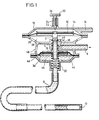
- the slide 2 of a slide valve 4 lies in a line 6, 8 leading to an oscillating combustion chamber, which is also not shown, under an active substance reservoir, not shown.
- the line 6 is connected on the input side to the active substance storage container.
- the line 8 ends in a nozzle 10 which is adjacent to the oscillating combustion chamber.
- the slide 2 is to be adjusted by a membrane 12.
- the membrane 12 borders a space 14 which has an air inlet opening 16 through which air flows in at a pressure which is dependent on the strength of the air intake flow of the oscillating burner.
- the room has a first always open small outlet opening 18, through which air flows out, and a second outlet opening 22, which can be opened and closed by a manually operable actuator 20 Knurl handle 26 is twisted.
- the opening 22 is closed, as a result of which the pressure in the space 14 rises, the membrane 12 pushes the slide 2 downward and the slide valve 4 thus comes into the open position.
- the space 28 below the membrane 12 communicates with the atmosphere via openings 30.
- a spring 32 tries to push the slide body 2 upwards against the pressure in the space 14 in order to bring the slide body 2 into the closed position.
- the slide 2 passes through a second membrane 34, to which it is attached with a flange 36.
- the slide 2 is hollow inside. Active ingredient to be flowed through the line 6 can flow through the constriction 38 and the ring distribution space 42 into the interior of the slide 2 when the openings 40 in the slide 2 are at the level of the ring distribution space 42.
- the active substance then flows through a space 44 below the membrane 34 before it reaches the line 8.
- the slide 2 reaches the closed position, it takes the membrane 34 upwards and the volume of the space 44 increases, causing active substance to flow out the line 8 is sucked back.
- the space 46 above the membrane 34 is in constant communication with the atmosphere via an opening 48.
- FIG. 2 is essentially constructed like that according to FIG. 1, so that only the different elements are to be described.
- a displaceable bolt 50 is provided which connects the two membranes 12, 34.
- the Lei leading from the active substance container into the space 46 above the membrane 34 tion 6 has been omitted.
- the line 8 opens into a line 52 which leads to the nozzle 10.
- the line 52 is connected on the input side to the active substance container via a tap.
Landscapes
- Engineering & Computer Science (AREA)
- Chemical & Material Sciences (AREA)
- Combustion & Propulsion (AREA)
- Mechanical Engineering (AREA)
- General Engineering & Computer Science (AREA)
- Pressure-Spray And Ultrasonic-Wave- Spray Burners (AREA)
- Catching Or Destruction (AREA)
- Tea And Coffee (AREA)
- Fluid-Driven Valves (AREA)
- Fluidized-Bed Combustion And Resonant Combustion (AREA)
- Nozzles (AREA)
- Feeding And Controlling Fuel (AREA)
Priority Applications (1)
| Application Number | Priority Date | Filing Date | Title |
|---|---|---|---|
| AT81110241T ATE12680T1 (de) | 1981-01-09 | 1981-12-07 | Vorrichtung zur steuerung des wirkstoffaustritts aus einer schwingbrennerduese. |
Applications Claiming Priority (2)
| Application Number | Priority Date | Filing Date | Title |
|---|---|---|---|
| DE3100414 | 1981-01-09 | ||
| DE19813100414 DE3100414A1 (de) | 1981-01-09 | 1981-01-09 | Vorrichtung an einem schwingbrenner zur steuerung des austritts von zu vernebelndem wirkstoff aus einer austrittsduese |
Publications (3)
| Publication Number | Publication Date |
|---|---|
| EP0060938A2 true EP0060938A2 (fr) | 1982-09-29 |
| EP0060938A3 EP0060938A3 (en) | 1983-03-09 |
| EP0060938B1 EP0060938B1 (fr) | 1985-04-10 |
Family
ID=6122341
Family Applications (1)
| Application Number | Title | Priority Date | Filing Date |
|---|---|---|---|
| EP81110241A Expired EP0060938B1 (fr) | 1981-01-09 | 1981-12-07 | Dispositif pour le contrôle de la sortie d'un agent actif d'une tuyère d'un brûleur oscillant |
Country Status (7)
| Country | Link |
|---|---|
| US (1) | US4504214A (fr) |
| EP (1) | EP0060938B1 (fr) |
| JP (1) | JPS57130563A (fr) |
| AT (1) | ATE12680T1 (fr) |
| BR (1) | BR8200067A (fr) |
| CA (1) | CA1195229A (fr) |
| DE (2) | DE3100414A1 (fr) |
Families Citing this family (3)
| Publication number | Priority date | Publication date | Assignee | Title |
|---|---|---|---|---|
| JPH0232993Y2 (fr) * | 1986-01-29 | 1990-09-06 | ||
| DE4236371C2 (de) * | 1992-10-28 | 1995-08-17 | Erno Raumfahrttechnik Gmbh | Vorrichtung und Verfahren zum Einspritzen |
| JP3467438B2 (ja) * | 1999-09-29 | 2003-11-17 | アドバンス電気工業株式会社 | 背圧制御弁 |
Family Cites Families (6)
| Publication number | Priority date | Publication date | Assignee | Title |
|---|---|---|---|---|
| DE666982C (de) * | 1934-12-21 | 1938-11-02 | Gustav Schlick | OElzerstaeuber mit einem den OElzufluss steuernden Regelglied |
| GB746068A (en) * | 1953-09-25 | 1956-03-07 | Urquhart S 1926 Ltd | Improvements relating to the supply of fuel to liquid fuel burners |
| AT196045B (de) * | 1955-01-14 | 1958-02-25 | Serge Ing Ziegler | Vorrichtung zur Verhütung des Nachtropfens von Öl aus der Speiseleitung von mit Drucköl betriebenen Ölbrennern |
| AT196046B (de) * | 1956-01-13 | 1958-02-25 | Serge Ing Ziegler | Vorrichtung zur Verhütung des Nachtropfens von Öl aus der Speiseleitung von mit Druckluft arbeitenden Ölbrennern |
| GB1237076A (en) * | 1967-09-21 | 1971-06-30 | Pilkington Brothers Ltd | Improvements in and relating to apparatus for controlling the supply of liquid fuel to burners |
| US3817264A (en) * | 1973-02-14 | 1974-06-18 | Precision Control Prod Corp | Valve |
-
1981
- 1981-01-09 DE DE19813100414 patent/DE3100414A1/de not_active Ceased
- 1981-12-07 AT AT81110241T patent/ATE12680T1/de active
- 1981-12-07 DE DE8181110241T patent/DE3169904D1/de not_active Expired
- 1981-12-07 EP EP81110241A patent/EP0060938B1/fr not_active Expired
- 1981-12-07 JP JP56195755A patent/JPS57130563A/ja active Granted
- 1981-12-22 CA CA000392900A patent/CA1195229A/fr not_active Expired
- 1981-12-29 US US06/335,386 patent/US4504214A/en not_active Expired - Fee Related
-
1982
- 1982-01-07 BR BR8200067A patent/BR8200067A/pt unknown
Also Published As
| Publication number | Publication date |
|---|---|
| BR8200067A (pt) | 1982-10-26 |
| JPS57130563A (en) | 1982-08-13 |
| EP0060938B1 (fr) | 1985-04-10 |
| DE3169904D1 (en) | 1985-05-15 |
| EP0060938A3 (en) | 1983-03-09 |
| CA1195229A (fr) | 1985-10-15 |
| DE3100414A1 (de) | 1982-08-12 |
| ATE12680T1 (de) | 1985-04-15 |
| JPH0125625B2 (fr) | 1989-05-18 |
| US4504214A (en) | 1985-03-12 |
Similar Documents
| Publication | Publication Date | Title |
|---|---|---|
| DE2038618C3 (de) | Handbetätigtes Druck-Atmungsgerät | |
| DE3521908C2 (fr) | ||
| DE3422066C2 (fr) | ||
| DE2737680C3 (de) | Spritzpistole | |
| DE1566580B2 (de) | Zyklussteuerung für ein Beatmungsgerät | |
| DE3445320C2 (de) | Verfahren zur Abgabe von Dampf an die Luft in einem Raum und Gerät zur Durchführung des Verfahrens | |
| EP0665321B1 (fr) | Dispositif d'injection d'eau pour fer à repasser à vapeur | |
| DE10102846A1 (de) | Aerosolgenerator | |
| DE4225928A1 (de) | Zerstäubervorrichtung mit Heizeinrichtung | |
| DE2537307B2 (de) | Beatmungsgerät | |
| DE2447426A1 (de) | Spruehvorrichtung | |
| DE2516473A1 (de) | Zahnaerztliche spritzvorrichtung | |
| EP0127573B1 (fr) | Générateur d'aérosol | |
| DE2233529C3 (de) | Entstaubungsanlage mit Filterkörpern | |
| DE2620881B2 (de) | Zerstäuberdüse | |
| DE1964907A1 (de) | Spruehgeraet,insbesondere rueckentragbares Spruehgeraet | |
| EP0060938B1 (fr) | Dispositif pour le contrôle de la sortie d'un agent actif d'une tuyère d'un brûleur oscillant | |
| DE2535716A1 (de) | Von hand betaetigbares geraet zur pneumatischen entfernung von staub oder fluessigkeiten | |
| DE1491668B1 (de) | Anaesthesiervorrichtung | |
| DE69203299T2 (de) | Vorrichtung zum spruehen von fluessigkeiten. | |
| CH453240A (de) | Auf eine Sprühdose aufsteckbare Betätigungsvorrichtung | |
| DE4221155C1 (fr) | ||
| DE3706963A1 (de) | Aus- und durchlaufvorrichtung (insbesondere sprueh und/oder spuel-vorrichtung) insbesondere mit treibgas oder pumpantrieb, fuer gase, fluessigkeiten und/oder pulver mit lateralen komponenten, insbesondere als moderatoren, insbesondere inhibitoren (blockern) und/oder amplifikation (initiation) | |
| DE3003390C2 (fr) | ||
| DE969862C (de) | Druckbestaeuber zum Verhindern des Abschmierens frisch bedruckter Bogen an der Auslage von Druckmaschinen |
Legal Events
| Date | Code | Title | Description |
|---|---|---|---|
| PUAI | Public reference made under article 153(3) epc to a published international application that has entered the european phase |
Free format text: ORIGINAL CODE: 0009012 |
|
| AK | Designated contracting states |
Designated state(s): AT BE CH DE FR GB IT LI LU NL SE |
|
| ITCL | It: translation for ep claims filed |
Representative=s name: ING. C. GREGORJ S.P.A. |
|
| PUAL | Search report despatched |
Free format text: ORIGINAL CODE: 0009013 |
|
| TCNL | Nl: translation of patent claims filed | ||
| 17P | Request for examination filed |
Effective date: 19821217 |
|
| AK | Designated contracting states |
Designated state(s): AT BE CH DE FR GB IT LI LU NL SE |
|
| ITF | It: translation for a ep patent filed | ||
| GRAA | (expected) grant |
Free format text: ORIGINAL CODE: 0009210 |
|
| AK | Designated contracting states |
Designated state(s): AT BE CH DE FR GB IT LI LU NL SE |
|
| REF | Corresponds to: |
Ref document number: 12680 Country of ref document: AT Date of ref document: 19850415 Kind code of ref document: T |
|
| REF | Corresponds to: |
Ref document number: 3169904 Country of ref document: DE Date of ref document: 19850515 |
|
| ET | Fr: translation filed | ||
| PG25 | Lapsed in a contracting state [announced via postgrant information from national office to epo] |
Ref country code: LU Free format text: LAPSE BECAUSE OF NON-PAYMENT OF DUE FEES Effective date: 19851231 |
|
| PLBE | No opposition filed within time limit |
Free format text: ORIGINAL CODE: 0009261 |
|
| STAA | Information on the status of an ep patent application or granted ep patent |
Free format text: STATUS: NO OPPOSITION FILED WITHIN TIME LIMIT |
|
| 26N | No opposition filed | ||
| PGFP | Annual fee paid to national office [announced via postgrant information from national office to epo] |
Ref country code: AT Payment date: 19861205 Year of fee payment: 6 |
|
| PGFP | Annual fee paid to national office [announced via postgrant information from national office to epo] |
Ref country code: NL Payment date: 19871231 Year of fee payment: 7 |
|
| ITTA | It: last paid annual fee | ||
| PGFP | Annual fee paid to national office [announced via postgrant information from national office to epo] |
Ref country code: DE Payment date: 19890717 Year of fee payment: 8 |
|
| PG25 | Lapsed in a contracting state [announced via postgrant information from national office to epo] |
Ref country code: GB Effective date: 19891207 Ref country code: AT Effective date: 19891207 |
|
| PG25 | Lapsed in a contracting state [announced via postgrant information from national office to epo] |
Ref country code: SE Effective date: 19891208 |
|
| PG25 | Lapsed in a contracting state [announced via postgrant information from national office to epo] |
Ref country code: LI Effective date: 19891231 Ref country code: CH Effective date: 19891231 Ref country code: BE Effective date: 19891231 |
|
| BERE | Be: lapsed |
Owner name: STAHL KARL-HEINZ Effective date: 19891231 |
|
| PG25 | Lapsed in a contracting state [announced via postgrant information from national office to epo] |
Ref country code: NL Effective date: 19900701 |
|
| GBPC | Gb: european patent ceased through non-payment of renewal fee | ||
| NLV4 | Nl: lapsed or anulled due to non-payment of the annual fee | ||
| PG25 | Lapsed in a contracting state [announced via postgrant information from national office to epo] |
Ref country code: FR Effective date: 19900831 |
|
| REG | Reference to a national code |
Ref country code: CH Ref legal event code: PL |
|
| PG25 | Lapsed in a contracting state [announced via postgrant information from national office to epo] |
Ref country code: DE Effective date: 19900901 |
|
| REG | Reference to a national code |
Ref country code: FR Ref legal event code: ST |
|
| EUG | Se: european patent has lapsed |
Ref document number: 81110241.7 Effective date: 19900829 |