EP0060946A1 - Dispositif pour l'alimentation de bétail - Google Patents
Dispositif pour l'alimentation de bétail Download PDFInfo
- Publication number
- EP0060946A1 EP0060946A1 EP81301246A EP81301246A EP0060946A1 EP 0060946 A1 EP0060946 A1 EP 0060946A1 EP 81301246 A EP81301246 A EP 81301246A EP 81301246 A EP81301246 A EP 81301246A EP 0060946 A1 EP0060946 A1 EP 0060946A1
- Authority
- EP
- European Patent Office
- Prior art keywords
- water
- mixing chamber
- insulated container
- hopper
- mixing
- Prior art date
- Legal status (The legal status is an assumption and is not a legal conclusion. Google has not performed a legal analysis and makes no representation as to the accuracy of the status listed.)
- Withdrawn
Links
Images




Classifications
-
- A—HUMAN NECESSITIES
- A01—AGRICULTURE; FORESTRY; ANIMAL HUSBANDRY; HUNTING; TRAPPING; FISHING
- A01K—ANIMAL HUSBANDRY; AVICULTURE; APICULTURE; PISCICULTURE; FISHING; REARING OR BREEDING ANIMALS, NOT OTHERWISE PROVIDED FOR; NEW BREEDS OF ANIMALS
- A01K9/00—Sucking apparatus for young stock ; Devices for mixing solid food with liquids
Definitions
- the invention relates to an animal feeding apparatus which mixes milk powder and water for feeding to animals only.
- the milk powder When activated, the milk powder is augered out of the hopper, at the same time,water runs into the inside top rim of a funnel made of plastic material; both powder and water then proceed from that point to a chamber where vigorous mixing. takes place.
- the mix drops into an insulated container out of which come two or more flexible tubes that pass to the exterior of the apparatus; these tubes are each connected to a rubber teat which are fitted to the side of the animals p e n,allowing them to suck the mixture on an ad-libitum basis.
- the hopper attachment and the motor table(which houses the auger drive motor,mixer motor and water solenoid valve) are easyly removable from each other and from the rest of the apparatus.
- the invention as claimed is intended to provide a remedy. It solves the problem of how to design an apparatus which is hygenic and easy to maintain in good working order,thereby averting the risks of disease to animals and machine malfunction.
- the advantages offered by the invention are mainly that the mixing of powder and water together with the storage of the resulting mixture in an insulated container,enable animals to draw liquid when and as required.
- the design of the mixer and insulated storage container make them easily removable for cleaning.
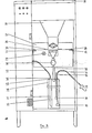
- the mixing sequence is activated as follows: the pressure switch I is de-pressurised with the switch mechanism in a closed circuit situation; this allows a 110 volt A.C supply in parallell to activate the solenoid valve 2,the auger drive motor 3 (milk powder) and the mixer motor 4. Powder is dispensed into the plastic funnel 5 by means of an auger 6 which lies at the bottom of the hopper.7; at the same time as the powder is being dispensed,warm water leaves the metal pipe 8 touching the inside top rim of the funnel 5 and causes the warm water to swirl round the interior of the said funnel 5.
- a plastic paddle 10 activated by the mixer motor 4, vigorously mixes the powder and water.
- the resulting mix drops into a plastic insulated container II by means of a flexible tube 12.
- air pressure within the stainless steel tube I3 operates the pressure switch I thereby placing the switch mechanism in an open circuit situation and the mixing is stopped.
- the mix within the plastic insulated container II is drawn off by the animal by sucking at a teat 14 which is connected to the insulated container II by a flexible tube 15 at the end of which there is a non-return valve 16.
- Water either from the mains or from a tank,enters the machine through a filter 17 and proceeds to the outlet point 18.
- Water is held captive in a plastic tank 19 and as the water level rises,so does a ball float 20 until the inlet valve 21 is closed thus preventing further water entering the tank 19.
- the element heater 22 heats the water in the tank 19 to temperature set by a thermostat 23.
- An outlet pipe 24 takes the heated water to a solenoid valve(Fig 1/2).
- the pressure switch 25 is situated below the water tank and is fixed to the side of the tank support bracket.
- An overflow(25 a) is incorporated to the water tank 19.
- the plastic water tank I9 has a lid 26 of the same material and th one side of this lid 26 there is a small bracket 27 which has fastened to it a micro-switch 28.
- a thin metal rod 30 which penetrates the lid 26 and has a float 31 attached to its other end. If for any reason the water level in the tank 19 drops to a certain level above the water outlet poin 24, the switch 28 will break the power supply to the element heater 22, the circulation fan 32 and components 2, 3 and 4 in Figure I. The "no water” neon will light-up on the instrument panel indicating that the water level in the tank 19 is below the required limit.
- the hopper 33 is secured to the metal motor table 34 by two brackets 35 placed either side of the hopper base .
- the motor table 34 is secured to the metal cabinet(on the inside) by a screw through the slot 36 which fastens to a metal bracket 37.
- the metal bracket 37 is welded to the inside of the cabinet and serves to support and fasten the metal motor table 34.
- the hopper 33 and the motor table 34 may be lifted out of the metal cabinet,as one unit or separately simply by removing the two screws placed in the slots 36,disconecting the water supply to the solenoid valve 39 and removing the electrical connections to the auger drive motor(Figure I item 3),mixer motor(Figure I item 4) and solenoid valve ( Figure I,item 2).
- the hopper 33 and the motor table 34 may be lifted out as one unit or separately.
- the screw on lid 40 has three or more perforations to it; One perforation is to fit a stainless steel tube 42, the other fits a flexible delivery tube 43 and the remaining perforations,allow tubes 44 to enter the insulated container 41.
- the purpose of the insulated container 41 is to keep the mix warm.
- the stainless steel tube 42 has a rim which allows it to "sit" on the lid 40 while the greater part of its body remains in the insulated container 41.
- the mix leaves the mixing chamber 48 via a plastic delivery tube 43 and is deposited in the plastic insulated container.
- the mix is "drawn off" at a teat 49,suction causes the mix to rise up the plastic tube 44; the mix can only travel in the direction of the teat 49 as the base of the plastic tubes 44 are each fitted with a non return valve 50.
- the mixing chamber 48 by means of a gentle outward pulling action, can be separated from its housing. This allows the operator to exchange the original set composing the funnel( Figure 4,ttem 61) ,the mixing chamber 48,delivery tube 43 and insulated plastic container 41, for a spare set of these which are provided with each machine.
- the auger drive motor 56 is fastened to the motor table 52 by means of four screws.
- This cylindrical mixing chamber 62 fits onto a plastic housing 63 causing a seal. From out of the centre of the plastic housing 63, there extends a metal shaft 64 at the end of which there is a plastic paddle which revolves and serves to mix the powder with the water; the plastic paddle is shown as item 65.
- a neck 66 serves to drain the mix-from mixing chamber 62. To this neck 66 there is fitted a hollow flexible tube 67 which conveys the mix to the plastic insulated container below.
- Figure 5 shows the motor table 52, two right angled brackets secured to the motor table 52. These two brackets 35 are equidistant from the centre of the auger drive shaft 55. On the motor table 52 there is a hole 53 which is equidistant from the similar point on both brackets 35.
- Figure 6 shows a drive fork 56 situated at the drive end of the auger; the auger drive pin 54( Figure 5) locks into place with a drive fork 56.
- the locating pin 57 once firmly inserted in the locating hole 53,secures the hopper base 51 to the motor table 52. To release the hopper 51 from the motor table 52,all that is required.is. slight backward tilting motion of the hopper 5I so that the locating pin 57 is outside the locating hole 53. The hopper base 51 can then move slightly forward and the fork 56 is freed from the drive pin 54.
Landscapes
- Life Sciences & Earth Sciences (AREA)
- Environmental Sciences (AREA)
- Animal Husbandry (AREA)
- Biodiversity & Conservation Biology (AREA)
- Basic Packing Technique (AREA)
Priority Applications (1)
| Application Number | Priority Date | Filing Date | Title |
|---|---|---|---|
| EP81301246A EP0060946A1 (fr) | 1981-03-24 | 1981-03-24 | Dispositif pour l'alimentation de bétail |
Applications Claiming Priority (1)
| Application Number | Priority Date | Filing Date | Title |
|---|---|---|---|
| EP81301246A EP0060946A1 (fr) | 1981-03-24 | 1981-03-24 | Dispositif pour l'alimentation de bétail |
Publications (1)
| Publication Number | Publication Date |
|---|---|
| EP0060946A1 true EP0060946A1 (fr) | 1982-09-29 |
Family
ID=8188246
Family Applications (1)
| Application Number | Title | Priority Date | Filing Date |
|---|---|---|---|
| EP81301246A Withdrawn EP0060946A1 (fr) | 1981-03-24 | 1981-03-24 | Dispositif pour l'alimentation de bétail |
Country Status (1)
| Country | Link |
|---|---|
| EP (1) | EP0060946A1 (fr) |
Cited By (1)
| Publication number | Priority date | Publication date | Assignee | Title |
|---|---|---|---|---|
| CN102511405A (zh) * | 2011-12-29 | 2012-06-27 | 石河子大学 | 犊牛饲喂机 |
Citations (6)
| Publication number | Priority date | Publication date | Assignee | Title |
|---|---|---|---|---|
| US3314398A (en) * | 1964-02-01 | 1967-04-18 | Legrain Michel A J | Automatic animal suckling apparatus |
| US3331357A (en) * | 1964-08-17 | 1967-07-18 | Legrain Michel Aime Joseph | Apparatus for the mixing and feeding of liquid food to suckling animals |
| DE7034181U (de) * | 1970-09-15 | 1971-04-22 | Friederici Artur | Vorrichtung zur mechanischen verstellung des mengen-konzentrationsverhaeltnisses bei viehfutter, insbesondere in der kaelbermast. |
| US3625183A (en) * | 1968-03-01 | 1971-12-07 | Adolphe Tartar | Feed dispenser for young animals |
| EP0016685A1 (fr) * | 1979-03-14 | 1980-10-01 | Michel Aimé Joseph Legrain | Dispositif de distribution de liquide par doses déterminées pour machine d'alimentation, à volonté, de jeunes mammifères à la mamelle |
| FR2458997A1 (fr) * | 1979-06-20 | 1981-01-09 | Paturel Eric | Appareil pour la fabrication d'un aliment liquide reconstitue |
-
1981
- 1981-03-24 EP EP81301246A patent/EP0060946A1/fr not_active Withdrawn
Patent Citations (6)
| Publication number | Priority date | Publication date | Assignee | Title |
|---|---|---|---|---|
| US3314398A (en) * | 1964-02-01 | 1967-04-18 | Legrain Michel A J | Automatic animal suckling apparatus |
| US3331357A (en) * | 1964-08-17 | 1967-07-18 | Legrain Michel Aime Joseph | Apparatus for the mixing and feeding of liquid food to suckling animals |
| US3625183A (en) * | 1968-03-01 | 1971-12-07 | Adolphe Tartar | Feed dispenser for young animals |
| DE7034181U (de) * | 1970-09-15 | 1971-04-22 | Friederici Artur | Vorrichtung zur mechanischen verstellung des mengen-konzentrationsverhaeltnisses bei viehfutter, insbesondere in der kaelbermast. |
| EP0016685A1 (fr) * | 1979-03-14 | 1980-10-01 | Michel Aimé Joseph Legrain | Dispositif de distribution de liquide par doses déterminées pour machine d'alimentation, à volonté, de jeunes mammifères à la mamelle |
| FR2458997A1 (fr) * | 1979-06-20 | 1981-01-09 | Paturel Eric | Appareil pour la fabrication d'un aliment liquide reconstitue |
Cited By (1)
| Publication number | Priority date | Publication date | Assignee | Title |
|---|---|---|---|---|
| CN102511405A (zh) * | 2011-12-29 | 2012-06-27 | 石河子大学 | 犊牛饲喂机 |
Similar Documents
| Publication | Publication Date | Title |
|---|---|---|
| US3473516A (en) | Automatic apparatus for preparing and dispensing fluid food | |
| US4456176A (en) | Apparatus for processing and dispensing fertilizer or insecticide | |
| US8763516B2 (en) | Device for feeding milk | |
| CN101980636B (zh) | 包括清洁蒸汽喷管的系统的制备饮料的机器 | |
| CN101980640B (zh) | 包括清洁蒸汽喷管的系统的制备饮料的机器 | |
| EP1200182A1 (fr) | Systeme centralise de melange de bicarbonate | |
| JPS61209537A (ja) | 家畜類に飼料を供給する装置 | |
| GB2142812A (en) | An automatic animal feeder | |
| US8359888B2 (en) | Dispensing system for powdered treating agent for use in a washing machine, and washing machine | |
| KR102044812B1 (ko) | 액상 사료 급여기 | |
| JPH0458297B2 (fr) | ||
| CN108780108B (zh) | 自动分析装置 | |
| US3208431A (en) | Automatic liquid food mixer and suckling animal feeder | |
| US3265036A (en) | Animal liquid feeding apparatus | |
| CN210900916U (zh) | 一种用于鸡养殖的自动喂食装置 | |
| US4170797A (en) | Apparatus for treating waste matter | |
| US20090090140A1 (en) | Dispensing system for powdered treating agent for use in a washing machine | |
| KR101465935B1 (ko) | 자동 사료 급이기의 물공급장치 | |
| CN219209630U (zh) | 一种用于养殖废水处理的自动加药装置 | |
| KR101465936B1 (ko) | 자동 사료 급이기의 물공급장치 | |
| GB1586981A (en) | Calf rearing-random feed equipment | |
| EP0519143B1 (fr) | Perfectionnements apportés aux appareils destinés à l'allaitement animal | |
| KR20180106271A (ko) | 자동 사료 급이기의 이송스크류 구조 | |
| JP2008212055A (ja) | 代用乳溶解装置 | |
| CN221749304U (zh) | 自动奶杯系统 |
Legal Events
| Date | Code | Title | Description |
|---|---|---|---|
| PUAI | Public reference made under article 153(3) epc to a published international application that has entered the european phase |
Free format text: ORIGINAL CODE: 0009012 |
|
| AK | Designated contracting states |
Designated state(s): AT BE CH DE FR GB IT LI LU NL SE |
|
| RAP1 | Party data changed (applicant data changed or rights of an application transferred) |
Owner name: NIXON, ALEXANDER FRANCIS Owner name: NICHOLL, ANTHONY JAMES |
|
| 17P | Request for examination filed |
Effective date: 19830329 |
|
| STAA | Information on the status of an ep patent application or granted ep patent |
Free format text: STATUS: THE APPLICATION IS DEEMED TO BE WITHDRAWN |
|
| 18D | Application deemed to be withdrawn |
Effective date: 19840711 |