EP0060976A1 - Procédé et dispositif pour démarrer un moteur à alcool - Google Patents
Procédé et dispositif pour démarrer un moteur à alcool Download PDFInfo
- Publication number
- EP0060976A1 EP0060976A1 EP82100558A EP82100558A EP0060976A1 EP 0060976 A1 EP0060976 A1 EP 0060976A1 EP 82100558 A EP82100558 A EP 82100558A EP 82100558 A EP82100558 A EP 82100558A EP 0060976 A1 EP0060976 A1 EP 0060976A1
- Authority
- EP
- European Patent Office
- Prior art keywords
- engine
- alcohol
- passageway
- starting motor
- rotational speed
- Prior art date
- Legal status (The legal status is an assumption and is not a legal conclusion. Google has not performed a legal analysis and makes no representation as to the accuracy of the status listed.)
- Granted
Links
- LFQSCWFLJHTTHZ-UHFFFAOYSA-N Ethanol Chemical compound CCO LFQSCWFLJHTTHZ-UHFFFAOYSA-N 0.000 title claims abstract description 30
- 238000000034 method Methods 0.000 title claims abstract description 10
- 239000007788 liquid Substances 0.000 claims abstract description 37
- 239000000446 fuel Substances 0.000 claims abstract description 33
- 239000008246 gaseous mixture Substances 0.000 claims abstract description 15
- 239000000126 substance Substances 0.000 claims abstract description 13
- OKKJLVBELUTLKV-UHFFFAOYSA-N Methanol Chemical compound OC OKKJLVBELUTLKV-UHFFFAOYSA-N 0.000 claims description 70
- LCGLNKUTAGEVQW-UHFFFAOYSA-N Dimethyl ether Chemical compound COC LCGLNKUTAGEVQW-UHFFFAOYSA-N 0.000 claims description 38
- 238000001816 cooling Methods 0.000 claims description 15
- 238000002347 injection Methods 0.000 description 18
- 239000007924 injection Substances 0.000 description 18
- 239000007858 starting material Substances 0.000 description 12
- 239000007789 gas Substances 0.000 description 11
- 238000002485 combustion reaction Methods 0.000 description 8
- 239000002828 fuel tank Substances 0.000 description 5
- 238000011144 upstream manufacturing Methods 0.000 description 5
- 239000000203 mixture Substances 0.000 description 4
- UGFAIRIUMAVXCW-UHFFFAOYSA-N Carbon monoxide Chemical compound [O+]#[C-] UGFAIRIUMAVXCW-UHFFFAOYSA-N 0.000 description 3
- 229910002091 carbon monoxide Inorganic materials 0.000 description 3
- 239000001257 hydrogen Substances 0.000 description 3
- 229910052739 hydrogen Inorganic materials 0.000 description 3
- 239000004615 ingredient Substances 0.000 description 3
- XLYOFNOQVPJJNP-UHFFFAOYSA-N water Substances O XLYOFNOQVPJJNP-UHFFFAOYSA-N 0.000 description 3
- UFHFLCQGNIYNRP-UHFFFAOYSA-N Hydrogen Chemical compound [H][H] UFHFLCQGNIYNRP-UHFFFAOYSA-N 0.000 description 2
- OFBQJSOFQDEBGM-UHFFFAOYSA-N Pentane Chemical compound CCCCC OFBQJSOFQDEBGM-UHFFFAOYSA-N 0.000 description 2
- ATUOYWHBWRKTHZ-UHFFFAOYSA-N Propane Chemical compound CCC ATUOYWHBWRKTHZ-UHFFFAOYSA-N 0.000 description 2
- 238000009835 boiling Methods 0.000 description 2
- 238000006243 chemical reaction Methods 0.000 description 2
- 239000007792 gaseous phase Substances 0.000 description 2
- 239000003502 gasoline Substances 0.000 description 2
- 238000010438 heat treatment Methods 0.000 description 2
- 238000004804 winding Methods 0.000 description 2
- 239000003054 catalyst Substances 0.000 description 1
- 230000003197 catalytic effect Effects 0.000 description 1
- 238000007796 conventional method Methods 0.000 description 1
- 238000010586 diagram Methods 0.000 description 1
- 238000006073 displacement reaction Methods 0.000 description 1
- DQYBDCGIPTYXML-UHFFFAOYSA-N ethoxyethane;hydrate Chemical compound O.CCOCC DQYBDCGIPTYXML-UHFFFAOYSA-N 0.000 description 1
- 239000012530 fluid Substances 0.000 description 1
- 150000002431 hydrogen Chemical class 0.000 description 1
- 239000007791 liquid phase Substances 0.000 description 1
- 239000002075 main ingredient Substances 0.000 description 1
- 238000012986 modification Methods 0.000 description 1
- 230000004048 modification Effects 0.000 description 1
- RXCVUXLCNLVYIA-UHFFFAOYSA-N orthocarbonic acid Chemical compound OC(O)(O)O RXCVUXLCNLVYIA-UHFFFAOYSA-N 0.000 description 1
- 239000001294 propane Substances 0.000 description 1
- 238000009834 vaporization Methods 0.000 description 1
- 230000008016 vaporization Effects 0.000 description 1
Images


Classifications
-
- F—MECHANICAL ENGINEERING; LIGHTING; HEATING; WEAPONS; BLASTING
- F02—COMBUSTION ENGINES; HOT-GAS OR COMBUSTION-PRODUCT ENGINE PLANTS
- F02B—INTERNAL-COMBUSTION PISTON ENGINES; COMBUSTION ENGINES IN GENERAL
- F02B1/00—Engines characterised by fuel-air mixture compression
- F02B1/02—Engines characterised by fuel-air mixture compression with positive ignition
-
- F—MECHANICAL ENGINEERING; LIGHTING; HEATING; WEAPONS; BLASTING
- F02—COMBUSTION ENGINES; HOT-GAS OR COMBUSTION-PRODUCT ENGINE PLANTS
- F02M—SUPPLYING COMBUSTION ENGINES IN GENERAL WITH COMBUSTIBLE MIXTURES OR CONSTITUENTS THEREOF
- F02M1/00—Carburettors with means for facilitating engine's starting or its idling below operational temperatures
- F02M1/16—Other means for enriching fuel-air mixture during starting; Priming cups; using different fuels for starting and normal operation
- F02M1/165—Vaporizing light fractions from the fuel and condensing them for use during starting
Definitions
- This invention relates to a method and apparatus for starting an alcohol internal combustion engine.
- Alcohol Internal combustion engines employing alcohol as fuel are difficult to start, because alcohol is hard to vaporize under low-temperature conditions due to its high boiling point as compared to that of gasoline and its high latent heat of vaporization causes the resulting alcohol/air mixture to be substantially cooled.
- a conventional method of starting an alcohol engine is to crack alcohol into more easily combustible hydrogen and carbon monoxide gases and to supply these gases in addition to alcohol to the engine at starting.
- precise flow control of gaseous fuel may be more difficult than that of liquid fuel.
- alcohol is converted into a high-temperature gaseous mixture containing a substance of relatively-high volatility.
- the gaseous mixture is cooled to provide a liquid condensate containing the relatively highly volatile substance.
- the liquid condensate is supplied to the engine as fuel when the starting motor is in operation.
- FIG. 1 With reference to Fig. 1, there is shown an internal combustion engine 10 which employs methanol as fuel and is equipped with a starting apparatus of the present invention.
- the starting apparatus converts .methanol into a more easily combustible liquid containing dimethyl ether, and supplies it as fuel to the engine during starting.
- the engine 10 has an intake passageway 11 which leads to an engine combustion chamber 12 to supply air to the latter.
- An air cleaner 13 and a throttle valve 14 are provided in the intake passageway 11 in a conventional manner.
- the outlet of a fuel injection valve 15 opens into the intake passageway 11 downstream of the throttle valve 14, the inlet -thereof being connected to a fuel tank 16 via a main fuel supply passageway 17.
- the fuel tank 16 contains liquid methanol.
- a fuel pump 18 is disposed in the passageway 17 to draw methanol from the tank 16 and feed it to the injection valve 15.
- the injection valve 15 discharges methanol into the intake passageway 11 to produce a air-methanol mixture which is then drawn into the combustion chamber 12.
- an electrically-driven or electromagnetic valve 19 is disposed in the fuel passageway 17 to interrupt the supply of methanol from the pump 18 to the injection valve 15 and thus the engine 10.
- the engine 10 has an exhaust passageway 20 connected to the engine combustion chamber 12 to transmit exhaust gas from the chamber 12 to the outside.
- a converter 21 is disposed in the exhaust passageway 20.
- the converter 21 includes an enclosed casing and platinum- based catalyst positioned within the casing.
- the .converter 21 is provided with an inlet which is connected via a passageway 22 to the fuel supply passageway 17 downstream of the pump 1'8 but upstream of the electromagnetic valve 19 to admit methanol into the converter 21 or the inside of the casing thereof.
- the converter 21 receives heat from exhaust gas, thereby converting liquid methanol into a high-temperature gaseous mixture containing dimethyl ether due to its platinum- catalytic action.
- a plurality of passageways may be provided through the converter casing so that engine exhaust can. pass through the passageways to increase the efficiency of heating the converter 21.
- a spacing or path 80 is preferably provided in the exhaust passageway 20 so that a portion of engine exhaust will bypass the passageways through the converter 21.
- a valve 81 is preferably provided in the path 80 to control t.he flow of engine exhaust therethrough and thus the flow through the converter passageways to regulate heat in the converter 21 in response to output signals of a converter-heat sensing device (not shown).
- the converter 21 is provided with an outlet which is connected via a passageway 23 to an upper opening, that is, inlet of a cooling device 24 to conduct the high-temperature gaseous mixture from the converter 21 to the cooling device 24.
- the device 24 cools the introduced gaseous mixture to produce a liquid condensate containing .dimethyl ether.
- a lower opening, that is, outlet of the cooling device 24 leads to an upper opening of a sub-tank 25 through a passageway 26 to supply the liquid condensate to the sub-tank 25.
- the liquid condensate is stored in the sub-tank 25.
- a lower opening of the sub-tank 25 is connected via a passageway 27 to the fuel supply passageway 17 upstream of the injection valve 15 but downstream of the electromagnetic valve 19 to supply the liquid condensate to the injection valve 15 and thus the engine 10.
- An electrically-driven or electromagnetic valve 28 is disposed in the passageway 27 to interrupt the supply of the liquid condensate to the injection valve 15 and thus the engine 10.
- An electrically-driven or electromagnetic, valve 29 is disposed in the passageway 26 to close the passage 26 or substantially close the upper opening of the sub-tank 25.
- One end of an overflow passageway 30 is connected to the passageway 26 upstream of the electromagnetic valve 29, the other end thereof being connected to the passageway 22.
- a check valve 31 is disposed in the overflow passageway 30 in such a manner as to permit fluid flow only from the passageway 26 to the passageway 22. Any liquid condensate which cannot be accommodated in the sub-tank 25 due to the full condition thereof returns to the converter 21 via the overflow passageway 30, check valve 31, and passageway 22.
- the inlet of a gas injection valve 32 is connected via a passageway 33 to the passageway 26 upstream of the electromagnetic valve 29 and the connection of the overflow passageway 30 to the passageway 26.
- the outlet of the gas injection valve 32 opens, into the intake passage 11 upstream of the fuel injection valve 15 but downstream of the throttle valve 14.
- the high-temperature gaseous mixture supplied to the cooling device 24 contains non-condensable gases, such as hydrogen and carbon monoxide. - These gases remain in gaseous phase even in the cooling environment of .the device 24 and are supplied to the engine 10 as a portion of fuel via the passage 33, gas injection valve 32, and the intake passage 11.
- a control unit 40 is provided to control the opening and closing of the electromagnetic valves 19, 28, and 29, which are of the on-off type opening when energized and closing when de-energized.
- the control unit 40 has three output terminals 41, 42, and 43 which are electrically connected to the control terminals of the electromagnetic valves 28, 19, and 29 respectively.
- the control unit 40 has four input terminals 47, 48, 49, and 50.
- a conventional starting motor 70 is provided for driving an engine crankshaft 51 during engine starting.
- a battery 52 is connected across the starting motor 70 via normally-open contacts of a starter relay (magnetic switch) 72 and an ignition switch 71 (key switch).
- the control winding of the starter relay 72 is connected across .the battery 52 via the ignition switch 71 and a starter switch 53. When the switches 53 and 71 are closed, the control winding of the starter relay 72 is thus energized to close the contacts thereof, thereby allowing the starting motor 70 to be also energized.
- the positive terminal of battery 52 is connected via the switch 71 and a switch 54 to the first input terminal 47 of the control unit 40, and is also connected to the fourth input terminal 50 of the control unit 40 via the switch 71.
- the negative terminal of battery 52 is grounded.
- the closing of the ignition switch 71 causes a high-level signal to be supplied to the fourth input terminal 50.
- the switch 54 is interlocked with the starter switch 53 in such a way as to close when the starter switch 53 closes.
- the simultaneous closing of the switch 54 causes a high-level signal to be supplied to the first input terminal 47 of the control unit 40.
- a conventional crank angle sensor 55 including a magnetic pick-up cooperates with the engine crankshaft 51 so as to provide an alternating signal, the frequency of which is proportional to engine rotational speed N (RPM).
- the input terminal of a frequency-to-voltage convertor (F/V convertor) 56 is connected to the crank angle sensor 55 to receive the alternating signal from the crank angle sensor 55.
- the F/V convertor 56 transforms the alternating .signal into a voltage signal, the magnitude of which is proportional to the frequency of the alternating signal and thus engine rotational speed N.
- the output terminal of the F/V convertor 56 is connected to the third input terminal 49 of the control unit 40 to transmit the voltage signal indicative of engine rotational speed N to the third input terminal 49.
- One end of a series combination of resistors 57 and 58 is connected -to the positive terminal of a stabilized dc power source (not shown), the other end of the series combination and the negative terminal of the power source being grounded.
- the junction of the resistors 57 and 58 is connected to the second input terminal 48 of the control unit 40 so that a preset constant voltage is applied to the second input terminal 48 as a reference signal corresponding to a predetermined engine rotational speed N r ef'
- the first input terminal 47 of the control unit 40 is directly connected to the first output terminal 41 of the control unit 40.
- the fourth input terminal 50 of the control unit 40 is directly connected to the third output terminal 43 of the control unit 40.
- the second input terminal 48 of the control unit 40 is connected to the negative input terminal of an operational amplifier 60 via a resistor 59.
- the third input terminal 49 is connected to the positive input terminal of the amplifier 60 via a resistor 61.
- the output terminal of the amplifier 60 is connected to the second output terminal 42 of the control unit 40.
- the operational amplifier 60 serves as a comparator which compares the voltage signal indicative of engine rotational speed N to the reference signal indicative of the predetermined engine rotational speed N ref .
- the comparator 60 provides a high-level signal to the second output terminal 42 of the control unit 40 when engine rotational speed N is equal to or larger than the predetermined value N ref'
- the predetermined value Nref is chosen so that the comparator 60 will discriminate whether or not engine rotational speed N is in a range in which the engine 10 is self-sustaining (self-moving).
- the comparator 60 provides a low-level signal to the second output terminal 42 when engine rotational speed N is lower than the predetermined value N ref .
- Grounding lines in the control unit 40 and those of electromagnetic valves 19, 28, and 29 are omitted for the simplicity of illustration.
- the control unit 40 supplies a high-level signal to the control terminal of the electromagnetic valve 19 to open the latter.
- the control unit 40 supplies a low-level signal to the electromagnetic valve 19 to close the latter.
- the starter switch 53 closes, the switch 54 also closes and the control unit 40 supplies a high-level signal to the control terminal of the .electromagnetic valve 28 to open the latter (provided that the ignition switch 71 is closed).
- the starter switch 53 opens, the switch 54 also opens and the control unit 40 supplies a low-level signal to the electromagnetic valve 28 to close the latter.
- the control unit 40 supplies a high-level signal to the electromagnetic valve 29 to open the latter.
- the control unit 40 supplies a low-level signal to the electromagnetic valve 29 to close the latter.
- the starter switch 53 opens, and the ignition switch 71 closes; the control unit 40 opens the electromagnetic valves 19 and, 29 and closes the electromagnetic valve 28.
- the fuel pump 18 supplies methanol from the fuel tank 16 to the fuel injection valve 15 via the passageway 17 and the electromagnetic valve 19 to inject methanol into the intake passageway 11. Methanol is therefore supplied to the combustion chamber 12 as fuel, with air. Meanwhile, methanol is transported by the pump 18 from the fuel tank 16 to the converter 21 via the passageways 17 and 22, and is heated by engine exhaust, thus being converted into a high-temperature gaseous mixture containing dimethyl ether.
- Heat required for this conversion is obtained predominantly from the exhaust heat of the engine 10, however an electric heater may be employed for heating.
- gaseous mixture created in the converter 21 contains 10 mol % dimethyl ether, 40 mol % hydrogen, 20 mol % carbon hydroxide, 10 mol % water, 5 mol % un-reacted methanol, and others.
- the mixture of these ingredients is supplied via the passageway 23 to the cooling device 24 and is cooled by the device 24.
- condensable ingredients, especially dimethyl ether, of the-high-temperature gaseous mixture condense and separate from the gaseous fraction, the main ingredients of which are water and carbon monoxide. In this way, the cooling device 24 produces a liquid condensate containing dimethyl ether.
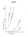
- Figs. 2 and 3 when the pressure is 10 atm, water, methanol, and dimethyl ether. condense at temperatures of about 180°C, 140°C, and 46°C, respectively. Dimethyl ether is in the gaseous phase at normal temperatures and pressures, but changes to liquid phase when pressurized. The percentage of dimethyl ether in the liquid condensate is 60% by weight, or 40 mol %.
- the liquid condensate provided by the cooling device 24 is transported through the passageway 26 to the sub-tank 25 and collects in the sub-tank 25.
- additional liquid is returned to the converter 21 via the overflow passageway 30 and check valve 31.
- the overflowing liquid condensate fuel may be supplied to the engine 10 via the fuel injection valve 15.
- the control unit 40 closes the electromagnetic valve 29 to maintain pressure in the sub-tank 25 at a relatively high level. In this case, since engine rotational speed N is of course lower than the predetermined value N ref and the starter switch 53 is open, the control unit 40 also closes both the electromagnetic valves 19 and 28.
- the control unit 40 opens both the -electromagnetic valves 28 and 29 and keeps the electromagnetic valve 19 closed until engine rotational speed N reaches the predetermined value N ref .
- N ref the predetermined value
- only the liquid condensate containing dimethyl ether is supplied from the sub-tank 25 to the fuel injection valve 15 via the passageways 27 and 17 to be injected into the intake passageway 11. In this way, the supply of methanol to the engine 10 is interrupted while only the liquid condensate is supplied to the engine 10 as fuel.
- dimethyl ether is much more volatile than methanol or pentane, the low boiling point ingredient of gasoline, and has about 600 mmHg vapor pressure at a temperature of -30°C, so that dimethyl ether is more easily combustible and the engine 10 can be easily started even under low-temperature conditions.
- the vapor pressure of dimethyl ether is, for example, about one half of that of propane, high pressure rating is not required of the sub-tank 25.
- dimethyl ether Since dimethyl ether has a calorific value of about 7,000 Kcal/Kg, even under low-temperature conditions its supply rate of about 0.4 cc/S is sufficient to start an automotive engine in the case of its total displacement of 2,000 cc. Thus, the volume of sub-tank 25 can be extremely small even if the need for more than one attempt to start is taken into account.
- both dimethyl ether and methanol may also be supplied to the engine.
- the control unit 40 opens the electromagnetic valve 19 to supply methanol from the fuel tank 16 to the fuel injection valve 15.
- the starter switch 53 is usually opened as soon as engine rotational speed N reaches the predetermined value N ref . Therefore, just after engine starting, the control unit 40 usually closes the electromagnetic valve 28 to stop the supply of the liquid condensate from the sub-tank 25 to the fuel injection valve 15 and the engine 10.
- the control unit 40 usually closes the electromagnetic valve 28 to stop the supply of the liquid condensate from the sub-tank 25 to the fuel injection valve 15 and the engine 10.
- fuel is not limited to methanol, but may be other.
- alcohol is not limited to dimethyl ether, but may be other substances.
Landscapes
- Engineering & Computer Science (AREA)
- Chemical & Material Sciences (AREA)
- Combustion & Propulsion (AREA)
- Mechanical Engineering (AREA)
- General Engineering & Computer Science (AREA)
- Output Control And Ontrol Of Special Type Engine (AREA)
Applications Claiming Priority (2)
| Application Number | Priority Date | Filing Date | Title |
|---|---|---|---|
| JP38734/81 | 1981-03-19 | ||
| JP56038734A JPS57153952A (en) | 1981-03-19 | 1981-03-19 | Starting device of alcohol engine |
Publications (2)
| Publication Number | Publication Date |
|---|---|
| EP0060976A1 true EP0060976A1 (fr) | 1982-09-29 |
| EP0060976B1 EP0060976B1 (fr) | 1985-06-19 |
Family
ID=12533548
Family Applications (1)
| Application Number | Title | Priority Date | Filing Date |
|---|---|---|---|
| EP82100558A Expired EP0060976B1 (fr) | 1981-03-19 | 1982-01-27 | Procédé et dispositif pour démarrer un moteur à alcool |
Country Status (4)
| Country | Link |
|---|---|
| US (1) | US4413594A (fr) |
| EP (1) | EP0060976B1 (fr) |
| JP (1) | JPS57153952A (fr) |
| DE (1) | DE3264158D1 (fr) |
Cited By (7)
| Publication number | Priority date | Publication date | Assignee | Title |
|---|---|---|---|---|
| EP0419743A1 (fr) * | 1989-09-29 | 1991-04-03 | Her Majesty The Queen In Right Of New Zealand | Alimentation en carburant et système de contrôle pour moteurs à allumage par compression |
| WO1994024432A1 (fr) * | 1993-04-16 | 1994-10-27 | Engelhard Corporation | Procede et appareil de modification du carburant pour reduire les emissions polluantes des moteurs a combustion interne |
| EP0801225A1 (fr) * | 1996-04-09 | 1997-10-15 | Jenbacher Energiesysteme Ag | Fluide d'allumage |
| RU2135798C1 (ru) * | 1997-12-22 | 1999-08-27 | Аллилуев Борис Федорович | Способ конвертирования поршневого бензинового двигателя внутреннего сгорания в дизельный двигатель |
| RU2135813C1 (ru) * | 1998-02-13 | 1999-08-27 | Аллилуев Борис Федорович | Топливная система дизеля для работы на диметиловом эфире |
| WO2000077383A1 (fr) * | 1999-06-15 | 2000-12-21 | Daimlerchrysler Ag | Installation d'alimentation en carburant |
| WO2000077381A1 (fr) * | 1999-06-15 | 2000-12-21 | Daimlerchrysler Ag | Systeme d'alimentation en carburant |
Families Citing this family (13)
| Publication number | Priority date | Publication date | Assignee | Title |
|---|---|---|---|---|
| US4408572A (en) * | 1981-07-27 | 1983-10-11 | Conoco Inc. | Ether cold starter in alcohol fuel treatment and distribution apparatus and method |
| JPH0388957A (ja) * | 1989-08-22 | 1991-04-15 | New Zealand Government | 圧縮点火エンジンの燃料供給装置及びその制御装置 |
| US5038730A (en) * | 1989-08-09 | 1991-08-13 | Fuji Jukogyo Kabushiki Kaisha | Start control system for alcohol engine |
| DE19713841C1 (de) * | 1997-04-04 | 1998-11-12 | Dornier Gmbh | Verfahren zur On-Board-Fraktionierung von motorischem Kraftstoff |
| JP2002276473A (ja) * | 2001-03-22 | 2002-09-25 | Isuzu Motors Ltd | ジメチルエーテルエンジンの燃料供給システム |
| CN1327121C (zh) * | 2002-12-05 | 2007-07-18 | 天津大学 | 超低排放甲醇燃料发动机 |
| JP4382722B2 (ja) * | 2005-08-04 | 2009-12-16 | 本田技研工業株式会社 | 内燃機関システム |
| US8015951B2 (en) * | 2006-03-17 | 2011-09-13 | Ford Global Technologies, Llc | Apparatus with mixed fuel separator and method of separating a mixed fuel |
| US8539914B2 (en) * | 2010-04-08 | 2013-09-24 | Ford Global Technologies, Llc | Method for operating an engine with a fuel reformer |
| KR101305611B1 (ko) * | 2011-12-08 | 2013-09-09 | 기아자동차주식회사 | 차량의 연료 공급 시스템 |
| US9739243B2 (en) * | 2012-02-10 | 2017-08-22 | Ford Gloabl Technologies, LLC | Methods and systems for fuel vapor control |
| JP2017008900A (ja) * | 2015-06-26 | 2017-01-12 | いすゞ自動車株式会社 | 天然ガスエンジン及び天然ガスエンジンの運転方法 |
| JP7431441B2 (ja) * | 2020-03-17 | 2024-02-15 | 学校法人 中央大学 | 流体圧アクチュエータ駆動システム及び流体圧アクチュエータ駆動方法 |
Citations (4)
| Publication number | Priority date | Publication date | Assignee | Title |
|---|---|---|---|---|
| GB220291A (fr) * | 1923-08-08 | 1925-07-23 | Hugo Junkers | |
| GB1346702A (en) * | 1972-08-30 | 1974-02-13 | Mobil Oil Corp | Fuel supply system for reduced exhaust emission |
| FR2306343A1 (fr) * | 1975-03-31 | 1976-10-29 | Nissan Motor | Dispositif d'alimentation pour moteur a combustion |
| EP0022876A1 (fr) * | 1978-12-28 | 1981-01-28 | Nissan Motor Co., Ltd. | Demarreur pour moteur a alcool |
Family Cites Families (5)
| Publication number | Priority date | Publication date | Assignee | Title |
|---|---|---|---|---|
| US3783841A (en) * | 1971-10-04 | 1974-01-08 | Ethyl Corp | Fuel system |
| US4170200A (en) * | 1974-06-14 | 1979-10-09 | Nippondenso Co., Ltd. | Internal combustion engine with reformed gas generator |
| US4131086A (en) * | 1974-07-20 | 1978-12-26 | Nippon Soken, Inc. | Fuel reforming apparatus for use with internal combustion engine |
| JPS555403A (en) * | 1978-06-22 | 1980-01-16 | Nissan Motor Co Ltd | Controller for fuel metering device |
| US4204511A (en) * | 1979-01-19 | 1980-05-27 | Outboard Marine Corporation | Combination ignition switch and fuel priming system |
-
1981
- 1981-03-19 JP JP56038734A patent/JPS57153952A/ja active Pending
-
1982
- 1982-01-18 US US06/340,276 patent/US4413594A/en not_active Expired - Fee Related
- 1982-01-27 DE DE8282100558T patent/DE3264158D1/de not_active Expired
- 1982-01-27 EP EP82100558A patent/EP0060976B1/fr not_active Expired
Patent Citations (4)
| Publication number | Priority date | Publication date | Assignee | Title |
|---|---|---|---|---|
| GB220291A (fr) * | 1923-08-08 | 1925-07-23 | Hugo Junkers | |
| GB1346702A (en) * | 1972-08-30 | 1974-02-13 | Mobil Oil Corp | Fuel supply system for reduced exhaust emission |
| FR2306343A1 (fr) * | 1975-03-31 | 1976-10-29 | Nissan Motor | Dispositif d'alimentation pour moteur a combustion |
| EP0022876A1 (fr) * | 1978-12-28 | 1981-01-28 | Nissan Motor Co., Ltd. | Demarreur pour moteur a alcool |
Non-Patent Citations (1)
| Title |
|---|
| AUTOMOBILTECHNISCHE ZEITSCHRIFT, vol. 81, no. 6, June 1979, pages 279-282, Stuttgart (DE); * |
Cited By (9)
| Publication number | Priority date | Publication date | Assignee | Title |
|---|---|---|---|---|
| EP0419743A1 (fr) * | 1989-09-29 | 1991-04-03 | Her Majesty The Queen In Right Of New Zealand | Alimentation en carburant et système de contrôle pour moteurs à allumage par compression |
| WO1994024432A1 (fr) * | 1993-04-16 | 1994-10-27 | Engelhard Corporation | Procede et appareil de modification du carburant pour reduire les emissions polluantes des moteurs a combustion interne |
| EP0801225A1 (fr) * | 1996-04-09 | 1997-10-15 | Jenbacher Energiesysteme Ag | Fluide d'allumage |
| RU2135798C1 (ru) * | 1997-12-22 | 1999-08-27 | Аллилуев Борис Федорович | Способ конвертирования поршневого бензинового двигателя внутреннего сгорания в дизельный двигатель |
| RU2135813C1 (ru) * | 1998-02-13 | 1999-08-27 | Аллилуев Борис Федорович | Топливная система дизеля для работы на диметиловом эфире |
| WO2000077383A1 (fr) * | 1999-06-15 | 2000-12-21 | Daimlerchrysler Ag | Installation d'alimentation en carburant |
| WO2000077381A1 (fr) * | 1999-06-15 | 2000-12-21 | Daimlerchrysler Ag | Systeme d'alimentation en carburant |
| US6571748B2 (en) | 1999-06-15 | 2003-06-03 | Daimlerchrysler Ag | Fuel supply system |
| US6622664B2 (en) | 1999-06-15 | 2003-09-23 | Daimler Chrysler Ag | Fuel supply system |
Also Published As
| Publication number | Publication date |
|---|---|
| EP0060976B1 (fr) | 1985-06-19 |
| JPS57153952A (en) | 1982-09-22 |
| US4413594A (en) | 1983-11-08 |
| DE3264158D1 (en) | 1985-07-25 |
Similar Documents
| Publication | Publication Date | Title |
|---|---|---|
| US4413594A (en) | Method and apparatus for starting an alcohol engine | |
| US5148776A (en) | Coordinated water and fuel injection system | |
| CA1198494A (fr) | Injection direct de gaz de petrole liquefie | |
| US4147142A (en) | Fuel modification system for internal combustion engines | |
| US4242992A (en) | Internal combustion engine with fuel injectors | |
| US20230243319A1 (en) | Thermal choke, autostart generator system, and method of use thereof | |
| US5368001A (en) | Fuel handling system | |
| US20010003977A1 (en) | Fuel injection system for internal combustion engines and its method of control | |
| US4345141A (en) | Electrical fuel preheater assembly | |
| US20080196703A1 (en) | Vapor fueled engine | |
| US4519341A (en) | Heated water-alcohol injection system for carbureted internal combustion engines | |
| US4421280A (en) | Fuel injector | |
| FR2374517A1 (fr) | Circuit d'enrichissement de demarrage pour systeme electronique de commande d'alimentation en combustible pour moteur a combustion interne | |
| EP0398898A1 (fr) | Systeme de regulation de l'injection du carburant. | |
| GB1580158A (en) | Pre-vaporising fuel system | |
| CA1042294A (fr) | Dispositif de dosage du carburant pour moteurs a combustion interne et systemes munis d'un tel dispositif | |
| CA1063453A (fr) | Systeme d'alimentation et de dosage de combustible liquide vaporise | |
| US4388904A (en) | Air-fuel ratio control system | |
| GB2127483A (en) | I. C. engine fuel vaporizing system | |
| US4441475A (en) | Supplementary fuel system for enhancing low temperature engine operation | |
| KR930002637Y1 (ko) | 알콜 엔진의 보조 연료 공급 장치 | |
| JP2794295B2 (ja) | ガスエンジン発電装置 | |
| AU5869186A (en) | Internal combustion engine pollutant control system | |
| NL2000123C2 (nl) | Stelsel voor het injecteren van vloeibare damp. | |
| FR2514422A1 (fr) | Detendeur-vaporisateur a injection electronique pour moteur a gaz de petrole liquefie |
Legal Events
| Date | Code | Title | Description |
|---|---|---|---|
| PUAI | Public reference made under article 153(3) epc to a published international application that has entered the european phase |
Free format text: ORIGINAL CODE: 0009012 |
|
| 17P | Request for examination filed |
Effective date: 19820127 |
|
| AK | Designated contracting states |
Designated state(s): DE FR GB |
|
| GRAA | (expected) grant |
Free format text: ORIGINAL CODE: 0009210 |
|
| AK | Designated contracting states |
Designated state(s): DE FR GB |
|
| RAP2 | Party data changed (patent owner data changed or rights of a patent transferred) |
Owner name: NISSAN MOTOR CO., LTD. |
|
| REF | Corresponds to: |
Ref document number: 3264158 Country of ref document: DE Date of ref document: 19850725 |
|
| ET | Fr: translation filed | ||
| PLBE | No opposition filed within time limit |
Free format text: ORIGINAL CODE: 0009261 |
|
| STAA | Information on the status of an ep patent application or granted ep patent |
Free format text: STATUS: NO OPPOSITION FILED WITHIN TIME LIMIT |
|
| 26N | No opposition filed | ||
| PGFP | Annual fee paid to national office [announced via postgrant information from national office to epo] |
Ref country code: FR Payment date: 19911223 Year of fee payment: 11 |
|
| PGFP | Annual fee paid to national office [announced via postgrant information from national office to epo] |
Ref country code: GB Payment date: 19930118 Year of fee payment: 12 |
|
| PGFP | Annual fee paid to national office [announced via postgrant information from national office to epo] |
Ref country code: DE Payment date: 19930209 Year of fee payment: 12 |
|
| PG25 | Lapsed in a contracting state [announced via postgrant information from national office to epo] |
Ref country code: FR Effective date: 19930930 |
|
| REG | Reference to a national code |
Ref country code: FR Ref legal event code: ST |
|
| PG25 | Lapsed in a contracting state [announced via postgrant information from national office to epo] |
Ref country code: GB Effective date: 19940127 |
|
| GBPC | Gb: european patent ceased through non-payment of renewal fee |
Effective date: 19940127 |
|
| PG25 | Lapsed in a contracting state [announced via postgrant information from national office to epo] |
Ref country code: DE Effective date: 19941001 |