EP0060977B1 - Procédé de fabrication d'une tête magnétique à elements multiples - Google Patents
Procédé de fabrication d'une tête magnétique à elements multiples Download PDFInfo
- Publication number
- EP0060977B1 EP0060977B1 EP82100711A EP82100711A EP0060977B1 EP 0060977 B1 EP0060977 B1 EP 0060977B1 EP 82100711 A EP82100711 A EP 82100711A EP 82100711 A EP82100711 A EP 82100711A EP 0060977 B1 EP0060977 B1 EP 0060977B1
- Authority
- EP
- European Patent Office
- Prior art keywords
- transducing
- assemblies
- assembly
- magnetic
- depositing
- Prior art date
- Legal status (The legal status is an assumption and is not a legal conclusion. Google has not performed a legal analysis and makes no representation as to the accuracy of the status listed.)
- Expired
Links
- 230000002463 transducing effect Effects 0.000 title claims description 26
- 238000004519 manufacturing process Methods 0.000 title claims description 9
- 238000000429 assembly Methods 0.000 claims description 26
- 230000000712 assembly Effects 0.000 claims description 26
- 229910000859 α-Fe Inorganic materials 0.000 claims description 19
- 238000000151 deposition Methods 0.000 claims description 12
- 230000004907 flux Effects 0.000 claims description 12
- 239000004020 conductor Substances 0.000 claims description 11
- 238000000034 method Methods 0.000 claims description 9
- 239000000463 material Substances 0.000 claims description 8
- 239000011810 insulating material Substances 0.000 claims description 7
- 238000005520 cutting process Methods 0.000 claims description 4
- 230000000295 complement effect Effects 0.000 claims description 3
- 238000003754 machining Methods 0.000 claims description 3
- 238000004804 winding Methods 0.000 claims description 3
- 239000011521 glass Substances 0.000 description 6
- 239000010409 thin film Substances 0.000 description 6
- 229910052737 gold Inorganic materials 0.000 description 4
- 239000010931 gold Substances 0.000 description 4
- 229910000889 permalloy Inorganic materials 0.000 description 4
- RYGMFSIKBFXOCR-UHFFFAOYSA-N Copper Chemical compound [Cu] RYGMFSIKBFXOCR-UHFFFAOYSA-N 0.000 description 3
- 229910052802 copper Inorganic materials 0.000 description 3
- 239000010949 copper Substances 0.000 description 3
- PCHJSUWPFVWCPO-UHFFFAOYSA-N gold Chemical compound [Au] PCHJSUWPFVWCPO-UHFFFAOYSA-N 0.000 description 3
- VYPSYNLAJGMNEJ-UHFFFAOYSA-N Silicium dioxide Chemical compound O=[Si]=O VYPSYNLAJGMNEJ-UHFFFAOYSA-N 0.000 description 2
- 238000005530 etching Methods 0.000 description 2
- 239000012530 fluid Substances 0.000 description 2
- 238000001771 vacuum deposition Methods 0.000 description 2
- XAGFODPZIPBFFR-UHFFFAOYSA-N aluminium Chemical compound [Al] XAGFODPZIPBFFR-UHFFFAOYSA-N 0.000 description 1
- 229910052782 aluminium Inorganic materials 0.000 description 1
- 230000008021 deposition Effects 0.000 description 1
- 238000009713 electroplating Methods 0.000 description 1
- 238000003780 insertion Methods 0.000 description 1
- 230000037431 insertion Effects 0.000 description 1
- 239000012212 insulator Substances 0.000 description 1
- 230000008018 melting Effects 0.000 description 1
- 238000002844 melting Methods 0.000 description 1
- 239000000203 mixture Substances 0.000 description 1
- 238000012986 modification Methods 0.000 description 1
- 230000004048 modification Effects 0.000 description 1
- 238000002161 passivation Methods 0.000 description 1
- 238000000206 photolithography Methods 0.000 description 1
- 229920002120 photoresistant polymer Polymers 0.000 description 1
- 238000001020 plasma etching Methods 0.000 description 1
- 235000012239 silicon dioxide Nutrition 0.000 description 1
- 239000000377 silicon dioxide Substances 0.000 description 1
- 238000004544 sputter deposition Methods 0.000 description 1
- 238000003860 storage Methods 0.000 description 1
Images


Classifications
-
- G—PHYSICS
- G11—INFORMATION STORAGE
- G11B—INFORMATION STORAGE BASED ON RELATIVE MOVEMENT BETWEEN RECORD CARRIER AND TRANSDUCER
- G11B5/00—Recording by magnetisation or demagnetisation of a record carrier; Reproducing by magnetic means; Record carriers therefor
- G11B5/127—Structure or manufacture of heads, e.g. inductive
- G11B5/29—Structure or manufacture of unitary devices formed of plural heads for more than one track
- G11B5/295—Manufacture
-
- G—PHYSICS
- G11—INFORMATION STORAGE
- G11B—INFORMATION STORAGE BASED ON RELATIVE MOVEMENT BETWEEN RECORD CARRIER AND TRANSDUCER
- G11B5/00—Recording by magnetisation or demagnetisation of a record carrier; Reproducing by magnetic means; Record carriers therefor
- G11B5/127—Structure or manufacture of heads, e.g. inductive
- G11B5/17—Construction or disposition of windings
-
- G—PHYSICS
- G11—INFORMATION STORAGE
- G11B—INFORMATION STORAGE BASED ON RELATIVE MOVEMENT BETWEEN RECORD CARRIER AND TRANSDUCER
- G11B5/00—Recording by magnetisation or demagnetisation of a record carrier; Reproducing by magnetic means; Record carriers therefor
- G11B5/127—Structure or manufacture of heads, e.g. inductive
- G11B5/187—Structure or manufacture of the surface of the head in physical contact with, or immediately adjacent to the recording medium; Pole pieces; Gap features
- G11B5/193—Structure or manufacture of the surface of the head in physical contact with, or immediately adjacent to the recording medium; Pole pieces; Gap features the pole pieces being ferrite or other magnetic particles
Definitions
- This invention relates to multi-element magnetic transducing heads for use, for example, in high track density magnetic disk storage system.
- Multi-element magnetic transducing heads have been developed for magnetic tape machines, for reading or recording data on a multiplicity of tape tracks simultaneously.
- Some magnetic disk files have employed similar multitrack magnetic heads, but their use has been limited to applications permitting a relatively large vertical dimension, requiring in particular relatively large spacings between adjacent disks of a multiple disk store.
- An example is shown in US Patent 3,579,214, which describes a multiple head assembly in which each head has an associated wound coil.
- Such coils occupy a significant amount of space, and in applications involving very closely spaced multiple recording media, such as flexible or floppy disk files in which adjacent disks are closely adjacent, space considerations are significant.
- the density of the data tracks on the surface of each disk is a major concern.
- German specification No. 2,507,557 discloses a method of manufacturing a multiple element magnetic transducing head comprising forming a magnetic assembly comprising a pair of elongate ferrite components bonded together to define an elongate magnetic gap therebetween; cutting the assembly to form a pattern of slots extending into the assembly at regularly spaced intervals along its length; fitting a series of plates into the slots; bonding the plates in the slots with a low melting point glass and thereafter machining the assembly to a required configuration.
- Japanese specifications No. 51-115810 discloses a method of manufacturing a multiple element magnetic transducing head from two similar magnetic assemblies.
- Each assembly comprises a ferrite block having a row of parallel, spaced grooves formed in it to provide a row of lands.
- the top edge of each land is recessed and a U-shaped bridge piece is secured to the top edge so that a magnetic circuit, including a magnetic gap, is formed by the land and the bridge piece.
- the two assemblies are inter-fitted and secured together.
- U.S. specification No. 4,114,259 discloses a magnetic head assembly in which the component assemblies are located relative to one another during manufacture by reference surfaces provided on the assemblies.
- U.S. specification No. 3,626,396 discloses a linear array of recording heads, each comprising a copper wedge with ferrite pole pieces extending along the sloping faces.
- the transducer gap is formed at the apex of the wedge.
- the magnetic circuit is completed by a magnetic layer deposited over an insulating layer formed on the base of the wedge.
- To sense changes of magnetic flux in the circuit a copper conductor is deposited on the base of the wedge before the insulating layer is formed thereon. The conductor forms a single turn winding linked with the magnetic circuit.
- Japanese specification No. JA-A-51-113721 discloses a method of manufacturing a multiple element magnetic transducing head comprising forming two similar magnetic assemblies each comprising a pair of elongate ferrite components bonded together to define an elongate magnetic gap therebetween; cutting the two assemblies to form complementary patterns of slots extending into the assemblies to interrupt the gap at regularly spaced intervals along its length to define in each assembly a number of regularly spaced, individually gapped, transducing sections; inter-fitting the two assemblies with the slots of each assembly accommodating the transducing section of the other assembly; and bonding the inter-fitting transducer sections into the slots to secure the assemblies together as a unitary structure with the transducing sections separated from one another by a bonding material.
- the transducer comprises a generally rectangular shaped magnetic core, one limb of which is encircled by a multiple turn conductive coil.
- the coil is formed by deposition techniques and includes a first plurality of thin coil-turn-forming-pieces formed by etching away unwanted portions of a deposited-gold layer. A layer of insulating material is then deposited over the coil-turn-forming-pieces leaving the end bare.
- the core structure is then formed by a series of deposition steps and embedded in a layer of polymide. Openings are then etched through the polymide layer in registry with the bare ends of the coil-turn-forming-pieces and the openings filled by electro-plating with gold to form the side riser portions of the coil turns. A sputtering process is then used to deposit a second plurality of gold coil-turn-forming-pieces inter-connecting the side risers.
- the invention provides a method of manufacturing a multiple element magnetic transducing head comprising forming two similar magnetic assemblies each comprising a pair of elongate ferrite components bonded together to define an elongate magnetic gap therebetween; cutting the two assemblies to form complementary patterns of slots extending into the assemblies to interrupt the gap at regularly spaced intervals along its length to define in each assembly a number of regularly spaced, individually gapped, transducing section; inter-fitting the two assemblies with the slots of each assembly accommodating the transducing section of the other assembly; bonding the inter-fitting transducer sections into the slots to secure the assemblies together as a unitary structure with the transducing sections separated from one another by the bonding material; said method being characterised by the steps of machining the unitary structure to form a head assembly comprising a row of magnetically separated transducer sections having a profiled upper transducing surface and a lower surface; and thereafter completing each transducer section by depositing a first predetermined pattern of conductor elements on the lower surface thereof, depositing insulating
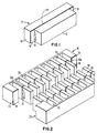
- a rectangular ferrite block 10 is joined to a shaped ferrite section 12 by means of a high temperature glass in a fluid state to form a sandwich assembly 14.
- the ferrite section 12 includes a channel 16 that determines the back gap of the multi-element magnetic head that is being formed.
- the glass bonding layer or shim 18 serves to define transducing gaps 20-an, respectively, for each of a multiplicity of head elements of the finished magnetic head assembly.
- the glass shim 18 also is disposed on reliefs or reference surfaces 22, 24 at the ends of the ferrite block 10 to enable proper engagement of the sandwich assembly 14 with a second ferrite sandwich assembly 26.
- uniformly spaced rectangular slots 30 are machined and cut through each of the ferrite sections and glass bonds into the ferrite blocks of the sandwich assemblies, thereby forming alternating fingers or projections 28.
- the projections 28 are dimensioned to provide a close fit with the opposing slots 30, with the allowance of relatively small spacing between the projections and slots to enable insertion of a low temperature bonding glass 32 in a fluid state.
- the sandwich assemblies are aligned and positioned in engaging relation so that the relief surfaces 22 and 24 abut the opposing relief surfaces of the sandwich assembly 26.
- the top and bottom surfaces of the joined sandwich assemblies are lapped to achieve a low contoured head- assembly, as depicted in Fig. 4.
- the top surface 33 is lapped and polished to produce a low contoured arcuate configuration, in which the vertical height from the bottom surface 34 to the contoured face is substantially less than the width or length of said head assembly.
- the bottom surface 34 of the head assembly is lapped and polished to a high degree of flatness so as to accept thin film layers that will form the conductive coil and a flux path for the magnetic head circuitry.
- the segments 35 of the head structure shown in Fig. 4 represent discrete head elements, including discrete transducing gaps 20.
- a patterned conductive thin film layer 36 which may be gold or copper for example, is vacuum deposited on the bottom surface 34 of the head assembly (see Fig. 6).
- An insulating layer 38 of A1 2 0 3 is sputter-deposited on the conductive layer 36, leaving the end portions of the layer 36 exposed.
- a thick bar type layer 40 of Permalloy, of about 3 mil thickness, is then sputter-deposited on the insulator 38 to provide a flux path for the magnetic circuit of the head. The ends of the flux path bar 40 are in intimate contact with the ferrite surface of the head assembly, as shown in Fig. 5.
- insulating layer 42 of AI 2 0 3 is deposited on the Permalloy flux path bar, still leaving the ends of the conductive layer 36 exposed.
- a second patterned conductive thin film layer 44 is then formed by vacuum deposition, by way of example, so as to connect with the exposed ends of the first conductive layer 36, thereby closing a conductive path which is disposed around the flux bar 40.
- an insulating passivation layer 46 which may be A1 2 0 3 , is sputter-deposited to complete an assembly of the multi-turn thin film coil and flux path bar for each head element.
- the invention is not limited to the specific materials, processes or dimensions recited above.
- the conductive elements of the coil may be made from aluminum or other conductive materials and may be electroplated, patterned by etching, lift-off, or plate-through instead of by vacuum deposition.
- the insulating layers may be made of polymide or photoresist, and by photolithography and baking.
- laminated Permalloy and silicon dioxide layers may be used and may be patterned by reactive ion etching. Other changes and modifications may be made within the scope of the invention.
Landscapes
- Engineering & Computer Science (AREA)
- Manufacturing & Machinery (AREA)
- Magnetic Heads (AREA)
Claims (3)
Applications Claiming Priority (2)
| Application Number | Priority Date | Filing Date | Title |
|---|---|---|---|
| US245562 | 1981-03-19 | ||
| US06/245,562 US4373173A (en) | 1981-03-19 | 1981-03-19 | Multi-element head assembly |
Publications (3)
| Publication Number | Publication Date |
|---|---|
| EP0060977A2 EP0060977A2 (fr) | 1982-09-29 |
| EP0060977A3 EP0060977A3 (en) | 1983-02-16 |
| EP0060977B1 true EP0060977B1 (fr) | 1986-11-12 |
Family
ID=22927165
Family Applications (1)
| Application Number | Title | Priority Date | Filing Date |
|---|---|---|---|
| EP82100711A Expired EP0060977B1 (fr) | 1981-03-19 | 1982-02-02 | Procédé de fabrication d'une tête magnétique à elements multiples |
Country Status (4)
| Country | Link |
|---|---|
| US (1) | US4373173A (fr) |
| EP (1) | EP0060977B1 (fr) |
| JP (1) | JPS57158009A (fr) |
| DE (1) | DE3274313D1 (fr) |
Families Citing this family (11)
| Publication number | Priority date | Publication date | Assignee | Title |
|---|---|---|---|---|
| US4914537A (en) * | 1987-04-24 | 1990-04-03 | Pioneer Electric Corporation | Magnetic head device having a bridge core |
| NL8901712A (nl) * | 1989-01-30 | 1990-08-16 | Philips Nv | Longitudinaal magneetband recording systeem alsmede een magneetbandapparaat geschikt voor toepassing in het systeem alsmede een magneetkop geschikt voor toepassing in het magneetbandapparaat. |
| JP2674220B2 (ja) * | 1989-06-27 | 1997-11-12 | ソニー株式会社 | 磁気ヘッドの製造方法 |
| US5059278A (en) * | 1990-09-28 | 1991-10-22 | Seagate Technology | Selective chemical removal of coil seed-layer in thin film head magnetic transducer |
| US5220473A (en) * | 1991-05-08 | 1993-06-15 | Eastman Kodak Company | Multitrack magnetic head assembly having a tape-engaging surface contoured for continuous in-contact recording |
| US5506737A (en) * | 1994-07-05 | 1996-04-09 | Industrial Technology Research Institute | High-density electronic head |
| US5703740A (en) * | 1995-08-24 | 1997-12-30 | Velocidata, Inc. | Toroidal thin film head |
| US6195232B1 (en) | 1995-08-24 | 2001-02-27 | Torohead, Inc. | Low-noise toroidal thin film head with solenoidal coil |
| US6018444A (en) * | 1997-10-28 | 2000-01-25 | Hewlett-Packard Company | Batch fabricated servo write head having low write-gap linewidth variation |
| US6088184A (en) * | 1998-06-16 | 2000-07-11 | International Business Machines Corporation | Apparatus and method for the control and positioning of magnetic recording heads in an azimuth recording system |
| US6838195B2 (en) * | 2002-06-28 | 2005-01-04 | Seagate Technology Llc | Increased packing density in self-organized magnetic tray |
Family Cites Families (10)
| Publication number | Priority date | Publication date | Assignee | Title |
|---|---|---|---|---|
| US3353261A (en) * | 1964-12-30 | 1967-11-21 | Ibm | Method of making a multitrack magnetic transducer head |
| US3626396A (en) * | 1968-10-03 | 1971-12-07 | Ibm | Thin-film magnetic recording head |
| GB1409889A (en) * | 1972-12-29 | 1975-10-15 | Data Recording Instr Co | Manufacture of multi-track magnetic heads |
| US3986210A (en) * | 1973-02-20 | 1976-10-12 | Matsushita Electric Industrial Co., Ltd. | Magnetic head device using printed circuit techniques |
| JPS5039920A (fr) * | 1973-08-15 | 1975-04-12 | ||
| JPS50115811A (fr) * | 1974-02-23 | 1975-09-10 | ||
| JPS51113721A (en) * | 1975-03-31 | 1976-10-07 | Hitachi Ltd | Production method of magnetic head |
| US4084199A (en) * | 1976-10-26 | 1978-04-11 | Spin Physics, Inc. | High density multitrack magnetic head |
| US4217613A (en) * | 1978-11-06 | 1980-08-12 | Rca Corporation | Magnetic transducer head core |
| US4357640A (en) * | 1980-10-24 | 1982-11-02 | Nortronics Company, Inc. | Thin film magnetic transducer |
-
1981
- 1981-03-19 US US06/245,562 patent/US4373173A/en not_active Expired - Fee Related
- 1981-12-11 JP JP56198695A patent/JPS57158009A/ja active Pending
-
1982
- 1982-02-02 EP EP82100711A patent/EP0060977B1/fr not_active Expired
- 1982-02-02 DE DE8282100711T patent/DE3274313D1/de not_active Expired
Non-Patent Citations (3)
| Title |
|---|
| Patent Abstracts of Japan, vol. 1, no. 18, 24. March 1977, page 484E76 * |
| Patent Abstracts of Japan, vol. 3, no. 156, 21 December 1979, page 59E161 * |
| Patent Abstracts of Japan, vol. 3. no. 71, 20. June 1979, page 156E118 * |
Also Published As
| Publication number | Publication date |
|---|---|
| US4373173A (en) | 1983-02-08 |
| EP0060977A3 (en) | 1983-02-16 |
| JPS57158009A (en) | 1982-09-29 |
| EP0060977A2 (fr) | 1982-09-29 |
| DE3274313D1 (en) | 1987-01-02 |
Similar Documents
| Publication | Publication Date | Title |
|---|---|---|
| EP0233086B1 (fr) | Tête magnétique à couche mince | |
| US4376337A (en) | Method of manufacturing magnetic transducer head | |
| US3685144A (en) | Method of making a magnetic transducer | |
| KR100202347B1 (ko) | 다중 트랙 헤드 및 그 제조방법 | |
| EP0840924A1 (fr) | Procede de fabrication d'un ensemble tete multipiste | |
| EP0140977B1 (fr) | Tete magnetique et son procede de fabrication | |
| EP0149509B1 (fr) | Noyau de tête magnétique et procédé de fabrication | |
| US4158213A (en) | Multitrack magnetic heads | |
| US4775909A (en) | Magnetic head using a magnetic thin film and first, second and third core members | |
| EP0140524B1 (fr) | Tête de transducteur magnétique à canaux multiples et procédé pour sa fabrication | |
| US4373173A (en) | Multi-element head assembly | |
| EP0163998B1 (fr) | Têtes magnétiques multipiste en couche mince et procédé pour leur fabrication | |
| US4217613A (en) | Magnetic transducer head core | |
| US5594608A (en) | Magnetic tape head with a high saturation flux density magnetic pole interposed between a nonmagnetic closure section and a magnetic ferrite substrate | |
| GB2167597A (en) | Magnetic transducer heads and methods of making such heads | |
| US6195871B1 (en) | Method of manufacturing magnetic head elements | |
| US4251910A (en) | Method of making multitrack magnetic heads | |
| EP0062739B1 (fr) | Assemblage de tête magnétique à éléments multiples et son procédé de fabrication | |
| US3564521A (en) | Miniature magnetic head | |
| US4625250A (en) | Multi-track magnetic head | |
| US5402294A (en) | Laminated, high frequency, magnetic transducer and manufacturing method therefor | |
| US4703381A (en) | Magnetic head with a film coil | |
| JPS62164203A (ja) | 薄膜磁気ヘツドの製造方法 | |
| KR960005113B1 (ko) | 박막자기헤드 | |
| JPS6029916A (ja) | 磁気ヘツドコア及びその製造方法 |
Legal Events
| Date | Code | Title | Description |
|---|---|---|---|
| PUAI | Public reference made under article 153(3) epc to a published international application that has entered the european phase |
Free format text: ORIGINAL CODE: 0009012 |
|
| AK | Designated contracting states |
Designated state(s): DE FR GB NL |
|
| PUAL | Search report despatched |
Free format text: ORIGINAL CODE: 0009013 |
|
| AK | Designated contracting states |
Designated state(s): DE FR GB NL |
|
| 17P | Request for examination filed |
Effective date: 19830121 |
|
| GRAA | (expected) grant |
Free format text: ORIGINAL CODE: 0009210 |
|
| AK | Designated contracting states |
Kind code of ref document: B1 Designated state(s): DE FR GB NL |
|
| PG25 | Lapsed in a contracting state [announced via postgrant information from national office to epo] |
Ref country code: NL Effective date: 19861112 |
|
| ET | Fr: translation filed | ||
| REF | Corresponds to: |
Ref document number: 3274313 Country of ref document: DE Date of ref document: 19870102 |
|
| NLV1 | Nl: lapsed or annulled due to failure to fulfill the requirements of art. 29p and 29m of the patents act | ||
| PLBE | No opposition filed within time limit |
Free format text: ORIGINAL CODE: 0009261 |
|
| STAA | Information on the status of an ep patent application or granted ep patent |
Free format text: STATUS: NO OPPOSITION FILED WITHIN TIME LIMIT |
|
| 26N | No opposition filed | ||
| PGFP | Annual fee paid to national office [announced via postgrant information from national office to epo] |
Ref country code: FR Payment date: 19900126 Year of fee payment: 9 |
|
| PGFP | Annual fee paid to national office [announced via postgrant information from national office to epo] |
Ref country code: GB Payment date: 19900131 Year of fee payment: 9 |
|
| PGFP | Annual fee paid to national office [announced via postgrant information from national office to epo] |
Ref country code: DE Payment date: 19900307 Year of fee payment: 9 |
|
| PG25 | Lapsed in a contracting state [announced via postgrant information from national office to epo] |
Ref country code: GB Effective date: 19910202 |
|
| GBPC | Gb: european patent ceased through non-payment of renewal fee | ||
| PG25 | Lapsed in a contracting state [announced via postgrant information from national office to epo] |
Ref country code: FR Effective date: 19911031 |
|
| PG25 | Lapsed in a contracting state [announced via postgrant information from national office to epo] |
Ref country code: DE Effective date: 19911101 |
|
| REG | Reference to a national code |
Ref country code: FR Ref legal event code: ST |