EP0061043B1 - Verfahren zum Manipulieren und/oder Lagern eines ein langgestrecktes Skelett mit Brennstäben aufweisenden Kernreaktorbrennelementes und Kernreaktorbrennelement insbesondere für dieses Verfahren - Google Patents
Verfahren zum Manipulieren und/oder Lagern eines ein langgestrecktes Skelett mit Brennstäben aufweisenden Kernreaktorbrennelementes und Kernreaktorbrennelement insbesondere für dieses Verfahren Download PDFInfo
- Publication number
- EP0061043B1 EP0061043B1 EP82101753A EP82101753A EP0061043B1 EP 0061043 B1 EP0061043 B1 EP 0061043B1 EP 82101753 A EP82101753 A EP 82101753A EP 82101753 A EP82101753 A EP 82101753A EP 0061043 B1 EP0061043 B1 EP 0061043B1
- Authority
- EP
- European Patent Office
- Prior art keywords
- fuel
- nuclear reactor
- rods
- fuel element
- auxiliary body
- Prior art date
- Legal status (The legal status is an assumption and is not a legal conclusion. Google has not performed a legal analysis and makes no representation as to the accuracy of the status listed.)
- Expired
Links
- 239000000446 fuel Substances 0.000 title claims abstract description 92
- 239000003758 nuclear fuel Substances 0.000 title claims abstract description 47
- 238000000034 method Methods 0.000 title claims abstract description 14
- 230000008878 coupling Effects 0.000 claims abstract description 14
- 238000010168 coupling process Methods 0.000 claims abstract description 14
- 238000005859 coupling reaction Methods 0.000 claims abstract description 14
- 239000006096 absorbing agent Substances 0.000 claims abstract description 9
- 239000011358 absorbing material Substances 0.000 claims abstract description 9
- 230000003993 interaction Effects 0.000 claims 1
- 230000032258 transport Effects 0.000 description 23
- 229910000712 Boron steel Inorganic materials 0.000 description 8
- 230000000712 assembly Effects 0.000 description 7
- 238000000429 assembly Methods 0.000 description 7
- 239000000463 material Substances 0.000 description 7
- 239000002915 spent fuel radioactive waste Substances 0.000 description 7
- 230000000284 resting effect Effects 0.000 description 2
- 239000000126 substance Substances 0.000 description 2
- 208000031872 Body Remains Diseases 0.000 description 1
- 238000006243 chemical reaction Methods 0.000 description 1
- 230000002349 favourable effect Effects 0.000 description 1
- 238000003780 insertion Methods 0.000 description 1
- 230000037431 insertion Effects 0.000 description 1
- 239000002184 metal Substances 0.000 description 1
- 238000012544 monitoring process Methods 0.000 description 1
- 230000009257 reactivity Effects 0.000 description 1
- 238000009420 retrofitting Methods 0.000 description 1
- XLYOFNOQVPJJNP-UHFFFAOYSA-N water Chemical compound O XLYOFNOQVPJJNP-UHFFFAOYSA-N 0.000 description 1
Images
Classifications
-
- G—PHYSICS
- G21—NUCLEAR PHYSICS; NUCLEAR ENGINEERING
- G21C—NUCLEAR REACTORS
- G21C19/00—Arrangements for treating, for handling, or for facilitating the handling of, fuel or other materials which are used within the reactor, e.g. within its pressure vessel
- G21C19/40—Arrangements for preventing occurrence of critical conditions, e.g. during storage
-
- Y—GENERAL TAGGING OF NEW TECHNOLOGICAL DEVELOPMENTS; GENERAL TAGGING OF CROSS-SECTIONAL TECHNOLOGIES SPANNING OVER SEVERAL SECTIONS OF THE IPC; TECHNICAL SUBJECTS COVERED BY FORMER USPC CROSS-REFERENCE ART COLLECTIONS [XRACs] AND DIGESTS
- Y02—TECHNOLOGIES OR APPLICATIONS FOR MITIGATION OR ADAPTATION AGAINST CLIMATE CHANGE
- Y02E—REDUCTION OF GREENHOUSE GAS [GHG] EMISSIONS, RELATED TO ENERGY GENERATION, TRANSMISSION OR DISTRIBUTION
- Y02E30/00—Energy generation of nuclear origin
- Y02E30/30—Nuclear fission reactors
Definitions
- the invention relates to a method for manipulating and / or storing a nuclear reactor fuel element having an elongated skeleton with fuel rods by means of a holding device, in that on the skeleton, in particular at one end, a material with neutron absorbing material next to the fuel rods, in particular in the spaces provided for absorber rods of a nuclear reactor control element between is attached to the fuel rods additional body.
- the nuclear reactor fuel element is an irradiated nuclear reactor fuel element in a nuclear reactor
- the additional body is a control element associated with the irradiated nuclear reactor fuel element, which has a holding plate with control rods, on which an actuating device for the control element acts in the nuclear reactor. If this actuating device is lifted from the nuclear reactor fuel element before the nuclear reactor fuel element is removed from the nuclear reactor, the holding plate and thus the control element with the control rods remain firmly locked on the nuclear reactor fuel element in a “lower reactivity position”.
- Nuclear reactor fuel elements usually have a head part with a box-like frame or a bracket at a skeleton end.
- Unirradiated nuclear reactor fuel elements are usually stored hanging from a nuclear reactor with this head part on a holding device used for storage (e.g. a trolley guided in a ceiling rail), while irradiated or spent nuclear reactor fuel elements outside a nuclear reactor are usually vertical, in particular as Storage facilities serving racks are stored.
- Both unirradiated and irradiated nuclear reactor fuel elements are generally transported lying down in a transport container serving as a transport device.
- hoists e.g. Overhead cranes or handling machines, provided as special holding devices.
- the envelopes made of neutron absorbing material for stored nuclear reactor fuel elements are generally an integral part of the frames serving as storage devices, in which they form receiving layers for the nuclear reactor fuel elements.
- the use of such a frame is limited by the fact that, in order to maintain the subcriticality of the geometric arrangement, which is formed by the nuclear reactor fuel elements used in the frame and thus stored outside a nuclear reactor, these nuclear reactor fuel elements may only contain a certain maximum enrichment of fissile material in the nuclear fuel. If nuclear reactor fuel elements with increased enrichment of fissile material in the nuclear fuel are to be inserted into such a frame and stored outside a nuclear reactor, the subcriticality can only be maintained if the content of neutron absorber materials in the material of the casing is increased. However, it requires considerable technical effort if existing racks are to be converted accordingly as storage facilities.
- the invention has for its object to comply with the subcriticality of the geometric arrangement, which is formed by the total number of nuclear reactor fuel elements in a transport or storage facility, especially outside a nuclear reactor, even without retrofitting this transport or storage facility and without expanding the required transportation or To reach storage space automatically and thereby ensure it even better.
- the method of the type mentioned at the outset is characterized in that an additional body is used which has a handle which is associated with a coupling part on the holding device which is adapted to the handle and with which a nuclear reactor fuel element which has no such additional body is not can be manipulated or stored.
- the additional body is advantageously fastened to a skeleton end, so that the nuclear reactor fuel assembly can be manipulated and / or stored in a hanging manner at this end. It is also advantageous if the additional body is screwed onto the skeleton. This additional body absorbs neutrons from the immediate vicinity of the fuel rods during the manipulation, transport and storage of the fuel element and thereby ensures the subcriticality of the geometric arrangement of the fuel elements that are used in a transport or storage facility and are located outside of a nuclear reactor and that contain such additional bodies are equipped. Since the additional body is located on the fuel assembly, existing transport or storage facilities do not need to be converted if fuel assemblies with increased enrichment in fissile material in the nuclear fuel are to be used in them. This additional body also requires, if at all, only an insignificant expansion of the transport or storage space.
- the coupling part of the holding device is adapted to the handle on the additional body, no fuel element can be manipulated or stored with the holding device if it has not been provided with an additional body. This ensures that the holding device cannot be used to compose a geometric arrangement of a number of fuel elements outside a nuclear reactor, the subcriticality of which is not ensured.
- the additional body is attached to the skeleton when the fuel rods are assembled with the skeleton. Conveniently, it is left on the fuel assembly during all subsequent manipulations, transports and storage and is only removed from the fuel assembly shortly before the fuel assembly is inserted into a nuclear reactor, or better still thereafter.
- the additional body is attached to the skeleton when the fuel assembly is removed from a nuclear reactor. It is also advantageous here if the additional body remains on the fuel element outside the nuclear reactor during all subsequent manipulations, transports and storage of the discharged, irradiated fuel element, so that with this fuel element together with other fuel elements that are also equipped with a corresponding additional body, none geometric arrangement can be put together outside a nuclear reactor, the subcriticality of which is not preserved.
- the fuel element is expediently inserted into a transport and / or storage device (for example a transport container or a storage rack) which has a locking device which interacts with the additional body. Since the fuel assembly inserted into the transport or storage facility cannot be locked by the operating personnel if the additional element is not present on the fuel assembly, an additional monitoring option is created to ensure that no geometric arrangement of fuel assemblies outside a nuclear reactor is put together in the transport or storage facility whose subcriticality is not preserved.
- a transport and / or storage device for example a transport container or a storage rack
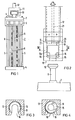
- the fuel assembly 2 in FIG. 1 has a skeleton which has guide tubes 5 connecting a head part 3, a bottom part 4 and head part 3 and bottom part 4. Furthermore, fuel rods 6, which are metal sleeves filled with nuclear fuel, extend from the head part 3 to the base part 4.
- an additional body 7 is screwed, that is detachably attached, which has rods 8 on its side resting on the head part 3, which reach through the head part 3 into the spaces between the fuel rods 6.
- the additional body 7, or at least its rods 8 which reach into the spaces between the fuel rods 6, consist of neutron-absorbing material, for example boron steel.
- the additional body 7 is provided with a handle which has a shaft 9 which is fastened at one end directly to the additional body 7 and at the other end of which there is a cylindrical head 10 projecting beyond the cross section of the shaft 9.
- the handle consisting of the shaft 9 and the head 10 is assigned a coupling part 11 adapted to this handle, which is attached to a holding device, not shown, e.g. a traveling crane or trolley.
- This trolley can be located in a ceiling rail in a storage room for unilluminated fuel elements.
- the coupling part 11 has a hanging on a hollow cylinder 12 base body 13 with an inner bore 14 extending from one end thereof with the hollow cylinder 12 to its other end.
- This inner bore 14 has a shoulder 15 on this other end.
- the base body 13 is provided at this other end with a lateral slot 16 which the Profile of the handle on the additional body 7 is adapted for the fuel assembly 2.
- the shoulder 15 in the bore 14 lies between the end face 17 of the end of the base body 13 opposite the cylinder 12 and the projection 16 a corresponding to the head 10 of the handle on the additional body 7 in the profile of the slot 16, which also extends up to this end face 17.
- a cylindrical sleeve 18 which also has a shoulder 19 on the inside at its end resting on the shoulder 15 and this shoulder laterally with an shoulder 19 extending from the end 19 is also provided longitudinal slot.
- the width of this longitudinal slot is somewhat larger than the diameter of the head 10 of the handle on the additional body 7 for the fuel assembly 2.
- the sleeve 18 At the end with the shoulder 19 opposite the sleeve 18 is screwed on its end face with a tab 20 which is rigidly attached to the end of a rod 21 which is arranged coaxially to the hollow cylinder 12 and to the bore 14 in the hollow cylinder 12. With this rod 21, the sleeve 18 can be rotated about the longitudinal axis of the hollow cylinder 12 and the bore 14 of the base body 13.
- the handle on the additional body 7 is pushed laterally into the bore 14 of the base body 13 of the coupling part 11 when the slots of the base body 13 and the sleeve 18 overlap.
- the sleeve 18 is then rotated about its longitudinal axis with the rod 21, so that it closes the longitudinal slot 16 in the base body 13, as shown in FIG. 4.
- the head 10 of the handle rests on the additional body 7 on the shoulder 19 in the sleeve 18 and this in turn rests on the shoulder 15 of the base body 13 of the coupling part 11.
- a manipulation or storage of a fuel element 2 with the holding device is only possible because of this coupling part if the fuel element 2 is provided with the additional body 7, since otherwise the fuel element 2 cannot be coupled with the coupling part 11 of the holding device.
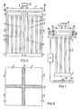
- the rods 8 of the additional body 7 which are made of neutron-absorbing material, can reach into the spaces provided for absorber rods of a nuclear reactor fuel element between the fuel rods 6 of the fuel element 2 if such spaces are provided. 5 and 6, at least one further, e.g. three fuel assemblies 2 are attached.
- the additional body 7 has in this case a rod 8 made of neutron-absorbing material, for. B. boron steel, which has a cross-shaped cross section and which engages between the fuel elements 2 arranged in each case in the corners of a square. This additional body 7 is screwed to all four fuel assemblies 2, for example, that is detachably connected.
- Holding devices e.g. Trolleys in ceiling rails, which are located in a fuel assembly storage room for unilluminated fuel assemblies, have coupling parts 11 which are adapted to the handling of the additional bodies 7. In the fuel assembly storage room, only fuel assemblies that are provided with additional bodies 7 can thus be properly suspended from the trolleys as holding devices.
- nuclear reactor fuel elements provided with additional bodies 7 can already be manipulated with the overhead traveling crane and transferred to the trolleys in the fuel assembly storage space, it is ensured that there are only non-irradiated fuel elements on the trolleys in the fuel assembly storage space, which are provided with neutron-absorbing additional bodies 7, so that in this Fuel element storage space, even if the spacing of the fuel elements from one another is very small, the subcriticality of the geometric arrangement of the fuel elements stored there overall outside of a nuclear reactor is maintained. This also applies if the moderator substance, e.g. Water vapor would enter the fuel storage room.
- moderator substance e.g. Water vapor
- additional elements 7 consisting of control elements which, after the fuel elements 2 have been inserted into a nuclear reactor, are detached from these fuel elements 2, removed from the nuclear reactor and, if appropriate, decontaminated, so that they can be attached to newly manufactured unexposed fuel elements or else for Reattachment to spent fuel elements that are to be unloaded from the nuclear reactor are available.
- spent fuel elements only then e.g. can be manipulated with an overhead crane that has a coupling part 11 adapted to the handle on the additional body 7, if one of the two types of additional body 7 mentioned is attached to them, it is ensured that even when manipulating and storing spent fuel elements 2 outside a nuclear reactor, the subcriticality of the Geometric arrangement is maintained, which forms the entirety of the stored spent fuel elements 2.
- the spent fuel elements can be stored outside of a nuclear reactor at a small distance from one another, without any moderator substance that might be added endangering the subcriticality of the geometric arrangement.
- FIG. 7 An additional security measure to ensure that fuel elements 2 provided with an additional body 7 are manipulated and / or stored is indicated schematically in FIG. 7.
- a fuel assembly 2 which is to be inserted into a shaft 27 of a storage or transport device formed in a boron steel plate 26 for storage or transport purposes outside of a nuclear reactor, can only be locked by the boron steel plate 26 serving as a locking device when the head part 3 of the Fuel element 2 is an additional body 7 projecting over this head part 3, which with its projecting part rests on the boron steel plate 26 after the fuel element has been inserted into the shaft 27.
- Two electrical contacts 28 can be attached to the boron steel plate 26, which the additional body 7 actuates with its part projecting over the head part 3 of the fuel element 2 when it rests properly on the boron steel plate 26 when the fuel element 2 is properly inserted in the shaft 27.
- An electrical alarm device 31 is connected to the contacts 28 and 30, which gives an alarm when the contact 30 is actuated without the contacts 28 being actuated.
- the alarm of the alarm device 31 indicates to the operating personnel that a fuel element 2 may have been inserted in the shaft 27, in which the boron steel plate 26 serving as the locking device did not interact with an additional body 7 and therefore does not have an additional body 7.
- the fuel assembly 2 can thus immediately be removed from the shaft 27 and provided with a neutron-absorbing additional body 7.
- the device according to FIG. 7 can be a storage as well as a transport container for both unilluminated and spent fuel elements. Since unilluminated and irradiated fuel elements are usually transported lying horizontally in a corresponding transport container, it is expedient to provide a corresponding locking device (not shown here) in such a transport container, which can only cooperate with a neutron-absorbing additional body attached to the fuel element, so that the operating personnel cannot lock the fuel assembly inserted into the transport container if this additional body 7 is missing.
Landscapes
- Physics & Mathematics (AREA)
- Engineering & Computer Science (AREA)
- Plasma & Fusion (AREA)
- General Engineering & Computer Science (AREA)
- High Energy & Nuclear Physics (AREA)
- Monitoring And Testing Of Nuclear Reactors (AREA)
Applications Claiming Priority (2)
| Application Number | Priority Date | Filing Date | Title |
|---|---|---|---|
| DE3110582 | 1981-03-18 | ||
| DE3110582A DE3110582C2 (de) | 1981-03-18 | 1981-03-18 | Verfahren zum Manipulieren und/oder Lagern eines Kernreaktorbrennelementes |
Publications (2)
| Publication Number | Publication Date |
|---|---|
| EP0061043A1 EP0061043A1 (de) | 1982-09-29 |
| EP0061043B1 true EP0061043B1 (de) | 1986-11-20 |
Family
ID=6127650
Family Applications (1)
| Application Number | Title | Priority Date | Filing Date |
|---|---|---|---|
| EP82101753A Expired EP0061043B1 (de) | 1981-03-18 | 1982-03-05 | Verfahren zum Manipulieren und/oder Lagern eines ein langgestrecktes Skelett mit Brennstäben aufweisenden Kernreaktorbrennelementes und Kernreaktorbrennelement insbesondere für dieses Verfahren |
Country Status (6)
| Country | Link |
|---|---|
| US (1) | US4904444A (es) |
| EP (1) | EP0061043B1 (es) |
| JP (1) | JPS57184999A (es) |
| BR (1) | BR8201371A (es) |
| DE (1) | DE3110582C2 (es) |
| ES (1) | ES510506A0 (es) |
Families Citing this family (10)
| Publication number | Priority date | Publication date | Assignee | Title |
|---|---|---|---|---|
| FR2544541B1 (fr) * | 1983-04-13 | 1985-12-13 | Transnucleaire | Structure et ensemble de moyens pour le rangement d'elements combustibles nucleaires |
| DE3344525A1 (de) * | 1983-12-09 | 1985-06-20 | Kernforschungsanlage Jülich GmbH, 5170 Jülich | Verfahren zur lagerung abgebrannter brennelemente |
| DE3403780C1 (de) * | 1984-02-03 | 1985-04-18 | Transnuklear Gmbh, 6450 Hanau | Verfahren zur Einhaltung der Unterkritikalitaet von Brennelementen eines Leichtwasserreaktors |
| US4988473A (en) * | 1988-12-08 | 1991-01-29 | Westinghouse Electric Corp. | Self-latching reactivity-reducing device for use in on-site spent fuel assembly storage |
| US4917856A (en) * | 1988-12-08 | 1990-04-17 | Westinghouse Electric Corp. | Self-latching reactivity-reducing device for use in on-site spent fuel assembly storage |
| US6327321B1 (en) * | 1998-11-20 | 2001-12-04 | Framatome Anp, Inc. | Borated aluminum rodlets for use in spent nuclear fuel assemblies |
| DE19916901C1 (de) * | 1999-04-14 | 2000-06-29 | Siemens Ag | Verfahren zum Brennelement-Wechsel in einem Kernkraftwerk |
| DE19947120C2 (de) * | 1999-09-30 | 2002-02-28 | Framatome Anp Gmbh | Verfahren zur Vorbereitung eines Brennelements für die Endlagerung und vorbereitetes Brennelement |
| KR100474340B1 (ko) | 2002-08-02 | 2005-03-10 | 엘지전자 주식회사 | 진공 청소기의 음성제어 장치 및 그 방법 |
| GB2590102A (en) * | 2020-07-24 | 2021-06-23 | Rolls Royce Plc | Refuelling and/or storage neutron-absorbing rods |
Family Cites Families (15)
| Publication number | Priority date | Publication date | Assignee | Title |
|---|---|---|---|---|
| US1648650A (en) * | 1926-03-04 | 1927-11-08 | Frank J Lynch | Elevator |
| GB1131076A (en) * | 1965-04-29 | 1968-10-23 | Atomic Energy Authority Uk | Nuclear reactors |
| US3600277A (en) * | 1968-10-02 | 1971-08-17 | Atomic Energy Commission | Refueling apparatus and method for fast reactors |
| US3768668A (en) * | 1971-12-17 | 1973-10-30 | Combustion Eng | Fuel bundle and control element assembly handling mechanism |
| DE2259669A1 (de) * | 1972-12-06 | 1974-06-12 | Licentia Gmbh | Vorrichtung zur lagerung von in kernreaktoren bestrahlten stabfoermigen teilen, insbesondere von brennelementen, brennelementkaesten und steuerstaeben |
| US3851987A (en) * | 1972-12-29 | 1974-12-03 | Combustion Eng | Eccentric coupling means |
| US4039842A (en) * | 1976-01-08 | 1977-08-02 | Brooks & Perkins, Incorporated | Fuel storage rack |
| US4024406A (en) * | 1976-02-17 | 1977-05-17 | Combustion Engineering, Inc. | Spent fuel storage improvement |
| SE435369B (sv) * | 1977-03-01 | 1984-09-24 | Ernst Haeussler | Lyftorgan for betongelement med forankringsbult. |
| GB1542363A (en) * | 1977-05-25 | 1979-03-14 | Pryamilov J | Nuclear reactors |
| DE2724301C2 (de) * | 1977-05-28 | 1982-05-13 | Thomas R. Crofton Robbins, Md. | Brennelementlager |
| DE2730850A1 (de) * | 1977-07-08 | 1979-01-25 | Nis Nuklear Ingenieur Service | Lagergestell fuer abgebrannte brennelemente |
| JPS5428996A (en) | 1977-08-08 | 1979-03-03 | Mitsubishi Heavy Ind Ltd | Storage method of fuel assembly |
| US4360230A (en) * | 1980-09-12 | 1982-11-23 | The United States Of America As Represented By The United States Department Of Energy | Self locking coupling mechanism for engaging and moving a load |
| JPH05294124A (ja) * | 1992-04-20 | 1993-11-09 | Unisia Jecs Corp | 車両懸架装置 |
-
1981
- 1981-03-18 DE DE3110582A patent/DE3110582C2/de not_active Expired
-
1982
- 1982-03-05 EP EP82101753A patent/EP0061043B1/de not_active Expired
- 1982-03-15 BR BR8201371A patent/BR8201371A/pt unknown
- 1982-03-17 ES ES510506A patent/ES510506A0/es active Granted
- 1982-03-18 JP JP57043690A patent/JPS57184999A/ja active Pending
-
1985
- 1985-09-24 US US06/781,184 patent/US4904444A/en not_active Expired - Fee Related
Also Published As
| Publication number | Publication date |
|---|---|
| US4904444A (en) | 1990-02-27 |
| BR8201371A (pt) | 1983-01-25 |
| JPS57184999A (en) | 1982-11-13 |
| DE3110582C2 (de) | 1986-07-24 |
| ES8402454A1 (es) | 1984-01-16 |
| DE3110582A1 (de) | 1982-10-14 |
| ES510506A0 (es) | 1984-01-16 |
| EP0061043A1 (de) | 1982-09-29 |
Similar Documents
| Publication | Publication Date | Title |
|---|---|---|
| EP0061043B1 (de) | Verfahren zum Manipulieren und/oder Lagern eines ein langgestrecktes Skelett mit Brennstäben aufweisenden Kernreaktorbrennelementes und Kernreaktorbrennelement insbesondere für dieses Verfahren | |
| EP2387487A1 (de) | Robotersystem zum verlegen eines schienenstrangs | |
| DE2500927A1 (de) | Einrichtung zum handhaben radioaktiver kernbrennelemente bei transportvorgaengen | |
| DE2742736A1 (de) | Lagergestell fuer brennelemente | |
| DE2338480C2 (de) | Einrichtung zum Transportieren und Lagern von mit schwach-radioaktiven Abfällen gefüllten Abfallbehältern | |
| DE2238477C3 (de) | Brennstoff anordnung für einen Atomkernreaktor | |
| DE2909793A1 (de) | Montagehilfsgeraet fuer kreuzfoermige steuerstaebe von siedewasserkernreaktoren | |
| DE2528825C2 (de) | Kernreaktoranlage | |
| EP0252375A1 (de) | Verfahren zum Reparieren eines Kernreaktorbrennelementes und Austauschstab für ein solches Verfahren | |
| DE3216855C2 (de) | Behälter zum Lagern neuer Brennelemente | |
| EP0149127A2 (de) | Reparatur- und Montage-Wagen für kerntechnische Anlagen | |
| DE2718305C2 (de) | Brennelementlager | |
| DE3145310A1 (de) | Geraeteaufnahmesystem der medizintechnik | |
| DE2730812C2 (de) | Wagen zum Transportieren von Brennelement-Transportbehältern | |
| DE1564033B1 (de) | Strahlenschutzwand | |
| DE2018495A1 (de) | Verriegelungssystem für Kernreaktoren | |
| DE767003C (de) | Fahrbarer Transformator | |
| DE2264384A1 (de) | Greifer zum gebrauch fuer einen kernreaktor | |
| DE3418312A1 (de) | Transportvorrichtung fuer plattenfoermige bauelemente | |
| EP0088945A1 (de) | Verfahren zum Ent- und Beladen eines Kernreaktors und Steuerelement insbesondere für dieses Verfahren | |
| DE19531499C2 (de) | Vorrichtung für den Transport von normierten Fässern, insbesondere Stahlfässern, die mit radioaktiven Substanzen gefüllt sind | |
| DE2017912C3 (de) | Greifer | |
| Kuehnel et al. | Process for manipulating and/or storing nuclear reactor fuel elements | |
| DE1530272C3 (de) | Radvorleger für Autotransportschienenfahrzeuge | |
| DE2840507A1 (de) | Vorrichtung zur montage von stossdaempfern an brennelement-transportbehaeltern |
Legal Events
| Date | Code | Title | Description |
|---|---|---|---|
| PUAI | Public reference made under article 153(3) epc to a published international application that has entered the european phase |
Free format text: ORIGINAL CODE: 0009012 |
|
| AK | Designated contracting states |
Designated state(s): BE CH FR IT SE |
|
| 17P | Request for examination filed |
Effective date: 19830321 |
|
| GRAA | (expected) grant |
Free format text: ORIGINAL CODE: 0009210 |
|
| AK | Designated contracting states |
Kind code of ref document: B1 Designated state(s): BE CH FR IT LI SE |
|
| ET | Fr: translation filed | ||
| ITF | It: translation for a ep patent filed | ||
| PLBE | No opposition filed within time limit |
Free format text: ORIGINAL CODE: 0009261 |
|
| STAA | Information on the status of an ep patent application or granted ep patent |
Free format text: STATUS: NO OPPOSITION FILED WITHIN TIME LIMIT |
|
| 26N | No opposition filed | ||
| PG25 | Lapsed in a contracting state [announced via postgrant information from national office to epo] |
Ref country code: SE Effective date: 19890306 |
|
| PG25 | Lapsed in a contracting state [announced via postgrant information from national office to epo] |
Ref country code: LI Effective date: 19890331 Ref country code: CH Effective date: 19890331 |
|
| REG | Reference to a national code |
Ref country code: CH Ref legal event code: PL |
|
| PGFP | Annual fee paid to national office [announced via postgrant information from national office to epo] |
Ref country code: BE Payment date: 19910320 Year of fee payment: 10 |
|
| PGFP | Annual fee paid to national office [announced via postgrant information from national office to epo] |
Ref country code: FR Payment date: 19910321 Year of fee payment: 10 |
|
| PG25 | Lapsed in a contracting state [announced via postgrant information from national office to epo] |
Ref country code: BE Effective date: 19920331 |
|
| BERE | Be: lapsed |
Owner name: REAKTOR-BRENNELEMENT UNION GMBH Effective date: 19920331 Owner name: KRAFTWERK UNION AKTIENGESELLSCHAFT Effective date: 19920331 |
|
| PG25 | Lapsed in a contracting state [announced via postgrant information from national office to epo] |
Ref country code: FR Effective date: 19921130 |
|
| REG | Reference to a national code |
Ref country code: FR Ref legal event code: ST |
|
| EUG | Se: european patent has lapsed |
Ref document number: 82101753.0 Effective date: 19900124 |