EP0061066A1 - Rillenzieher - Google Patents
Rillenzieher Download PDFInfo
- Publication number
- EP0061066A1 EP0061066A1 EP82101884A EP82101884A EP0061066A1 EP 0061066 A1 EP0061066 A1 EP 0061066A1 EP 82101884 A EP82101884 A EP 82101884A EP 82101884 A EP82101884 A EP 82101884A EP 0061066 A1 EP0061066 A1 EP 0061066A1
- Authority
- EP
- European Patent Office
- Prior art keywords
- support tube
- groove
- clamping piece
- spring
- joint
- Prior art date
- Legal status (The legal status is an assumption and is not a legal conclusion. Google has not performed a legal analysis and makes no representation as to the accuracy of the status listed.)
- Granted
Links
Images

Classifications
-
- A—HUMAN NECESSITIES
- A01—AGRICULTURE; FORESTRY; ANIMAL HUSBANDRY; HUNTING; TRAPPING; FISHING
- A01C—PLANTING; SOWING; FERTILISING
- A01C5/00—Making or covering furrows or holes for sowing, planting or manuring
- A01C5/02—Hand tools for making holes for sowing, planting or manuring
-
- F—MECHANICAL ENGINEERING; LIGHTING; HEATING; WEAPONS; BLASTING
- F16—ENGINEERING ELEMENTS AND UNITS; GENERAL MEASURES FOR PRODUCING AND MAINTAINING EFFECTIVE FUNCTIONING OF MACHINES OR INSTALLATIONS; THERMAL INSULATION IN GENERAL
- F16B—DEVICES FOR FASTENING OR SECURING CONSTRUCTIONAL ELEMENTS OR MACHINE PARTS TOGETHER, e.g. NAILS, BOLTS, CIRCLIPS, CLAMPS, CLIPS OR WEDGES; JOINTS OR JOINTING
- F16B7/00—Connections of rods or tubes, e.g. of non-circular section, mutually, including resilient connections
- F16B7/04—Clamping or clipping connections
- F16B7/044—Clamping or clipping connections for rods or tubes being in angled relationship
- F16B7/048—Clamping or clipping connections for rods or tubes being in angled relationship for rods or for tubes without using the innerside thereof
Definitions
- the invention relates to a groove puller of the type specified in the preamble of claim 1.
- the shares are provided in the head part with threaded holes through which the locking screws can be braced against the support tube.
- This type of screw attachment requires a considerable amount of work and time if the coulters on the support tube are to be adjusted or removed from it.
- a further disadvantage of this type of fastening is that the screw thread connection can become clogged by dirt or rust, so that loosening or fastening the shares requires considerable effort.
- the invention is therefore based on the object of improving a groove puller of the type according to the preamble of claim 1 in such a way that, with reliable fixing of the shares on the support tube, easy displacement and installation without screw fastening is ensured.
- This measure makes it possible to incline the handle relative to the support tube in such a way that the operator can walk past the bed laterally and can easily pull the grooves in the longitudinal direction of the bed.
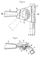
- FIG. 1 has a support tube 10 with a square cross section, to which a hinge plate 12 is welded, which is connected to the device connection sleeve 16 used for the handle 14 via a swivel joint, which is shown in FIGS. 3 and 4 in detail is shown.
- the carrier tube 10 has notches at predetermined uniform intervals, into which engagement means of the shares can engage, one of which is shown in partial section in FIG. 2.
- This coulter 20, which consists of sheet metal, has a head part in the two side walls 22 (only one of which is shown in FIG. 2, namely the rear wall), which has a V-cut 24 that is matched to the cross section of the tube 10 exhibit.
- each coulter 20 has an insertion hole 28 in the front wall 26, which is produced in one piece with the side walls 22, and a guide hole 32 aligned axially thereon in the rear wall 30.
- a clamping piece 34 made of plastic projects outwards with a handle push button 36 through the insertion hole 28 of the front wall 26.
- a shoulder 38 of the elemm piece 34 projects through a recess in the rear wall 30 and is displaceable therein.
- the handle push button 36 has a coaxial guide hole 40 for a guide pin 42 which protrudes with its end into the guide hole 32.
- a hole widening 46 has a compression coil spring 48 wrapped around the guide pin 42.
- the clamping piece 34 also has a V-shaped clamping profile 50, the apex of which is penetrated by a cylindrical notch pin 52.
- This clamping profile 50 is pressed by the spring 48 against the carrier tube 10, the notch pin 52 expediently being located in one of the notches 18.
- the handle push button 36 is pressed in against the action of the spring 44, so that the V-shaped clamping profile 50 is lifted off the carrier tube 10. Now the coulter 20 can be moved on the carrier tube 10 or removed from it.
- the clamping piece can be inserted in a simple manner into the head part made of bent sheet metal, the clamping piece 34 being fixed after the end of the guide pin 42 engaging in the guide hole 32 and being displaced in the direction of the axis of the guide pin 42 thereon can be.
- the angled hinge plate 12 is fixed by spot welding in the middle of the support tube 10.
- a nut 56 is pressed or welded into a bore 54 of the joint plate 12.
- a joint holder 58 connected to the device connecting sleeve 16 lies above the joint plate 12 and has an insertion hole through which a screw bolt 60 which can be screwed into the nut 56 projects, the head 62 of which is designed as a handle and with a collar 64 abuts the hinge bracket 58 from above.
- the articulated holder 58 has inwardly embossed latching gaps which are matched to latching noses 66 of the articulated plate 12 and lie on a circular arc which is concentric with the articulated axis.
- the screw bolt 60 is secured against unscrewing by a fastening element 68.
- a plate spring 70 is inserted between the hinge plate and the hinge bracket.
- the handle By means of the joint which can be fixed by means of the adjusting screw 60, 62, the handle can be adjusted in different angular positions relative to the carrier tube 10, three positions of which are indicated in FIG. 3. If the screw 60, 62 is loosened, the plate spring 70 presses off the joint holder 58 from the joint plate 12, so that the detents 66 disengage. By turning the joint to the left or right, the angle between the device connection and the device is changed. When the desired setting is reached, the joint is locked by tightening the screw. In this way, grooves can be conveniently drawn from a lateral path of the bed without it being necessary to enter the bed itself.
Landscapes
- Life Sciences & Earth Sciences (AREA)
- Engineering & Computer Science (AREA)
- General Engineering & Computer Science (AREA)
- Soil Sciences (AREA)
- Mechanical Engineering (AREA)
- Environmental Sciences (AREA)
- Clamps And Clips (AREA)
- Quick-Acting Or Multi-Walled Pipe Joints (AREA)
- Mutual Connection Of Rods And Tubes (AREA)
Abstract
Description
- Die Erfindung bezieht sich auf einen Rillenzieher der im Oberbegriff des Anspruchs 1 angegebenen Gattung. Bei einem bekannten Rillenzieher dieser Bauart sind die Scharen im Kopfteil mit Gewindelöchern versehen, durch die Feststellschrauben gegen das Trägerrohr verspannt werden können. Diese Art der Schraubbefestigung erfordert einen erheblichen Arbeits- und Zeitaufwand, wenn die Scharen auf dem Trägerrohr verstellt oder von diesem abgenommen werden sollen. Nachteilig an dieser Art der Befestigung ist weiter, daß sich die Schraubgewindeverbindung durch Schmutz oder Rost zusetzen kann, so daß ein Lösen oder auch eine Befestigung der Scharen einen erheblichen Kraftaufwand erfordert.
- Der Erfindung liegt daher die Aufgabe zugrunde, einen Rillenzieher der Gattung gemäß Oberbegriff des Anspruchs 1 derart zu verbessern, daß bei zuverlässiger Fixierung der Scharen am Trägerrohr eine leichte Verschiebbarkeit und Montage ohne Schraubbefestigung gewährleistet ist.
- Gelöst wird die gestellte Aufgabe durch die im Kennzeichnungsteil des Anspruchs 1 angegebenen Merkmale. Weitere zweckmäßige Ausgestaltungen der Scharbefestigung ergeben sich aus den Unteransprüchen 2 bis 7. Nachteilig an den bisher bekannten Rillenziehern war außerdem die starre Befestigung zwischen Stieltülle und Trägerrohr. Hierdurch bedingt mußte die den Rillenzieher führende Person über das Beet schreiten, in das die Rillen gezogen werden sollten. Diese Nachteile bekannter Rillenzieher werden gemäß der Erfindung vermieden durch die Merkmale des Anspruchs 8.
- Durch diese Maßnahme wird es möglich, den Stiel gegenüber dem Trägerrohr derart schräg zu stellen, daß die Bedienungsperson seitlich am Beet vorbeischreiten und die Rillen bequem in Längsrichtung des Beetes ziehen kann.
- Weitere zweckmäßige Ausgestaltungen des Schwenkgelenkes ergeben sich aus den Unteransprüchen 9 bis 12.
- Nachstehend wird ein Ausführungsbeispiel der Erfindung anhand der Zeichnung beschrieben. In der Zeichnung zeigen:
- Fig. 1 eine Ansicht des Rillenziehers (ohne Scharen),
- Fig. 2 eine teilweise geschnittene Ansicht einer auf dem Trägerrohr sitzenden Schar mit Klemmvorrichtung,
- Fig. 3 im größeren Maßstab eine Ansicht des in Fig. 1 mit III gekennzeichneten Teils des Rillenziehers,
- Fig. 4 einen Schnitt nach der Linie IV-IV gemäß Fig. 3.
- Der Rillenzieher gemäß Fig. 1 weist ein Trägerrohr 10 mit quadratischem Querschnitt auf, an welchem eine Gelenkplatte 12 verschweißt ist, die mit der zum Einsatz des Stieles 14 dienenden Geräteanschlußtülle 16 über ein Drehgelenk verbunden ist, welches in den Fig. 3 und 4 im einzelnen dargestellt ist. Das Trägerrohr 10 weist in vorbestimmten gleichmäßigen Abständen Kerben auf, in die Rastmittel der Scharen eingreifen können, von denen eine in Fig. 2 im Teilschnitt dargestellt ist. Diese Schar 20, die aus Blech besteht, weist ein Kopfteil in den zwei Seitenwänden 22 (von denen in Fig. 2 nur eine, nämlich die hintere Wand, dargestellt ist) auf, die einen auf den Querschnitt des Rohres 10 abgestimmten V-Einschnitt 24 aufweisen. Der Kopfteil jeder Schar 20 weist in der einstückig mit den Seitenwänden 22 hergestellten Vorderwand 26 ein Einsatzloch 28 und axial hierauf ausgerichtet in der Rückwand 30 ein Führungsloch 32 auf. Ein aus Kunststoff bestehendes Klemmstück 34 steht mit einem Handhabedruckknopf 36 durch das Einsatzloch 28 der Vorderwand 26 nach außen vor. Ein Ansatz 38 des Elemmstückes 34 steht durch eine Ausnehmung der Rückwand 30 vor und ist in dieser verschiebbar. Der Handhabedruckknopf 36 weist ein koaxiales Führungsloch 40 für einen Führungsbolzen 42 auf, der mit seinem Ende in das Führungsloch 32 einsteht. Zwischen einem auf dem Führungsbolzen 42 festgelegten Federteller 44 und einem Ringbund einer Locherweiterung 46 ist eine den Führungsbolzen 42 umschlingende Druckschraubenfeder 48 angeordnet.
- Das Klemmstück 34 weist ferner ein V-förmiges Klemmprofil 50 auf, dessen Scheitel von einem Zylinderkerbstift 52 durchsetzt ist. Dieses Klemmprofil 50 wird durch die Feder 48 gegen das Trägerrohr 10 gepreßt, wobei der Kerbstift 52 zweckmäßigerweise in jeweils einer der Kerben 18 zu liegen kommt.
- Zum Lösen der Klemmvorrichtung wird der Handhabe- druckknopf 36 entgegen der Wirkung der Feder 44 eingedrückt, so daß das V-förmige Klemmprofil 50 von dem Trägerrohr 10 abgehoben wird. Nunmehr kann die Schar 20 auf dem Trägerrohr 10 beliebig verschoben oder von diesem abgenommen werden.
- Bei der Montage kann das Klemmstück auf einfache Weise in das aus abgebogenem Blech bestehende Kopfteil von innen her eingefügt werden, wobei nach Eingreifen des Endes des Führungsbolzens 42 in das Führungsloch 32 das Klemmstück 34 fixiert ist und in Richtung der Achse des Führungsbolzens 42 auf diesem verschoben werden kann.
- Die abgewinkelte Gelenkplatte 12 ist durch Punktverschweißung in der Mitte des Trägerrohres 10 festgelegt. In eine Bohrung 54 der Gelenkplatte 12 ist eine Mutter 56 eingepreßt oder eingeschweißt. Ein mit der Geräteanschlußtülle 16 verbundener Gelenkhalter 58 liegt über der Gelenkplatte 12 und weist ein Einsatzloch auf, durch das ein in die Mutter 56 einschraubbarer Schraubbolzen 60 hindurchsteht, dessen Kopf 62 als Handhabe ausgebildet ist und mit einem Spannbund 64 dem Gelenkhalter 58 von oben her anliegt.
- Der Gelenkhalter 58 besitzt nach innen geprägte Rastlücken, die auf Rastnasen 66 der Gelenkplatte 12 abgestimmt sind und auf einem zur Gelenkachse konzentrischen Kreisbogen liegen. Der Schraubbolzen 60 ist durch ein Befestigungselement 68 gegen Herausdrehen gesichert. Zwischen der Gelenkplatte und dem Gelenkhalter ist eine Tellerfeder 70 eingefügt.
- Durch das mittels der Stellschraube 60, 62 festlegbare Gelenk läßt sich der Stiel gegenüber dem Trägerrohr 10 in verschiedenen Winkelstellungen einstellen, von denen drei Stellungen in Fig. 3 angedeutet sind. Wird die Schraube 60, 62 gelöst, so drückt die Tellerfeder 70 den Gelenkhalter 58 von der Gelenkplatte 12 ab, so daß die Rastnasen 66 außer Eingriff kommen. Durch Drehen des Gelenks nach links oder rechts wird der Winkel zwischen Geräteanschluß und Gerät verändert. Wenn die gewünschte Einstellung erreicht ist, wird durch Festdrehen der Schraube das Gelenk arretiert. Auf diese Weise können von einem seitlichen Weg des Beetes her bequem Rillen gezogen werden, ohne daß es notwendig wäre, das Beet selbst zu betreten.
Claims (10)
Applications Claiming Priority (2)
| Application Number | Priority Date | Filing Date | Title |
|---|---|---|---|
| DE8108616U | 1981-03-24 | ||
| DE8108616 | 1981-03-24 |
Publications (2)
| Publication Number | Publication Date |
|---|---|
| EP0061066A1 true EP0061066A1 (de) | 1982-09-29 |
| EP0061066B1 EP0061066B1 (de) | 1985-06-26 |
Family
ID=6726017
Family Applications (1)
| Application Number | Title | Priority Date | Filing Date |
|---|---|---|---|
| EP82101884A Expired EP0061066B1 (de) | 1981-03-24 | 1982-03-09 | Rillenzieher |
Country Status (2)
| Country | Link |
|---|---|
| US (1) | US4461357A (de) |
| EP (1) | EP0061066B1 (de) |
Cited By (2)
| Publication number | Priority date | Publication date | Assignee | Title |
|---|---|---|---|---|
| US4633791A (en) * | 1984-08-31 | 1987-01-06 | Deere & Company | Opener assembly including a compact, arc-shaped opener |
| US20220240437A1 (en) * | 2019-07-04 | 2022-08-04 | Väderstad Holding Ab | Furrow Opener, Row Unit, Agricultural Implement and Method of Operating a Furrow Opener |
Families Citing this family (1)
| Publication number | Priority date | Publication date | Assignee | Title |
|---|---|---|---|---|
| US6698178B1 (en) * | 2000-12-01 | 2004-03-02 | David Huffman | Sand trap rake and storage apparatus |
Citations (3)
| Publication number | Priority date | Publication date | Assignee | Title |
|---|---|---|---|---|
| FR589519A (fr) * | 1924-09-16 | 1925-05-30 | Appareil rayonneur | |
| DE455768C (de) * | 1927-07-28 | 1928-02-08 | Hermann Petersen | Handgeraet zum Ziehen von Furchen, bei welchem durch Verschieben der Flugschare der jeweilige Furchenabstand geregelt wird |
| DE832349C (de) * | 1948-11-30 | 1952-03-27 | Juenemann G M B H | Rillen- und Furchenzieher |
Family Cites Families (5)
| Publication number | Priority date | Publication date | Assignee | Title |
|---|---|---|---|---|
| CA465222A (en) * | 1950-05-23 | William Bean Arthur | Tool bar assembly for agricultural purposes | |
| US645702A (en) * | 1899-09-21 | 1900-03-20 | Louis Arthur Arlaud | Land-marker. |
| US1548906A (en) * | 1924-10-18 | 1925-08-11 | Schroer William | Rake |
| US1768080A (en) * | 1927-12-27 | 1930-06-24 | Kurihara Yasaku | Lawn rake |
| US2804109A (en) * | 1956-02-28 | 1957-08-27 | John A Fatica | Combination axe and adz with adjustable blade |
-
1982
- 1982-03-09 EP EP82101884A patent/EP0061066B1/de not_active Expired
- 1982-03-19 US US06/359,782 patent/US4461357A/en not_active Expired - Fee Related
Patent Citations (3)
| Publication number | Priority date | Publication date | Assignee | Title |
|---|---|---|---|---|
| FR589519A (fr) * | 1924-09-16 | 1925-05-30 | Appareil rayonneur | |
| DE455768C (de) * | 1927-07-28 | 1928-02-08 | Hermann Petersen | Handgeraet zum Ziehen von Furchen, bei welchem durch Verschieben der Flugschare der jeweilige Furchenabstand geregelt wird |
| DE832349C (de) * | 1948-11-30 | 1952-03-27 | Juenemann G M B H | Rillen- und Furchenzieher |
Cited By (3)
| Publication number | Priority date | Publication date | Assignee | Title |
|---|---|---|---|---|
| US4633791A (en) * | 1984-08-31 | 1987-01-06 | Deere & Company | Opener assembly including a compact, arc-shaped opener |
| US20220240437A1 (en) * | 2019-07-04 | 2022-08-04 | Väderstad Holding Ab | Furrow Opener, Row Unit, Agricultural Implement and Method of Operating a Furrow Opener |
| US12336450B2 (en) * | 2019-07-04 | 2025-06-24 | Väderstad Holding Ab | Furrow opener, row unit, agricultural implement and method of operating a furrow opener |
Also Published As
| Publication number | Publication date |
|---|---|
| EP0061066B1 (de) | 1985-06-26 |
| US4461357A (en) | 1984-07-24 |
Similar Documents
| Publication | Publication Date | Title |
|---|---|---|
| EP0918655B1 (de) | Kupplungsanordnung für ein fahrzeug | |
| DE9211739U1 (de) | Walzenförmiger Schneidkörper für eine Schrämmaschine | |
| DE10231997A1 (de) | Einstellbares Handwerkzeug mit zwei Funktionen | |
| EP1156256A2 (de) | Spannring | |
| DE4416939A1 (de) | Spritzpistole | |
| DE1627021B2 (de) | Bohrstange | |
| DE69936954T2 (de) | Klemmglied für mindestens einen Stützstift für Förderband-Bauteile | |
| DE4327118A1 (de) | Kombiniertes Umschnürungs- und Abschneidewerkzeug | |
| DE3445885A1 (de) | Scharnier | |
| DE3130703C2 (de) | Stielbefestigungskupplung, insbesondere für Haus- und Gartengeräte | |
| DE3000470C2 (de) | Anhängerdeichsel | |
| EP0061066A1 (de) | Rillenzieher | |
| DE2256125C3 (de) | Zusammenlegbares Stativ | |
| DE19746669B4 (de) | Bolzenschweißvorrichtung | |
| DE19951149C2 (de) | Vorrichtung zum Befestigen und Spannen eines Seiles | |
| DE19617821A1 (de) | Kombinationswaage | |
| DE8108616U1 (de) | Rillenzieher zum Ziehen von Saatrillen auf Beeten | |
| DE2225747A1 (de) | Werkzeughalter | |
| EP0686341B1 (de) | Scheibensäschar | |
| DE10102704C1 (de) | Vorrichtung zum Einschrauben von Befestigungselementen | |
| DE3830426C2 (de) | ||
| DE2357284C3 (de) | Skibindung mit einem Zugorgan und einem mit diesem über ein Einstellglied verbundenen Spannhebel | |
| DD249172A5 (de) | Landwirtschaftliches geraet mit einem rahmenteil und einem werkzeugrahmen | |
| DE3226210A1 (de) | Gartengeraet zum jaeten von unkraut | |
| DE9103333U1 (de) | Vorrichtung zur Befestigung von sanitärkeramischen Gegenständen |
Legal Events
| Date | Code | Title | Description |
|---|---|---|---|
| PUAI | Public reference made under article 153(3) epc to a published international application that has entered the european phase |
Free format text: ORIGINAL CODE: 0009012 |
|
| AK | Designated contracting states |
Designated state(s): BE FR NL |
|
| 17P | Request for examination filed |
Effective date: 19830321 |
|
| GRAA | (expected) grant |
Free format text: ORIGINAL CODE: 0009210 |
|
| AK | Designated contracting states |
Designated state(s): BE FR NL |
|
| ET | Fr: translation filed | ||
| PLBE | No opposition filed within time limit |
Free format text: ORIGINAL CODE: 0009261 |
|
| STAA | Information on the status of an ep patent application or granted ep patent |
Free format text: STATUS: NO OPPOSITION FILED WITHIN TIME LIMIT |
|
| 26N | No opposition filed | ||
| PGFP | Annual fee paid to national office [announced via postgrant information from national office to epo] |
Ref country code: BE Payment date: 19900314 Year of fee payment: 9 |
|
| PG25 | Lapsed in a contracting state [announced via postgrant information from national office to epo] |
Ref country code: BE Effective date: 19910331 |
|
| PGFP | Annual fee paid to national office [announced via postgrant information from national office to epo] |
Ref country code: NL Payment date: 19910331 Year of fee payment: 10 |
|
| BERE | Be: lapsed |
Owner name: WOLF-GERATE G.M.B.H. Effective date: 19910331 |
|
| PG25 | Lapsed in a contracting state [announced via postgrant information from national office to epo] |
Ref country code: NL Effective date: 19921001 |
|
| NLV4 | Nl: lapsed or anulled due to non-payment of the annual fee | ||
| PGFP | Annual fee paid to national office [announced via postgrant information from national office to epo] |
Ref country code: FR Payment date: 19940218 Year of fee payment: 13 |
|
| PG25 | Lapsed in a contracting state [announced via postgrant information from national office to epo] |
Ref country code: FR Free format text: LAPSE BECAUSE OF NON-PAYMENT OF DUE FEES Effective date: 19951130 |
|
| REG | Reference to a national code |
Ref country code: FR Ref legal event code: ST |