EP0061068A2 - Verfahren zum Betrieb einer Brennstoffzellenanlage - Google Patents
Verfahren zum Betrieb einer Brennstoffzellenanlage Download PDFInfo
- Publication number
- EP0061068A2 EP0061068A2 EP82101901A EP82101901A EP0061068A2 EP 0061068 A2 EP0061068 A2 EP 0061068A2 EP 82101901 A EP82101901 A EP 82101901A EP 82101901 A EP82101901 A EP 82101901A EP 0061068 A2 EP0061068 A2 EP 0061068A2
- Authority
- EP
- European Patent Office
- Prior art keywords
- pressure
- accordance
- fuel
- steam
- fuel cell
- Prior art date
- Legal status (The legal status is an assumption and is not a legal conclusion. Google has not performed a legal analysis and makes no representation as to the accuracy of the status listed.)
- Granted
Links
Images
Classifications
-
- H—ELECTRICITY
- H01—ELECTRIC ELEMENTS
- H01M—PROCESSES OR MEANS, e.g. BATTERIES, FOR THE DIRECT CONVERSION OF CHEMICAL ENERGY INTO ELECTRICAL ENERGY
- H01M8/00—Fuel cells; Manufacture thereof
- H01M8/04—Auxiliary arrangements, e.g. for control of pressure or for circulation of fluids
- H01M8/04082—Arrangements for control of reactant parameters, e.g. pressure or concentration
- H01M8/04089—Arrangements for control of reactant parameters, e.g. pressure or concentration of gaseous reactants
-
- H—ELECTRICITY
- H01—ELECTRIC ELEMENTS
- H01M—PROCESSES OR MEANS, e.g. BATTERIES, FOR THE DIRECT CONVERSION OF CHEMICAL ENERGY INTO ELECTRICAL ENERGY
- H01M8/00—Fuel cells; Manufacture thereof
- H01M8/06—Combination of fuel cells with means for production of reactants or for treatment of residues
- H01M8/0606—Combination of fuel cells with means for production of reactants or for treatment of residues with means for production of gaseous reactants
- H01M8/0612—Combination of fuel cells with means for production of reactants or for treatment of residues with means for production of gaseous reactants from carbon-containing material
-
- Y—GENERAL TAGGING OF NEW TECHNOLOGICAL DEVELOPMENTS; GENERAL TAGGING OF CROSS-SECTIONAL TECHNOLOGIES SPANNING OVER SEVERAL SECTIONS OF THE IPC; TECHNICAL SUBJECTS COVERED BY FORMER USPC CROSS-REFERENCE ART COLLECTIONS [XRACs] AND DIGESTS
- Y02—TECHNOLOGIES OR APPLICATIONS FOR MITIGATION OR ADAPTATION AGAINST CLIMATE CHANGE
- Y02E—REDUCTION OF GREENHOUSE GAS [GHG] EMISSIONS, RELATED TO ENERGY GENERATION, TRANSMISSION OR DISTRIBUTION
- Y02E60/00—Enabling technologies; Technologies with a potential or indirect contribution to GHG emissions mitigation
- Y02E60/30—Hydrogen technology
- Y02E60/50—Fuel cells
Definitions
- This invention relates to fuel cell systems, and in particular, to apparatus and method for operating such systems.
- Our European application 82 100 369.6 discloses a system which enables the production of high pressure steam without increased fuel cell temperature through the use of an auxilliary heat exchanger which responds to the exhaust oxidant gas and to a higher temperature gas derived elsewhere in the system and which through heat exchange increases the exhaust oxidant gas temperature.
- the oxidant gas at the higher temperature is then applied to a steam generator for generating steam at the pressure necessary to produce fuel process gas at the required high pressure (e.g., at a pressure in the range of about 30 to 200 psia).
- the above and other objectives are realized in a fuel cell system wherein the fuel and oxidant gases are supplied to the respective anode and cathode sections of the system fuel cell at different pressures, the pressure of the fuel gas being lower than that of the oxidant gas which is maintained high to promote fuel cell efficiency.
- a lower pressure fuel gas permits the use of lower pressure steam in the reforming reaction.
- the temperature of the exhaust oxidant gas used to produce the steam can thus be lower, thereby enabling operation of the fuel cell at a lower temperature and, extending fuel cell life.
- the reformation reaction can be at a lower pressure, reducing the equilibrium methane content and, therefore, increasing the system efficiency.
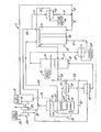
- the fuel cell system 1 includes a fuel cell 10.
- the cell 10 is assumed to be a phosphoric acid 'cell, but the principles of the invention extend to other fuel cell types, such as, for example, molten carbonate cells and solid oxide cells.
- An anode section 2 and a cathode section 3 communicate with an electrolyte, matrix 50 and receive fuel process gas and oxidant process gas from fuel and oxidant gas input conduits 5 and 6 respectively
- the oxidant gas is derived from oxidant source conduits 7 and 8, the first one of which 7 is fed a portion of the exhausted oxidant gas coupled to an exhaust conduit 9 and the second one of which 8 receives oxidant gas from an oxidant supply 11 after being pressurized by a compressor 12.
- the exhausted oxidant gas from the conduit 9 prior to being coupled to the conduit 7 is passed through a heat exchanger 13 situated between the conduits and to which is also supplied water from a supply 14.
- the output from exchanger 13 comprises steam which is to be used in processing of fresh supply fuel to form the fuel process gas. More particularly, the generated steam'is coupled through a conduit 15 to the high temperature section 16 of a combined high temperature - low temperature shift converter 17.
- the output steam at a higher temperature now in a conduit 18, is combined in a common conduit 21 with pressurized fresh supply fuel received from a conduit 22.
- Conduit 22 communicates with a .supply of fuel 23 which has been pressurized in a compressor.24 and preheated in a heat exchanger 25.
- the combined fuel and steam in the line 21 after being heated in a heat exchanger 26 is coupled to a fuel processor or reformer 27, the output of which is fuel process gas whose pressure is dependent on that of the steam.
- the fuel process gas from the reformer 27 is passed through heat exchangers 26 and 25 and the high and low temperature sections 16 and 41 of the converter 17. Water from a supply 42 feeding the low temperature section 41 as well as the other constituents being passed through the elements 26, 25 and 16 cool the fuel process gas.
- the cooled gas is then further cooled to the desired fuel cell input temperature by a further heat exchanger 28 which receives water from the supply 2Q.
- the reformer 27 is provided with reaction heat from a burner 31 to which is supplied a portion of the fuel in the conduit 22 via conduit 32, a portion of the fresh compressed oxidant supply via conduit 33, and the exhausted fuel process gas, via the conduit 34.
- the latter gases are preheated in respective heat exchangers 36 and 37 to which is also supplied the heated gas of the burner 31. Thereafter, this gas is coupled to a common conduit 38 along with exhausted oxidant gas in a conduit 39 and the combined gases passed through a turboexpander 45 for subsequent exhaust out of the system.
- the pressures of the fuel process gas in the conduit 5 and the oxidant process gas in the conduit 6 are maintained at substantially the same value (i.e., in normal practice, these pressures might differ by less than about 1 psi).
- the quantity and temperature of the exhausted oxidant gas coupled to the exchanger 13 must be sufficient to provide steam of the required quantity and pressure.
- the pressure of the steam from the exchanger 13 must also be increased so as to result in an increase in the fuel process gas pressure provided through the reforming reaction.
- Increased steam pressure is brought about by increasing the quantity and/or temperature of the exhausted oxidant gas. While increases of this nature can be tolerated to some degree, as required pressures exceed about 30 psia, the quantity and/or temperature required of the exhausted oxidant gas begin to counteract the added benefits of operating at the higher pressures.
- the benefits of higher pressure fuel cell operation are realized without the detrimental effects which result from the use of exhausted oxidant gas of increased quantity and/or temperature.
- This is achieved by operating the present system with the oxidant gas pressure at the desired higher pressure for obtaining the benefits of high pressure operation and the fuel process gas at a lesser pressure than practiced in conventional cells and, preferably, at a pressure for which the quantity and temperature constraints required of the cell exhausted oxidant gas for process gas generation can be met without otherwise appreciably detracting from system performance.
- the pressure p l of the oxidant gas from the compressor 12 and coupled to the conduit 6 via the conduit 8 is at a first pressure value
- the pressure p 2 of the fuel process gas in the conduit 5 is at a lower pressure value
- the value of the pressure p 1 is preferably made as high as possible and its maximum value is determined generally by the operation of compressor 12, which, in turn, depends on the energy derived from exhaust gas stream 38 upon expansion, this energy being used to run the turbocompressor 12. Typically, a preferable range for this value might be 30 to 200 psia. Furthermore, the difference between the pressures p l and p 2 should be compatible with pressure differentials sustainable by the electrolyte carrying matrix 50 separating the anode and cathode sections 2 and 3. In accordance with the invention, pressure differentials in the range of 10 to 50 psi are contemplated.
- a matrix for sustaining pressure differentials in the above range for phosphoric acid fuel cells might comprise a layer of silicon carbide and a layer of carbon, the carbon containing layer having a particle size of less than approximately 500 angstroms and a surface area of greater than approximately 100 square meters per gram.
- the anode and cathode section hydrophobic electrodes might comprise catalysts on carbon supports, the carbon of these supports having the same particle size and surface area as the carbon containing layer of'the matrix.
- the quantity of steam produced at this pressure from the exhausted oxidant gas at the cell temperature of 350°F can ba calculated from the following equation: Where ⁇ H is the latent heat of steam Cp is the heat capacity of oxidant gas to is the initial temperature of oxidant gas t p is a temperature equal to the steam saturation temperature t s which is dependent upon the steam pressure plus a small differential or pinch temperature.
- the cell temperature in the equal pressure case would have to be increased to 383°F in order to obtain the same quantity of steam. At this 33°F higher temperature, the cell life could be substantially reduced.
- the operation-of the anode at 20 psi lower pressure than the cathode will result in a substantially improved fuel cell life, because of lower operating temperature. The benefits of the present system are therefore apparent.
- the ability to operate the reformer at lower pressures with the present system has the further benefit of providing a lower equilibrium methane content in the resultant fuel produced by the reformer for the fuel cell 10. Since methane generally acts as an inert gas in the fuel cell-reaction; but has a high heating value, a reduction in methane content results in a more efficient operation of the fuel cell. Also, the lower pressure reduces the tendency in the reformer of producing carbon by the reaction 2CO C + C 0 2 Finally, in the fuel cell 10 itself, lower pressures in the fuel gas are beneficial from a CO poisioning point of view, since poisioning depends on CO partial pressures.
Landscapes
- Life Sciences & Earth Sciences (AREA)
- Engineering & Computer Science (AREA)
- Manufacturing & Machinery (AREA)
- Sustainable Development (AREA)
- Sustainable Energy (AREA)
- Chemical & Material Sciences (AREA)
- Chemical Kinetics & Catalysis (AREA)
- Electrochemistry (AREA)
- General Chemical & Material Sciences (AREA)
- Fuel Cell (AREA)
Applications Claiming Priority (2)
| Application Number | Priority Date | Filing Date | Title |
|---|---|---|---|
| US06/242,671 US4362788A (en) | 1981-03-11 | 1981-03-11 | Fuel cell system with anode and cathodes operating at different pressures |
| US242671 | 1981-03-11 |
Publications (3)
| Publication Number | Publication Date |
|---|---|
| EP0061068A2 true EP0061068A2 (de) | 1982-09-29 |
| EP0061068A3 EP0061068A3 (en) | 1983-03-23 |
| EP0061068B1 EP0061068B1 (de) | 1986-10-15 |
Family
ID=22915735
Family Applications (1)
| Application Number | Title | Priority Date | Filing Date |
|---|---|---|---|
| EP82101901A Expired EP0061068B1 (de) | 1981-03-11 | 1982-03-10 | Verfahren zum Betrieb einer Brennstoffzellenanlage |
Country Status (7)
| Country | Link |
|---|---|
| US (1) | US4362788A (de) |
| EP (1) | EP0061068B1 (de) |
| JP (1) | JPS57158964A (de) |
| BR (1) | BR8201296A (de) |
| CA (1) | CA1161110A (de) |
| DE (1) | DE3273869D1 (de) |
| MX (1) | MX157807A (de) |
Cited By (2)
| Publication number | Priority date | Publication date | Assignee | Title |
|---|---|---|---|---|
| EP0374636A1 (de) * | 1988-12-20 | 1990-06-27 | Asea Brown Boveri Ag | Verfahren zur Umwandlung von in einem Stoff als chemisches Potential vorliegender Energie in elektrische Energie basierend auf einem elektrochemischen Hochtemperaturprozess |
| EP1836741A4 (de) * | 2004-12-29 | 2009-04-08 | Utc Power Corp | Brennstoffzellenbaugruppe mit betriebstemperaturen für verlängerte lebensdauer |
Families Citing this family (15)
| Publication number | Priority date | Publication date | Assignee | Title |
|---|---|---|---|---|
| US4781241A (en) * | 1987-08-27 | 1988-11-01 | International Fuel Cells Corporation | Heat exchanger for fuel cell power plant reformer |
| DE19822691A1 (de) * | 1998-05-20 | 1999-11-25 | Volkswagen Ag | Brennstoffzellensystem und Verfahren zum Erzeugen elektrischer Energie mittels eines Brennstoffzellensystems |
| DE19822689A1 (de) * | 1998-05-20 | 1999-11-25 | Volkswagen Ag | Brennstoffzellensystem und Verfahren zum Erzeugen elektrischer Energie mittels eines Brennstoffzellensystems |
| US6218038B1 (en) | 1999-08-24 | 2001-04-17 | Plug Power, Inc. | Regulating a flow through a fuel cell |
| DE19952384A1 (de) * | 1999-10-30 | 2001-05-17 | Forschungszentrum Juelich Gmbh | Optimierung der Betriebsparameter eines Direkt-Methanol-Brennstoffzellensystems |
| JP2002015758A (ja) * | 2000-06-30 | 2002-01-18 | Honda Motor Co Ltd | リン酸型燃料電池の運転方法 |
| US20050121315A1 (en) * | 2003-12-05 | 2005-06-09 | Baltrucki Justin D. | System for generating hydrogen and method thereof |
| AU2001275997A1 (en) | 2000-07-20 | 2002-02-05 | Proton Energy Systems, Inc. | Electrochemical cell system output control method and apparatus |
| US6514634B1 (en) | 2000-09-29 | 2003-02-04 | Plug Power Inc. | Method and system for humidification of a fuel |
| US6670062B2 (en) | 2001-05-31 | 2003-12-30 | Plug Power Inc. | Methods and systems for humidifying fuel for use in fuel processors and fuel cell systems |
| JP2003017074A (ja) * | 2001-07-02 | 2003-01-17 | Honda Motor Co Ltd | 燃料電池 |
| US7244526B1 (en) | 2003-04-28 | 2007-07-17 | Battelle Memorial Institute | Solid oxide fuel cell anodes and electrodes for other electrochemical devices |
| US7351491B2 (en) * | 2003-04-28 | 2008-04-01 | Battelle Memorial Institute | Supporting electrodes for solid oxide fuel cells and other electrochemical devices |
| US20050136298A1 (en) * | 2003-12-19 | 2005-06-23 | Manikandan Ramani | Methods of treating fuel cells and fuel cell systems |
| US20070087240A1 (en) * | 2005-10-18 | 2007-04-19 | General Hydrogen Corporation | Fuel cell fluid dissipater |
Family Cites Families (10)
| Publication number | Priority date | Publication date | Assignee | Title |
|---|---|---|---|---|
| FR1259318A (fr) * | 1959-06-20 | 1961-04-21 | Ruhrchemie Ag | éléments à combustible pour l'obtention d'énergie électrique par réaction directe entre des combustibles gazeux et des gaz oxydants |
| US3350226A (en) * | 1961-11-22 | 1967-10-31 | Leesona Corp | Method of suppressing corrosion in fuel cell containing alkaline hydroxide electrolyte |
| GB1114851A (en) * | 1965-01-25 | 1968-05-22 | Prototech Inc | Method of in situ preparation of hydrogen and simultaneous hydrogen control in electrol in electrochemical cells |
| US3698957A (en) * | 1970-12-16 | 1972-10-17 | United Aircraft Corp | Fuel cell system having a natural circulation boiler |
| US3976506A (en) * | 1975-02-12 | 1976-08-24 | United Technologies Corporation | Pressurized fuel cell power plant with air bypass |
| US3976507A (en) * | 1975-02-12 | 1976-08-24 | United Technologies Corporation | Pressurized fuel cell power plant with single reactant gas stream |
| US3973993A (en) * | 1975-02-12 | 1976-08-10 | United Technologies Corporation | Pressurized fuel cell power plant with steam flow through the cells |
| US3972731A (en) * | 1975-02-12 | 1976-08-03 | United Technologies Corporation | Pressurized fuel cell power plant |
| DE2604981C2 (de) * | 1975-02-12 | 1985-01-03 | United Technologies Corp., Hartford, Conn. | Unter Druck betriebene Brennstoffzellenstromversorgungsanlagen und Verfahren zu ihrem Betrieb |
| US4048383A (en) * | 1976-02-09 | 1977-09-13 | Battelle Memorial Institute | Combination cell |
-
1981
- 1981-03-11 US US06/242,671 patent/US4362788A/en not_active Expired - Lifetime
-
1982
- 1982-02-23 CA CA000396841A patent/CA1161110A/en not_active Expired
- 1982-02-25 JP JP57029778A patent/JPS57158964A/ja active Granted
- 1982-03-04 MX MX191662A patent/MX157807A/es unknown
- 1982-03-10 BR BR8201296A patent/BR8201296A/pt unknown
- 1982-03-10 EP EP82101901A patent/EP0061068B1/de not_active Expired
- 1982-03-10 DE DE8282101901T patent/DE3273869D1/de not_active Expired
Cited By (2)
| Publication number | Priority date | Publication date | Assignee | Title |
|---|---|---|---|---|
| EP0374636A1 (de) * | 1988-12-20 | 1990-06-27 | Asea Brown Boveri Ag | Verfahren zur Umwandlung von in einem Stoff als chemisches Potential vorliegender Energie in elektrische Energie basierend auf einem elektrochemischen Hochtemperaturprozess |
| EP1836741A4 (de) * | 2004-12-29 | 2009-04-08 | Utc Power Corp | Brennstoffzellenbaugruppe mit betriebstemperaturen für verlängerte lebensdauer |
Also Published As
| Publication number | Publication date |
|---|---|
| DE3273869D1 (en) | 1986-11-20 |
| JPS57158964A (en) | 1982-09-30 |
| CA1161110A (en) | 1984-01-24 |
| EP0061068B1 (de) | 1986-10-15 |
| JPS6359229B2 (de) | 1988-11-18 |
| BR8201296A (pt) | 1983-01-25 |
| EP0061068A3 (en) | 1983-03-23 |
| US4362788A (en) | 1982-12-07 |
| MX157807A (es) | 1988-12-15 |
Similar Documents
| Publication | Publication Date | Title |
|---|---|---|
| EP0061068A2 (de) | Verfahren zum Betrieb einer Brennstoffzellenanlage | |
| US5084362A (en) | Internal reforming molten carbonate fuel cell system with methane feed | |
| US4041210A (en) | Pressurized high temperature fuel cell power plant with bottoming cycle | |
| US4917971A (en) | Internal reforming fuel cell system requiring no recirculated cooling and providing a high fuel process gas utilization | |
| EP0246649B1 (de) | Integriertes Kraftwerk und Verfahren für die Führung | |
| US5221586A (en) | Power generation system using fuel cells | |
| US4902586A (en) | Once through molten carbonate fuel cell system | |
| US4464444A (en) | Fuel cell power generation system and method of operating the same | |
| EP0267137B1 (de) | Phosphorsäure-Brennstoffzellenstapel mit hohem Druck- und niedriegem Wärmebetrag | |
| EP0304949B1 (de) | Brennstoffzellen-Kraftanlage mit erhöhten Reaktionsstoffdrücken | |
| EP0170277B1 (de) | Brennstoffzellenstromversorgungsanlage | |
| EP0430017B1 (de) | Brennstoffzellenkraftanlage | |
| US3982962A (en) | Pressurized fuel cell power plant with steam powered compressor | |
| US5449568A (en) | Indirect-fired gas turbine bottomed with fuel cell | |
| EP0061727A2 (de) | Brennstoffzellenanlage für Transportanwendungen und Verfahren, wobei Brennstoffgas und Oxydationsgas beziehungsweise zu den Anode- und Kathodeabteilen einer Brennstoffzelle geführt werden | |
| JPH09129255A (ja) | 間接燃焼ガスタービンおよび2重化された燃料電池の複合サイクルの電力発生システム | |
| US4352863A (en) | Apparatus and method for producing high pressure steam in a fuel cell system | |
| JP2791568B2 (ja) | 燃料電池の発電システム | |
| JPH06103629B2 (ja) | 複合燃料電池発電設備 | |
| US5314761A (en) | Process and installation for generating electrical energy | |
| JPH0358154B2 (de) | ||
| JPH06103994A (ja) | 燃料電池発電システム | |
| JPH0665060B2 (ja) | 溶融炭酸塩型燃料電池発電システム | |
| JPH0828225B2 (ja) | 常圧型燃料電池発電プラント | |
| JPH08339815A (ja) | 燃料電池発電装置 |
Legal Events
| Date | Code | Title | Description |
|---|---|---|---|
| PUAI | Public reference made under article 153(3) epc to a published international application that has entered the european phase |
Free format text: ORIGINAL CODE: 0009012 |
|
| AK | Designated contracting states |
Designated state(s): DE FR GB IT |
|
| PUAL | Search report despatched |
Free format text: ORIGINAL CODE: 0009013 |
|
| AK | Designated contracting states |
Designated state(s): DE FR GB IT |
|
| 17P | Request for examination filed |
Effective date: 19830923 |
|
| ITF | It: translation for a ep patent filed | ||
| GRAA | (expected) grant |
Free format text: ORIGINAL CODE: 0009210 |
|
| AK | Designated contracting states |
Kind code of ref document: B1 Designated state(s): DE FR GB IT |
|
| REF | Corresponds to: |
Ref document number: 3273869 Country of ref document: DE Date of ref document: 19861120 |
|
| ET | Fr: translation filed | ||
| PLBE | No opposition filed within time limit |
Free format text: ORIGINAL CODE: 0009261 |
|
| STAA | Information on the status of an ep patent application or granted ep patent |
Free format text: STATUS: NO OPPOSITION FILED WITHIN TIME LIMIT |
|
| 26N | No opposition filed | ||
| PG25 | Lapsed in a contracting state [announced via postgrant information from national office to epo] |
Ref country code: FR Free format text: LAPSE BECAUSE OF NON-PAYMENT OF DUE FEES Effective date: 19891130 |
|
| REG | Reference to a national code |
Ref country code: FR Ref legal event code: ST |
|
| ITTA | It: last paid annual fee | ||
| PGFP | Annual fee paid to national office [announced via postgrant information from national office to epo] |
Ref country code: GB Payment date: 19910301 Year of fee payment: 10 |
|
| PG25 | Lapsed in a contracting state [announced via postgrant information from national office to epo] |
Ref country code: GB Effective date: 19920310 |
|
| GBPC | Gb: european patent ceased through non-payment of renewal fee | ||
| PGFP | Annual fee paid to national office [announced via postgrant information from national office to epo] |
Ref country code: DE Payment date: 19950227 Year of fee payment: 14 |
|
| PG25 | Lapsed in a contracting state [announced via postgrant information from national office to epo] |
Ref country code: DE Effective date: 19961203 |