EP0061086A1 - Spindle insert - Google Patents
Spindle insert Download PDFInfo
- Publication number
- EP0061086A1 EP0061086A1 EP82101990A EP82101990A EP0061086A1 EP 0061086 A1 EP0061086 A1 EP 0061086A1 EP 82101990 A EP82101990 A EP 82101990A EP 82101990 A EP82101990 A EP 82101990A EP 0061086 A1 EP0061086 A1 EP 0061086A1
- Authority
- EP
- European Patent Office
- Prior art keywords
- spindle
- insert
- ring
- lapping
- bore
- Prior art date
- Legal status (The legal status is an assumption and is not a legal conclusion. Google has not performed a legal analysis and makes no representation as to the accuracy of the status listed.)
- Withdrawn
Links
- 238000011109 contamination Methods 0.000 description 2
Images

Classifications
-
- B—PERFORMING OPERATIONS; TRANSPORTING
- B23—MACHINE TOOLS; METAL-WORKING NOT OTHERWISE PROVIDED FOR
- B23F—MAKING GEARS OR TOOTHED RACKS
- B23F19/00—Finishing gear teeth by other tools than those used for manufacturing gear teeth
- B23F19/02—Lapping gear teeth
-
- B—PERFORMING OPERATIONS; TRANSPORTING
- B23—MACHINE TOOLS; METAL-WORKING NOT OTHERWISE PROVIDED FOR
- B23Q—DETAILS, COMPONENTS, OR ACCESSORIES FOR MACHINE TOOLS, e.g. ARRANGEMENTS FOR COPYING OR CONTROLLING; MACHINE TOOLS IN GENERAL CHARACTERISED BY THE CONSTRUCTION OF PARTICULAR DETAILS OR COMPONENTS; COMBINATIONS OR ASSOCIATIONS OF METAL-WORKING MACHINES, NOT DIRECTED TO A PARTICULAR RESULT
- B23Q11/00—Accessories fitted to machine tools for keeping tools or parts of the machine in good working condition or for cooling work; Safety devices specially combined with or arranged in, or specially adapted for use in connection with, machine tools
- B23Q11/0032—Arrangements for preventing or isolating vibrations in parts of the machine
Definitions
- the invention relates to a spindle insert for a spindle of a gear lapping machine.
- the tooth flanks can be ground or lapped.
- the two wheels of a pair of gearwheels are moved in engagement with one another with the addition of lapping agents, a torque being transmitted from one wheel to the other. Additional movements of one wheel relative to the other allow the lapping zone to be shifted and thus influence the contact pattern.
- a machine for lapping gearwheels which has a spindle in the usual embodiment. At one end, this is provided with an inner cone into which a workpiece clamping device can be inserted. The other end of the spindle is provided with a drive device, for example a belt pulley or a chain wheel, for driving a brake motor.
- the invention solves the problem of creating a device with which high demands on the running behavior of the gear pair can be met when lapping gear pairs on a gear lapping machine.
- the advantages achieved by the invention can be seen, in particular, in the fact that a greatly improved running behavior of the gearwheels in use is possible, even after lapping with high lapping performance and thus greatly reduced lapping times is.
- a spindle 1 of a gear lapping machine can be seen in FIG. 1, which has an inner cone 3 at its front end 2.
- the spindle 1 is rotatably mounted in the lapping machine in a known manner, not shown here, about a spindle axis 4.
- a ring insert 5 is inserted into the inner cone 3 and screwed into screws 6 (FIG. 2) in threaded holes 6 indicated by dashed lines.
- An insert spindle 10 is inserted into the ring insert 5 about the spindle axis 4 and supported by means of slide bearings 7 and roller bearings 8 and 9. This has a much lower moment of inertia than the spindle 1 in which it is mounted.
- the roller bearing 8 is fastened by screw rings 34, which are screwed onto the insert spindle 10 and secured.
- coaxial bores 12 and 13 are provided in the insert spindle 10 as well as in the ring insert 5 in relation to an axis 11.
- a bolt 14 extends into both bores 12 and 13.
- a section 15 of the bolt 14 has the same outside diameter as the bore 12.
- a section 16 has a significantly smaller diameter than the bore 13.
- a sleeve 17 is inserted into the bore 13, the inner surface 18 of which is slightly conical.
- Section 16 of the bolt 14 and the inner surface 18 of the sleeve 17 is arranged as an elastic element, an elastic ring body 19 which is fastened on the section 16 of the bolt 14 with a snap ring 20 and a washer 21.
- a cover plate 22 protects these elements against contamination.
- the section 15 of the bolt 14 has a threaded bore 23 which is concentric with the axis 11.
- the bore 12 is delimited on the end facing away from the bore 13 by a web 24, which in turn has a through bore 25 for a screw 26 coaxial with the axis 11. With the screw 26 a nut 27 is provided in the bore 12.
- the ring insert 5 has a further bore 13 of the same design in FIG. 1 at the bottom with a sleeve 17.
- a further bore 28 runs coaxially in the insert spindle 5, in which a bolt 29 is fastened, which extends into the bore 13, but has a diameter that is smaller than the diameter of the inner surface 18 of the sleeve 17.
- a ring 30 comprises the ring insert 5 on the outside and extends beyond it to an end face 31 of the insert spindle 10. Lip seals 32 and labyrinth seals 33 are provided between insert spindle 10 and ring 30 in a known manner, for protection against contamination.
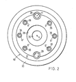
- FIG. 2 shows the ring 30, the insert spindle 10 with a through bore 35 as well as the bolt 29 and the screw 26.
- Through bores 36 in the insert spindle 10 allow the ring insert 5, not shown in more detail, to be fastened or loosened by means of the threaded holes 6 screws engaging in spindle 1 6.
- a clamping device for holding a gear to be lapped is placed on the insert spindle 10.
- An annular recess 38 is provided for centering this clamping device.
- the insert spindle 10 mounted in the direction of rotation via the elastic element (here ring body 19) can adapt much better to the vibrations caused by the meshing of the two gear wheels due to its substantially lower moment of inertia.
- the bolt 14 with the ring body 19 can be pushed more or less far into the sleeve 17, so that the ring body 19 is more or less compressed by the conical inner surface 18. So the elasticity of the elastic element can be adjusted depending on the mass of the gear to be lapped.
- the spindle insert is preferably inserted into the brake spindle of the lapping machine.
Landscapes
- Engineering & Computer Science (AREA)
- Mechanical Engineering (AREA)
- Turning (AREA)
- Finish Polishing, Edge Sharpening, And Grinding By Specific Grinding Devices (AREA)
Abstract
Description
Die Erfindung bezieht sich auf einen Spindeleinsatz für eine Spindel einer Zahnradläppmaschine.The invention relates to a spindle insert for a spindle of a gear lapping machine.
Zur Verbesserung des Tragbildes der Zähne eines Zahnradpaares können die Zahnflanken geschliffen oder geläppt werden. Beim Läppen werden die beiden Räder eines Zahnradpaares unter Zugabe von Läppmittel im Eingriff miteinander bewegt, wobei vom einen Rad zum andern ein Drehmoment übertragen wird. Zusatzbewegungen eines Rades gegenüber dem anderen, erlauben dabei, die Läppzone zu verschieben und so das Tragbild zu beeinflussen. Aus der deutschen Auslegeschrift 2 328 800 ist eine Maschine zum Läppen von Zahnrädern bekannt, die eine Spindel in üblicher Ausführungsform aufweist. Diese ist an ihrem einen Ende mit einem Innenkonus versehen, in den eine Werkstückspannvorrichtung eingesetzt werden kann. Das andere Ende der Spindel ist mit einer Antriebsvorrichtung, beispielsweise einer Riemenscheibe oder einem Kettenrad, zum Antreiben eines Bremsmotors, versehen.To improve the contact pattern of the teeth of a pair of gears, the tooth flanks can be ground or lapped. During lapping, the two wheels of a pair of gearwheels are moved in engagement with one another with the addition of lapping agents, a torque being transmitted from one wheel to the other. Additional movements of one wheel relative to the other allow the lapping zone to be shifted and thus influence the contact pattern. From the German patent specification 2 328 800 a machine for lapping gearwheels is known, which has a spindle in the usual embodiment. At one end, this is provided with an inner cone into which a workpiece clamping device can be inserted. The other end of the spindle is provided with a drive device, for example a belt pulley or a chain wheel, for driving a brake motor.
Werden an die Laufruhe eines Zahnradpaares besonders hohe Anforderungen gestellt, so können diese durch Läppen auf bekannten Maschinen, insbesondere bei hoher Läppleistung, nicht mehr erfüllt werden.If particularly high demands are placed on the smooth running of a pair of gearwheels, these can no longer be met by lapping on known machines, particularly with high lapping power.
Die Erfindung, wie sie in den Ansprüchen gekennzeichnet ist, löst die Aufgabe, eine Vorrichtung zu schaffen, mit der beim Läppen von Zahnradpaaren auf einer Zahnradläppmaschine hohe Anforderungen an das Laufverhaltendes Zahnradpaares erfüllt werden können. Die durch die Erfindung erreichten Vorteile sind insbesondere darin zu sehen, dass ein stark verbessertes Laufverhalten der Zahnräder im Einsatz, auch nach dem Läppen mit hoher Läppleistung und somit stark reduzierten Läppzeiten, möglich ist.The invention, as characterized in the claims, solves the problem of creating a device with which high demands on the running behavior of the gear pair can be met when lapping gear pairs on a gear lapping machine. The advantages achieved by the invention can be seen, in particular, in the fact that a greatly improved running behavior of the gearwheels in use is possible, even after lapping with high lapping performance and thus greatly reduced lapping times is.
Im Folgenden wird die Erfindung anhand von Zeichnungen, welche einen Ausführungsweg darstellen, näher erläutert.
Figur 1 zeigt einen Längsschnitt durch eine Spindel einer Zahnradläppmaschine mit einem Spindeleinsatz.- Figur 2 zeigt eine Ansicht eines Spindeleinsatzes.
- Figure 1 shows a longitudinal section through a spindle of a gear lapping machine with a spindle insert.
- Figure 2 shows a view of a spindle insert.
In Fig. l ist eine Spindel 1 einer Zahnradläppmaschine erkennbar, die an ihrem vorderen Ende 2 einen Innenkonus 3 aufweist. Die Spindel 1 ist in bekannter, hier nicht näher dargestellter Art in der Läppmaschine um eine Spindelachse 4 drehbar gelagert. In den Innenkonus 3 ist ein Ringeinsatz 5 eingeschoben, und mit Schrauben 6 (Fig. 2) in gestrichelt angedeuteten Gewindelöchern 6 festgeschraubt. In den Ringeinsatz 5 ist um die Spindelachse 4 drehbar und mittels Gleitlager 7 und Wälzlager 8 und 9 gelagert, eine Einsatzspindel 10 eingesetzt. Diese weist ein wesentlich geringeres Massenträgheitsmoment auf, als die Spindel 1, in der sie gelagert ist. Das Wälzlager 8 ist dabei durch Schraubringe 34, die auf der Einsatzspindel 10 aufgeschraubt und gesichert sind, befestigt.A
Parallel zur Spindelachse 4 sind zu einer Achse 11 je koaxiale Bohrungen 12 und 13 in der Einsatzspindel 10, sowie im Ringeinsatz 5 vorgesehen. Ein Bolzen 14 erstreckt sich in beide Bohrungen 12 und 13 hinein.Parallel to the
Ein Abschnitt 15 des Bolzens 14 weist den gleichen Aussendurchmesser auf, wie die Bohrung 12. Ein Abschnitt 16 weist einen wesentlich kleineren Durchmesser auf, als die Bohrung 13.A
In die Bohrung 13 ist eine Hülse 17 eingesetzt, deren Innenfläche 18 leicht konisch ausgebildet ist. Zwischen demA
Abschnitt 16 des Bolzens 14 und der Innenfläche 18 der Hülse 17 ist als elastisches Element ein elastischer Ringkörper 19 angeordnet, der auf dem Abschnitt 16 des Bolzens 14 mit einem Sprengring 20 und einer Scheibe 21 befestigt ist. Eine Abdeckscheibe 22 schützt diese Elemente gegen Verschmutzung.
Der Abschnitt 15 des Bolzens 14 weist eine Gewindebohrung 23 auf, die konzentrisch zur Achse 11 verläuft. Die Bohrung 12 wird auf dem der Bohrung 13 abgekehrten Ende durch einen Steg 24 begrenzt, der wiederum koaxial zur Achse 11 eine Durchgangsbohrung 25 für eine Schraube 26 aufweist. Mit der Schraube 26 fest verbunden ist in der Bohrung 12 eine Mutter 27 vorgesehen.The
Der Ringeinsatz 5 weist eine weitere gleich ausgeführte Bohrung 13 in Figur 1 unten mit einer Hülse 17 auf. Zu dieser verläuft koaxial in der Einsatzspindel 5 eine weitere Bohrung 28, in der ein Bolzen 29 festgemacht ist, der bis in die Bohrung 13 hineinreicht, aber einen Durchmesser aufweist, der kleiner ist, als der Durchmesser der Innenfläche 18 der Hülse 17.The
Ein Ring 30 umfasst aussen den Ringeinsatz 5 und erstreckt sich über diesen hinaus bis an eine Stirnfläche 31 der Einsatzspindel 10. Zwischen Einsatzspindel 10 und Ring 30 sind in bekannter Weise Lippendichtungen 32 und Labyrinthdichtungen 33 vorgesehen, zum Schutz gegen Verschmutzung.A
In Figur 2 erkennt man den Ring 30,'die Einsatzspindel 10 mit einer durchgehenden Bohrung 35 sowie den Bolzen 29 und die Schraube 26. Durchgangsbohrungen 36 in der Einsatzspindel 10 gestatten das nicht näher dargestellte Festmachen bzw. Lösen des Ringeinsatzes 5 mittels in die Gewindelöcher 6 in der Spindel 1 eingreifende Schrauben 6 .2 shows the
Auf die Einsatzspindel 10 wird in bekannter Art eine Aufspannvorrichtung zum Festhalten eines zu läppenden Zahnrades aufgesetzt. Zur Zentrierung dieser Aufspannvorrichtung ist eine ringförmige Ausnehmung 38 vorgesehen.In a known manner, a clamping device for holding a gear to be lapped is placed on the
Beim Läppen eines Zahnrades kann sich nun die in Drehrichtung über das elastische Element (hier Ringkörper 19) gelagerte Einsatzspindel 10 infolge ihres wesentlich geringeren Massenträgheitsmomentes den durch das Kämmen der beiden Zahnräder hervorgerufenen Schwingungen wesentlich besser anpassen.When lapping a gear wheel, the
Durch Drehen der Schraube 26 kann der Bolzen 14 mit dem Ringkörper 19 mehr oder weniger weit in die Hülse 17 hineingeschoben werden, so dass der Ringkörper 19 durch die konische Innenfläche 18 mehr oder weniger stark zusammengedrückt wird. So kann die Elastizität des elastischen Elements je nach der Masse des zu läppenden Zahnrades eingestellt werden.By turning the
Je nach Belastung und Abmessungen des Spindeleinsatzes kann es sinnvoll sein, an mehr als einer Stelle ein elastisches Element vorzusehen.Depending on the load and dimensions of the spindle insert, it may be useful to provide an elastic element in more than one place.
Vorzugweise wird der Spindeleinsatz in die Bremsspindel der Läppmaschine eingesetzt.The spindle insert is preferably inserted into the brake spindle of the lapping machine.
Claims (7)
Applications Claiming Priority (2)
| Application Number | Priority Date | Filing Date | Title |
|---|---|---|---|
| CH193081 | 1981-03-23 | ||
| CH1930/81 | 1981-03-23 |
Publications (1)
| Publication Number | Publication Date |
|---|---|
| EP0061086A1 true EP0061086A1 (en) | 1982-09-29 |
Family
ID=4221915
Family Applications (1)
| Application Number | Title | Priority Date | Filing Date |
|---|---|---|---|
| EP82101990A Withdrawn EP0061086A1 (en) | 1981-03-23 | 1982-03-12 | Spindle insert |
Country Status (5)
| Country | Link |
|---|---|
| EP (1) | EP0061086A1 (en) |
| JP (1) | JPS57168829A (en) |
| AR (1) | AR228304A1 (en) |
| AU (1) | AU8177082A (en) |
| BR (1) | BR8201583A (en) |
Cited By (4)
| Publication number | Priority date | Publication date | Assignee | Title |
|---|---|---|---|---|
| EP0154277A1 (en) * | 1984-02-28 | 1985-09-11 | I.ME.T. S.p.A. | Driving device for a turning machine tool, especially for a saw |
| WO2001043908A1 (en) * | 1999-12-17 | 2001-06-21 | The Gleason Works | Spindle for machine tool |
| EP1649972A1 (en) * | 2004-10-21 | 2006-04-26 | Mei s.r.l. | Self adjustable tool spindle with elastic connection between its two shafts |
| US8795028B2 (en) | 2004-10-04 | 2014-08-05 | The Gleason Works | Magnetic spindle for machine tool |
Citations (7)
| Publication number | Priority date | Publication date | Assignee | Title |
|---|---|---|---|---|
| GB425539A (en) * | 1933-07-17 | 1935-03-18 | Fred Badcock | Improvements in or relating to vibration dampening devices |
| US2381488A (en) * | 1942-04-01 | 1945-08-07 | Ex Cell O Corp | Rotary spindle drive |
| US2596821A (en) * | 1949-03-18 | 1952-05-13 | Gen Motors Corp | Antichatter floating toolholder |
| DE915291C (en) * | 1951-10-28 | 1954-07-19 | Heidenreich & Harbeck Gmbh | Work spindle with double bearings for machine tools, especially turning benches |
| FR1406868A (en) * | 1963-09-07 | 1965-07-23 | Karl Hueller G M B H | Damping device for tools or their supports and for machined parts or their supports |
| CH411527A (en) * | 1962-03-08 | 1966-04-15 | Klingelnberg Soehne Ferd | Machine for lapping gears |
| FR2190559A1 (en) * | 1972-06-26 | 1974-02-01 | Gleason Works |
-
1982
- 1982-03-05 AR AR28864782A patent/AR228304A1/en active
- 1982-03-12 EP EP82101990A patent/EP0061086A1/en not_active Withdrawn
- 1982-03-22 BR BR8201583A patent/BR8201583A/en unknown
- 1982-03-22 AU AU81770/82A patent/AU8177082A/en not_active Abandoned
- 1982-03-23 JP JP4475982A patent/JPS57168829A/en active Pending
Patent Citations (7)
| Publication number | Priority date | Publication date | Assignee | Title |
|---|---|---|---|---|
| GB425539A (en) * | 1933-07-17 | 1935-03-18 | Fred Badcock | Improvements in or relating to vibration dampening devices |
| US2381488A (en) * | 1942-04-01 | 1945-08-07 | Ex Cell O Corp | Rotary spindle drive |
| US2596821A (en) * | 1949-03-18 | 1952-05-13 | Gen Motors Corp | Antichatter floating toolholder |
| DE915291C (en) * | 1951-10-28 | 1954-07-19 | Heidenreich & Harbeck Gmbh | Work spindle with double bearings for machine tools, especially turning benches |
| CH411527A (en) * | 1962-03-08 | 1966-04-15 | Klingelnberg Soehne Ferd | Machine for lapping gears |
| FR1406868A (en) * | 1963-09-07 | 1965-07-23 | Karl Hueller G M B H | Damping device for tools or their supports and for machined parts or their supports |
| FR2190559A1 (en) * | 1972-06-26 | 1974-02-01 | Gleason Works |
Cited By (5)
| Publication number | Priority date | Publication date | Assignee | Title |
|---|---|---|---|---|
| EP0154277A1 (en) * | 1984-02-28 | 1985-09-11 | I.ME.T. S.p.A. | Driving device for a turning machine tool, especially for a saw |
| WO2001043908A1 (en) * | 1999-12-17 | 2001-06-21 | The Gleason Works | Spindle for machine tool |
| US6481508B2 (en) | 1999-12-17 | 2002-11-19 | The Gleason Works | Spindle for machine tool |
| US8795028B2 (en) | 2004-10-04 | 2014-08-05 | The Gleason Works | Magnetic spindle for machine tool |
| EP1649972A1 (en) * | 2004-10-21 | 2006-04-26 | Mei s.r.l. | Self adjustable tool spindle with elastic connection between its two shafts |
Also Published As
| Publication number | Publication date |
|---|---|
| AR228304A1 (en) | 1983-02-15 |
| BR8201583A (en) | 1983-02-08 |
| JPS57168829A (en) | 1982-10-18 |
| AU8177082A (en) | 1982-11-04 |
Similar Documents
| Publication | Publication Date | Title |
|---|---|---|
| DE10053183B4 (en) | Device for the automatic control of the distance between gears | |
| EP0641621B1 (en) | Rotary drive device | |
| DE60105247T2 (en) | Turntable device | |
| DE2919744A1 (en) | TORQUE-DEPENDENT SPEED SWITCHING DEVICE FOR MOTOR SCREWDRIVERS | |
| DE3732817A1 (en) | MOTOR VEHICLE COLUMN MECHANISM | |
| DE3841181A1 (en) | HAND MACHINE TOOL WITH A MULTI-PIECE MANUAL QUICK-RELEASE DEVICE | |
| DE2220790B2 (en) | Adjustable depth stop for a portable power tool | |
| DE2007849C3 (en) | Device for non-positive fastening of a gear on a shaft without a key | |
| DE3613987C2 (en) | ||
| DE69800754T2 (en) | DOUBLE-SIDED GRINDING MACHINE | |
| DE2751720C2 (en) | Mounting device for rolling bearings | |
| DE2726080C2 (en) | Arrangement for moving a rolling bearing in both axial directions | |
| DE3345800C2 (en) | Device for manufacturing and processing gears | |
| DE1139720B (en) | Device for the fine machining of gears with a shaving wheel or with another gear-shaped tool | |
| DE10322181B4 (en) | Dressing tool for dressing a grinding worm | |
| DE1440268B2 (en) | Method and machine for machining turning surfaces using electrical discharge machining | |
| DE2626912A1 (en) | MACHINE FOR MACHINING WORKPIECES | |
| DE19740208C2 (en) | Drive device for several units of a lathe | |
| DE3344548A1 (en) | METHOD AND DEVICE FOR THE PRODUCTION AND MACHINING OF GEARS | |
| EP0083672B1 (en) | Grinding wheel and method for dressing the same | |
| DE2063074C3 (en) | Underfloor wheelset lathe for the machining of wheelsets of rail vehicles | |
| DE7323671U (en) | Drive of a gear lapping machine | |
| DE2150558C3 (en) | Drill head | |
| DE2030620B2 (en) | Device for securing a grinding wheel against exceeding its maximum permissible peripheral speed | |
| DE69032677T2 (en) | HONEY TOOL AND THIS HONEY TOOL HAVING HIGH-PRECISION FINISHING PROCESS |
Legal Events
| Date | Code | Title | Description |
|---|---|---|---|
| PUAI | Public reference made under article 153(3) epc to a published international application that has entered the european phase |
Free format text: ORIGINAL CODE: 0009012 |
|
| AK | Designated contracting states |
Designated state(s): CH DE FR GB IT SE |
|
| 17P | Request for examination filed |
Effective date: 19821220 |
|
| STAA | Information on the status of an ep patent application or granted ep patent |
Free format text: STATUS: THE APPLICATION HAS BEEN WITHDRAWN |
|
| 18W | Application withdrawn |
Withdrawal date: 19831014 |
|
| RIN1 | Information on inventor provided before grant (corrected) |
Inventor name: KOTTHAUS, ERICH Inventor name: KONERSMANN, ERHARD |