EP0061099B1 - Outil d'alésage - Google Patents
Outil d'alésage Download PDFInfo
- Publication number
- EP0061099B1 EP0061099B1 EP82102020A EP82102020A EP0061099B1 EP 0061099 B1 EP0061099 B1 EP 0061099B1 EP 82102020 A EP82102020 A EP 82102020A EP 82102020 A EP82102020 A EP 82102020A EP 0061099 B1 EP0061099 B1 EP 0061099B1
- Authority
- EP
- European Patent Office
- Prior art keywords
- tool
- spindle
- boring
- drilling
- face
- Prior art date
- Legal status (The legal status is an assumption and is not a legal conclusion. Google has not performed a legal analysis and makes no representation as to the accuracy of the status listed.)
- Expired
Links
- 238000005553 drilling Methods 0.000 description 20
- 238000005452 bending Methods 0.000 description 3
- 238000013016 damping Methods 0.000 description 1
Images
Classifications
-
- B—PERFORMING OPERATIONS; TRANSPORTING
- B23—MACHINE TOOLS; METAL-WORKING NOT OTHERWISE PROVIDED FOR
- B23B—TURNING; BORING
- B23B31/00—Chucks; Expansion mandrels; Adaptations thereof for remote control
- B23B31/02—Chucks
- B23B31/10—Chucks characterised by the retaining or gripping devices or their immediate operating means
- B23B31/117—Retention by friction only, e.g. using springs, resilient sleeves, tapers
-
- B—PERFORMING OPERATIONS; TRANSPORTING
- B23—MACHINE TOOLS; METAL-WORKING NOT OTHERWISE PROVIDED FOR
- B23B—TURNING; BORING
- B23B2260/00—Details of constructional elements
- B23B2260/114—Rings
-
- B—PERFORMING OPERATIONS; TRANSPORTING
- B23—MACHINE TOOLS; METAL-WORKING NOT OTHERWISE PROVIDED FOR
- B23B—TURNING; BORING
- B23B2260/00—Details of constructional elements
- B23B2260/136—Springs
Definitions
- the invention relates to a drilling tool, in particular a boring tool equipped with a plurality of short clamp holders and / or drilling cartridges, with a conical fitting element mounted on the end face and with devices for a normal central tightening on a machine tool spindle.
- Drilling tools are often fastened in the tool holder or in the spindle of a machine tool by means of a conical fitting element, in the form of a steep taper or short taper. Larger drilling tool units, in particular special tools with a plurality of cutting units distributed over the outer surface of the drill shank, are also anchored in the spindle of the machine tool via a normal central suit.
- the diameter of the fitting cone (D) limits the length of the drilling tool, the maximum permissible shaft length for drilling tools with individual cutting elements distributed over the shaft surface being from a value D x 5 to max. D x 6 is to go out. This reference comes from practice.
- the drilling tool Since the drilling tool is connected to the machine spindle via the fitting cone and generally has the smallest diameter in this area, this determines the bending moment on the drilling tool caused by forces acting perpendicular to the longitudinal axis. Furthermore, the diameter D decisively determines the vibrations that occur on the drilling tool during operation. It is now theoretically conceivable to improve the connection of the spindle and tool by extending the precisely fitting system between the two parts beyond the area of the fitting cone to the adjacent plane surface. In practice, however, such a solution fails due to the fact that support surfaces of a corresponding fit for the fitting cone and also for the subsequent radial plane surface cannot be produced or cannot be produced economically.
- Drilling tools are usually designed so that the radial surfaces of the spindle and tool have a gap width of 0.3-0.4 mm when clamped, provided that the tool diameter is greater than that of the fitting taper diameter.
- the maximum permissible tool length is often considered unsatisfactory.
- a boring bar is known, the boring head of which is connected to the boring bar shaft by means of a disk spring and a conically bevelled disc with the aid of a central suit. Since the drill head has no conical fitting element and the disc between the disc spring and the drill rod shaft is beveled conically, a rigid, non-positive connection between the drill head and the drill rod shaft is deliberately largely avoided.
- the arrangement is used exclusively to avoid vibrations, the vibration stability can be changed by changing the bias of the plate spring.
- the arrangement is used exclusively to avoid vibrations of the drill head.
- the use of the described arrangement for connecting the boring bar shaft to a machine tool spindle is at most limited to small dimensions. Boring bars in lengths commonly used today, in which correspondingly large bending moments occur, cannot be held satisfactorily in the machine tool spindle by means of the arrangement described above.
- the object of the present invention is to provide a connection between the drilling tool and the machine spindle of the type mentioned in the introduction, in which the maximum length of the drilling tool determined by the predetermined fitting cone diameter of the machine spindle can be increased and the risk of vibration of the tool is simultaneously reduced during work.
- the object is achieved in that the drilling tool has one or more devices for receiving disc springs in a radial area outside the fitting element, which devices can be displaced axially against spring force and, when the tool is clamped, bear flat against the spindle face under spring pressure.
- the plate springs are inserted into a cylinder liner closed at one end.
- a ring protruding laterally beyond the cylinder liner is pushed onto the disc springs.
- the cylinder liners are located in holes in the end face of the tool, with the closed side of the cylinder liners protruding laterally beyond the end face of the tool.
- the plate springs are in several holes drilled in the face of the tool.
- the bores are closed by piston-like cylinders that protrude slightly beyond the tool face.
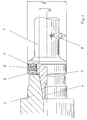
- the invention is illustrated by the single figure. The tool and spindle are shown partly in section and partly in top view.
- the shaft 1 of the drilling tool is connected to the spindle 3 via a steep taper 2 and is held in the spindle via elements for a central tightening 4.
- the outer face of the spindle-side end face of the drilling tool contains an annular device 5, into which six blind holes for receiving disc springs 6 are made.
- the plate springs are held in the blind holes of the device via rings 7.
- the ring projects beyond the end of the ring-shaped device facing the boring bar; on the other hand, the other end of the device projects beyond the end face of the tool and rests flat under spring pressure on the radial end face of the spindle.
- the tool and spindle are worked so precisely that the ring-shaped device mainly moves in the direction of the longitudinal axis of the tool and can only be tilted slightly against the tool axis.
- a short-clamping tool 8 which is introduced into the surface of the tool, is indicated.
Landscapes
- Engineering & Computer Science (AREA)
- Mechanical Engineering (AREA)
- Auxiliary Devices For Machine Tools (AREA)
Claims (1)
- Dans un outil d'alésage, en particulier un outil de réalésage, qui est équipé d'un grand nombre de cartouches (8) et/ou de gabarits d'alésage, outre la fixation de l'outil d'alésage avec la broche (3) de la machine-outil par l'intermédiaire d'un élément adaptateur disposé frontalement, par exemple sous la forme d'un cône rapide et d'un entraînement central normal (4), sont prévues des mesures de fixation supplémentaires. L'outil d'alésage comporte à cet effet frontalement, dans une région radiale à l'extérieur de l'élément adaptateur (2), un ou plusieurs dispositifs (5) pour recevoir des ressorts Belleville (6), les dispositifs (5) pouvant se déplacer suivant la direction axiale à l'encontre de la force des ressorts et, lorsque l'outil est serré, s'appuyant de façon plane sur la surface frontale de l'outil sous l'action des ressorts. De cette manière, la longueur maximale de l'outil, qui dépend du diamètre, peut être augmentée. Simultanément la stabilité vis- à-vis des oscillations est améliorée.
Applications Claiming Priority (2)
| Application Number | Priority Date | Filing Date | Title |
|---|---|---|---|
| AT1192/81 | 1981-03-16 | ||
| AT119281A AT376386B (de) | 1981-03-16 | 1981-03-16 | Bohrwerkzeug |
Publications (2)
| Publication Number | Publication Date |
|---|---|
| EP0061099A1 EP0061099A1 (fr) | 1982-09-29 |
| EP0061099B1 true EP0061099B1 (fr) | 1984-01-25 |
Family
ID=3508597
Family Applications (1)
| Application Number | Title | Priority Date | Filing Date |
|---|---|---|---|
| EP82102020A Expired EP0061099B1 (fr) | 1981-03-16 | 1982-03-12 | Outil d'alésage |
Country Status (3)
| Country | Link |
|---|---|
| EP (1) | EP0061099B1 (fr) |
| AT (1) | AT376386B (fr) |
| DE (1) | DE3260036D1 (fr) |
Family Cites Families (1)
| Publication number | Priority date | Publication date | Assignee | Title |
|---|---|---|---|---|
| DE7829916U1 (de) * | 1978-10-06 | 1979-02-15 | Jud Ag Klemmwerkzeuge, Ruggell (Liechtenstein) | Bohrwerkzeug |
-
1981
- 1981-03-16 AT AT119281A patent/AT376386B/de not_active IP Right Cessation
-
1982
- 1982-03-12 DE DE8282102020T patent/DE3260036D1/de not_active Expired
- 1982-03-12 EP EP82102020A patent/EP0061099B1/fr not_active Expired
Non-Patent Citations (1)
| Title |
|---|
| "Soviet Inventions Illustrated" Week C 06, 10. März 1980 Section P 54 * |
Also Published As
| Publication number | Publication date |
|---|---|
| EP0061099A1 (fr) | 1982-09-29 |
| DE3260036D1 (en) | 1984-03-01 |
| AT376386B (de) | 1984-11-12 |
| ATA119281A (de) | 1984-04-15 |
Similar Documents
| Publication | Publication Date | Title |
|---|---|---|
| DE3504905C2 (fr) | ||
| DE2339873C2 (de) | Anordnung zum Einstellen und Befestigen eines ein Schneidplättchen tragenden Blocks in einer nutförmigen Aufnahme im Werkzeugkörper eines spanabhebenden Werkzeugs | |
| EP0259517B1 (fr) | Broche pour le coulant d'une machine-outil, munie d'un seul évidement pour le montage d'un outil de tournage ou de fraisage | |
| EP0773849A2 (fr) | Outil de finition pour l'usinage de precision de trous | |
| DE3838959A1 (de) | Werkzeugspannvorrichtung | |
| DE69813820T2 (de) | Bohrkopf mit vibrationseffekt | |
| DE8415796U1 (de) | Vorrichtung zum Verbinden eines Werkzeugteils mit einem Anschlußschaft | |
| DE2523201C2 (de) | Spitzbohrwerkzeug | |
| DE9212205U1 (de) | Spannvorrichtung zum Verbinden von Maschinenspindeln mit Werkzeughaltern | |
| DE3819499A1 (de) | Ausdrehvorrichtung | |
| DE3434202A1 (de) | Revolverkopf fuer eine drehmaschine und hierzu passende werkzeughalter | |
| DE69227931T2 (de) | Anordnung für Werkzeuge in eingeschränkten Räumen | |
| EP0972613B1 (fr) | Toc d'entraínement pour machine outil | |
| EP0214927B1 (fr) | Mandrin pour outils de forage et de burinage | |
| EP0264599B1 (fr) | Outil d'alésage | |
| EP0061099B1 (fr) | Outil d'alésage | |
| EP1259350B1 (fr) | Outil de frottement avec tige de guidage | |
| DE2436501B2 (de) | Bohrstange | |
| DE3926025C1 (en) | Machine tool precision boring head - has sprung tool support incorporating cooling line | |
| DE3150966A1 (de) | Spannbacke | |
| EP0275911A1 (fr) | Dispositif d'accouplement de deux pièces à rotation symétrique par exemple une tête d'outil et un porte-outil dans des machines-outils | |
| DE3419154C2 (fr) | ||
| DE2360000C3 (de) | Werkzeugeinsatz für Bohrstangen u. dgl. Werkzeughalter mit zwei gegenläufig bewegbaren Bohrstahlträgern | |
| DE69223873T2 (de) | Bohrkopf | |
| DE2759840C2 (de) | Werkzeughalter für Einstecharbeiten, insbesondere in Bohrungen |
Legal Events
| Date | Code | Title | Description |
|---|---|---|---|
| PUAI | Public reference made under article 153(3) epc to a published international application that has entered the european phase |
Free format text: ORIGINAL CODE: 0009012 |
|
| AK | Designated contracting states |
Designated state(s): DE FR GB IT |
|
| 17P | Request for examination filed |
Effective date: 19820823 |
|
| ITF | It: translation for a ep patent filed | ||
| GRAA | (expected) grant |
Free format text: ORIGINAL CODE: 0009210 |
|
| AK | Designated contracting states |
Designated state(s): DE FR GB IT |
|
| REF | Corresponds to: |
Ref document number: 3260036 Country of ref document: DE Date of ref document: 19840301 |
|
| ET | Fr: translation filed | ||
| PLBE | No opposition filed within time limit |
Free format text: ORIGINAL CODE: 0009261 |
|
| STAA | Information on the status of an ep patent application or granted ep patent |
Free format text: STATUS: NO OPPOSITION FILED WITHIN TIME LIMIT |
|
| 26N | No opposition filed | ||
| PGFP | Annual fee paid to national office [announced via postgrant information from national office to epo] |
Ref country code: FR Payment date: 19900215 Year of fee payment: 9 |
|
| PGFP | Annual fee paid to national office [announced via postgrant information from national office to epo] |
Ref country code: DE Payment date: 19900217 Year of fee payment: 9 |
|
| PGFP | Annual fee paid to national office [announced via postgrant information from national office to epo] |
Ref country code: GB Payment date: 19900228 Year of fee payment: 9 |
|
| ITTA | It: last paid annual fee | ||
| PG25 | Lapsed in a contracting state [announced via postgrant information from national office to epo] |
Ref country code: GB Effective date: 19910312 |
|
| GBPC | Gb: european patent ceased through non-payment of renewal fee | ||
| PG25 | Lapsed in a contracting state [announced via postgrant information from national office to epo] |
Ref country code: FR Effective date: 19911129 |
|
| PG25 | Lapsed in a contracting state [announced via postgrant information from national office to epo] |
Ref country code: DE Effective date: 19920101 |
|
| REG | Reference to a national code |
Ref country code: FR Ref legal event code: ST |