EP0061129B2 - Dispositif à volet pour installation de commutation blindée - Google Patents
Dispositif à volet pour installation de commutation blindée Download PDFInfo
- Publication number
- EP0061129B2 EP0061129B2 EP19820102130 EP82102130A EP0061129B2 EP 0061129 B2 EP0061129 B2 EP 0061129B2 EP 19820102130 EP19820102130 EP 19820102130 EP 82102130 A EP82102130 A EP 82102130A EP 0061129 B2 EP0061129 B2 EP 0061129B2
- Authority
- EP
- European Patent Office
- Prior art keywords
- actuating lever
- fulcrum
- shutter device
- switch box
- rod
- Prior art date
- Legal status (The legal status is an assumption and is not a legal conclusion. Google has not performed a legal analysis and makes no representation as to the accuracy of the status listed.)
- Expired
Links
- 239000004020 conductor Substances 0.000 description 4
- 238000003780 insertion Methods 0.000 description 3
- 230000037431 insertion Effects 0.000 description 3
- 238000005192 partition Methods 0.000 description 3
- 238000007689 inspection Methods 0.000 description 2
- 238000010276 construction Methods 0.000 description 1
- 230000000994 depressogenic effect Effects 0.000 description 1
- 238000011161 development Methods 0.000 description 1
- 230000018109 developmental process Effects 0.000 description 1
- 238000009413 insulation Methods 0.000 description 1
- 238000012423 maintenance Methods 0.000 description 1
- 238000005259 measurement Methods 0.000 description 1
- 239000002184 metal Substances 0.000 description 1
- 230000001681 protective effect Effects 0.000 description 1
Images

Classifications
-
- H—ELECTRICITY
- H02—GENERATION; CONVERSION OR DISTRIBUTION OF ELECTRIC POWER
- H02B—BOARDS, SUBSTATIONS OR SWITCHING ARRANGEMENTS FOR THE SUPPLY OR DISTRIBUTION OF ELECTRIC POWER
- H02B11/00—Switchgear having carriage withdrawable for isolation
- H02B11/24—Shutters or guards
Definitions
- the present invention relates to a shutter device for metal-enclosed switchgear and concerns an improvement in positioning of a fulcrum for an actuating lever for opening and closing the shutter device.
- a metal-enclosed switchgear comprises a circuit breaker of the drawout type adapted to be detachably inserted into a switch box so as to contact the disconnecting contacts provided in the switch box, where one group of which is connected to the source side and another to the load side.
- a shutter device is provided in the switchgear to cover the disconnecting contacts when the circuit breaker is withdrawn from the switch box and to uncover the same during the insertion of the circuit breaker into the switch box.
- a shutter device is known from US-A-3 015 756, which comprises shutters to cover and uncover the disconnecting contacts and a rod supporting the shutters.
- the rod is secured to one end of an actuating lever supported by a fulcrum or pivot secured to the base of the switch box.
- the actuating lever is adapted to make an engagement with an operating roller provided on the circuit breaker.
- the arrangement is such that, as the circuit breaker is inserted into and withdrawn from the switch box, the actuating lever is rotated up and down around the fulcrum so that the shutters are also moved up and down to cover and uncover the disconnecting contacts.
- the fulcrum is located at the outer end of the actuating lever, i. e.
- the operater For making an inspection of the disconnecting contacts on the source or load side, such as measurement of the insulation resistance after the withdrawal of the circuit breaker, the operater has to uncover the disconnecting contacts. This action requires a considerable force because the fulcrum is located at the outer end of the actuating lever facing to the side of the entrance of the switch box.
- a shutter device is known in accordance with the prior art portion of claim 1 (prospectus entitled "Normalschaltanlagen mit ausfahrbaren Geraten” of Felten & Guilleaume Carlswerk AG).
- This shutter device has a similar construction as the shutter device mentioned above.
- the fulcrum attached to the wall of the switch box via a frame is disposed at a position balanced between the opposite ends of the actuating lever, wherein the operating device being adapted to slide between the fulcrum and the outer end of the actuating lever.
- a further shutter device is known from US-A-3 213 222 in which the fulcrum is disposed between the ends of the actuating lever and the operating device is adapted to slide between the fulcrum and the inner end of the actuating lever.
- a shutter device in which the actuating lever is provided between said fulcrum and the outer end with a portion raising above a portion between said fulcrum and the inner end of the actuating lever.
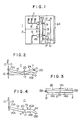
- Fig. 1 shows a metal-enclosed switchgear 1 to which the present invention is applied.
- the metal-enclosed switchgear 1 has a switch box 2 which is provided at its one side with an entrance adapted to be opened and closed by means of a door 2A.
- a partition wall 3 is mounted in the switch box 2.
- An upper disconnecting contact 4A secured to the partition wall 3 is connected to source-side conductors 5 having three phases, while a lower disconnecting contact 4B also secured to the partition wall 3 is connected to loadside conductors 6 having three phases.
- the source-side conductors 5 are connected to source bus 7 while the loadside conductors 6 are connected to a load which is not shown.
- disconnecting contacts 4A, 4B are adapted to be contacted at their outer sides by disconnecting contacts 9 of a circuit breaker 8.
- the circuit breaker 8 is provided with wheels 10 by means of which it is easily moved into the switch box to connect the contacts 9 with the disconnecting contacts 4A and 4B.
- the contacts 9 are electrically separated from the stationary disconnecting contacts 4A and 4B to expose the disconnecting contacts 4A and 4B one or both of which are charged electrically to high voltage.
- a shutter device 11 is provided to cover and uncover the disconnecting contacts in accordance with withdrawal and insertion of the circuit breaker into the switch box.
- the detail of the shutter device 11 will be explained hereinunder with reference to Fig. 2.
- the shutter device 11 has shutters 12 adapted for covering the disconnecting contacts 4A, 4B and secured to a rod 13 in a constant distance.
- the rod 13 is fixed by means of a fixing means 16 to the inner end 15A of an actuating lever 14 adjacent to the rod 13.
- the actuating lever 14 extends along the side wall of the switch box.
- the side wall is marked with reference number 22 in Fig. 6.
- the actuating lever 14 is rotatably supported by a fulcrum 17 fixed to the side wall of the switch box.
- the position of the fulcrum 17 will be explained with reference to Fig. 3.
- the length of the first portion 14A of the operating lever 14, bounded by the inner end 15A and the fulcrum 17, is represented by 1 1
- the length of the second portion 14B of the lever bounded by the fulcrum 17 and the outer end 15B is represented by 1 2 .
- the position of the fulcrum is selected to meet the following condition:
- the fulcrum is located at a point which permits the first portion 14A of the actuating lever 14 to descend under the combined weights of the shutters 12 and the rod.
- This position of fulcrum is usually located at a point 14C near the mid point of the actuating lever.
- the circuit breaker 8 is provided with an operating roller 20 adapted to engage the upper surface of the actuating lever 14 to rotate the actuating lever 14 up and down around the fulcrum 17 in accordance with the insertion and withdrawal of the circuit breaker 8 into and out of the switch box.
- the operating roller 20 slides on the upper surface of the second portion 14B.
- the aforementioned product A takes a value greater than the product B when the circuit breaker 8 has been withdrawn from the breaker compartment.
- the moment of rotation acting on the first portion 14A of the actuating lever 14 is greater than that on the second portion 14B by an amount corresponding to the total weight of the shutters 12 and the rod 13. Therefore, a balance of moment is obtained when the actuating lever takes the position illustrated by chain line in which the first portion 14A is lowered while the second portion 14B is raised around the fulcrum 17. In this state, the disconnecting contacts are covered by the shutters 12.
- the product B assumes a value greater than the product A.
- the second portion 14B is rotated downward while the first portion 14A is rotated upward around the fulcrum 17, so that the actuating lever takes a position shown by solid line in Fig. 2.
- the shutters 12 are moved upward to uncover the disconnecting contacts.
- the balance of moment is maintained in such a state that the first portion of the operating lever is lowered as compared with the second portion by a height corresponding to the weight of the shutters and the rod. Therefore, as a force is applied to the second portion, the shutters are moved easily to uncover the disconnecting contacts.
- Fig. 4 shows another embodiment in which an auxiliary roller 20A is mounted at a portion of the circuit breaker 8 corresponding to the second portion of the actuating lever 14 besides the aforementioned operating roller 20 mounted on the portion of the circuit breaker 8 corresponding to the first portion 14A.
- the roller 20 acts to depress the first portion 14A of the actuating lever 14 downwardly as indicated by an arrow Y 1 to cause a tendency to move the second portion 14B of the same upwardly as indicated by an arrow Y 2 .
- This tendency is perfectly suppressed by the auxiliary roller 20A which acts to depress the second portion 14B.
- the second portion 14B of the actuating lever 14 is provided with an upward projection 24 which rises above the level of the first portion 14A when the actuating lever 14 takes the position shown by chain line in Fig. 2.
- the shutters 12 are raised without delay so that it is possible to increase the speed of uncovering action of the shutters.
- Fig. 5 shows still another embodiment in which the shutter device 11 is constructed to include an upward projection 24A, and a tension spring 13A which pulls the rod 13 and the shutters 12 upwardly when the circuit breaker 8 is not contained in the metal-enclosed switchgear 1.
- the tension spring 13A is stretched between supporting tabs 13B and 13C provided on the rod 13.
- the shutter device 11 of this embodiment operates in a manner explained hereinunder. Namely, as the circuit breaker 8 is moved toward the disconnecting contacts 4A, 4B, the operating roller 20 slides in contact with the lower side of the projection 24A, so that the actuating lever 14 is raised to the position shown by chain line from the position shown by solid line around the fulcrum. In consequence, the rod 13 is lowered against the tension spring 13A. In this state, the shutters 12 uncover the disconnecting contacts 4A, 4B for exposure. Conversely, as the circuit breaker 8 is withdrawn from the metal-enclosed switchgear 1, the tension spring 13A contracts to raise the rod and shutters and to take the position shown by the solid line so that the shutters 13 cover the disconnecting contacts 4A, 4B. As the operator lifts the outer end 15B, it is possible to further lower the shutters 12 to achieve the same result as the foregoing embodiments.
- Figs. 6A, 6B and 6C show a further embodiment of the invention having a latching mechanism adapted to prevent an unintentional operation of the shutter due to any accidental touch on the actuating lever by the operator when the circuit breaker 8 has been withdrawn from the switch box 2.
- a case 23 is provided on the side wall 22 of the switch box opposing to the actuating lever 14.
- the case 23 accommodates a pressure plate 25 loaded by a spring 28 and a stopper 26 provided on the pressure plate 25.
- the stopper 26 continuously urges the actuating lever 14.
- the actuating lever 14 is provided with a through hole 27 for receiving the stopper 26.
- one end 25A of the pressure plate 25 movable in an elongated hole (not shown) in the case 23 is moved away from the actuating lever 14 to move the stopper 26 out of the through hole 27.
- the stopper 26 which prevents the rotation of the actuating lever 14
- the fulcrum of the actuating lever is disposed at a location balanced between the opposite ends of the lever and the operating device is adapted to slide between the fulcrum and the outer end of the actuating lever.
- the outer end of the actuating lever at which the actuating lever is manipulated by the operator is located remote from the contact sections, the danger of accidental touch of the operator's body with the electrically charged disconnecting contacts is avoided to ensure safety during protective maintenance and inspection of the switchgear.
Landscapes
- Engineering & Computer Science (AREA)
- Power Engineering (AREA)
- Trip Switchboards (AREA)
Claims (6)
Applications Claiming Priority (2)
| Application Number | Priority Date | Filing Date | Title |
|---|---|---|---|
| JP37948/81 | 1981-03-18 | ||
| JP3794881A JPS57153502A (en) | 1981-03-18 | 1981-03-18 | Shutter unit for enclosed switchboard |
Publications (3)
| Publication Number | Publication Date |
|---|---|
| EP0061129A1 EP0061129A1 (fr) | 1982-09-29 |
| EP0061129B1 EP0061129B1 (fr) | 1985-08-28 |
| EP0061129B2 true EP0061129B2 (fr) | 1990-02-28 |
Family
ID=12511766
Family Applications (1)
| Application Number | Title | Priority Date | Filing Date |
|---|---|---|---|
| EP19820102130 Expired EP0061129B2 (fr) | 1981-03-18 | 1982-03-16 | Dispositif à volet pour installation de commutation blindée |
Country Status (3)
| Country | Link |
|---|---|
| EP (1) | EP0061129B2 (fr) |
| JP (1) | JPS57153502A (fr) |
| DE (1) | DE3265719D1 (fr) |
Families Citing this family (4)
| Publication number | Priority date | Publication date | Assignee | Title |
|---|---|---|---|---|
| DE3320739A1 (de) * | 1983-06-09 | 1984-12-13 | Licentia Patent-Verwaltungs-Gmbh, 6000 Frankfurt | Anordnung zum verschieben eines schiebers |
| DE3544667A1 (de) * | 1985-12-13 | 1987-06-19 | Siemens Ag | Einschubrahmen mit einer schutzplatte fuer eine trennkontaktanordnung |
| US8085528B2 (en) * | 2008-05-13 | 2011-12-27 | General Electric Company | Apparatus and method for an electrical system enclosure |
| DE102013019064B4 (de) | 2013-11-15 | 2022-03-31 | Abb Ag | Schaltanlage mit zugänglichen Stromschienen |
Family Cites Families (2)
| Publication number | Priority date | Publication date | Assignee | Title |
|---|---|---|---|---|
| US3015756A (en) * | 1958-11-26 | 1962-01-02 | Allis Chalmers Mfg Co | Enclosed switchboard employing switch carrier for dismantling transformers |
| US3213222A (en) * | 1963-04-12 | 1965-10-19 | Westinghouse Electric Corp | Switchgear shutter |
-
1981
- 1981-03-18 JP JP3794881A patent/JPS57153502A/ja active Pending
-
1982
- 1982-03-16 DE DE8282102130T patent/DE3265719D1/de not_active Expired
- 1982-03-16 EP EP19820102130 patent/EP0061129B2/fr not_active Expired
Also Published As
| Publication number | Publication date |
|---|---|
| JPS57153502A (en) | 1982-09-22 |
| DE3265719D1 (en) | 1985-10-03 |
| EP0061129A1 (fr) | 1982-09-29 |
| EP0061129B1 (fr) | 1985-08-28 |
Similar Documents
| Publication | Publication Date | Title |
|---|---|---|
| US4002865A (en) | Drawout type circuit interrupter with interlocked levering mechanism | |
| US2777024A (en) | Metal-enclosed switchgear | |
| US3920939A (en) | Circuit breaker protective shutter apparatus | |
| US4110584A (en) | Load break switch with transparent internal shield | |
| US4146915A (en) | Shutter mechanism for an enclosed electrical switchboard | |
| EP0061129B2 (fr) | Dispositif à volet pour installation de commutation blindée | |
| US6624996B2 (en) | Safety device applied to engaging and disengaging a fuse in medium voltage electrical gear | |
| KR102623174B1 (ko) | 회전형 셔터 구조를 갖는 배전반 | |
| US2534938A (en) | Circuit breaker | |
| US3784774A (en) | Vacuum circuit breaker current transfer and actuation | |
| US3229057A (en) | Metal clad circuit-breakers for high voltages | |
| US3368053A (en) | Circuit interrupter with interlock means and terminal cover | |
| DK165471B (da) | Elektrisk kobleudstyr | |
| US3179762A (en) | Enclosed electrical switchgear with protective hinged access cover | |
| US3089928A (en) | Operating mechanism for enclosed circuit interrupter | |
| US3295025A (en) | Movable barrier serving as shutter means and enclosure door in switchgear housing | |
| US3842321A (en) | Electrical switchgear with primary and secondary switch means associated with current transformer | |
| US1971831A (en) | Electrical switch gear | |
| JPS6316246Y2 (fr) | ||
| GB460971A (en) | Improvements in or relating to electric circuit-breakers | |
| US3582591A (en) | Quick-opening and quick-closing circuit breaker with toggle action, and a concentric double shaft | |
| US1966218A (en) | Electrical switch gear | |
| JPH0231842Y2 (fr) | ||
| JPS6031365Y2 (ja) | 開閉装置の操作機構 | |
| JPS6019455Y2 (ja) | 閉鎖配電盤 |
Legal Events
| Date | Code | Title | Description |
|---|---|---|---|
| PUAI | Public reference made under article 153(3) epc to a published international application that has entered the european phase |
Free format text: ORIGINAL CODE: 0009012 |
|
| AK | Designated contracting states |
Designated state(s): DE FR GB |
|
| 17P | Request for examination filed |
Effective date: 19830126 |
|
| GRAA | (expected) grant |
Free format text: ORIGINAL CODE: 0009210 |
|
| AK | Designated contracting states |
Designated state(s): DE FR GB |
|
| REF | Corresponds to: |
Ref document number: 3265719 Country of ref document: DE Date of ref document: 19851003 |
|
| ET | Fr: translation filed | ||
| PLBI | Opposition filed |
Free format text: ORIGINAL CODE: 0009260 |
|
| 26 | Opposition filed |
Opponent name: FELTEN & GUILLEAUME ENERGIETECHNIK GMBH Effective date: 19860502 |
|
| PUAH | Patent maintained in amended form |
Free format text: ORIGINAL CODE: 0009272 |
|
| STAA | Information on the status of an ep patent application or granted ep patent |
Free format text: STATUS: PATENT MAINTAINED AS AMENDED |
|
| 27A | Patent maintained in amended form |
Effective date: 19900228 |
|
| AK | Designated contracting states |
Kind code of ref document: B2 Designated state(s): DE FR GB |
|
| EN | Fr: translation not filed | ||
| EN3 | Fr: translation not filed ** decision concerning opposition | ||
| ET3 | Fr: translation filed ** decision concerning opposition | ||
| REG | Reference to a national code |
Ref country code: FR Ref legal event code: BR |
|
| PGFP | Annual fee paid to national office [announced via postgrant information from national office to epo] |
Ref country code: FR Payment date: 20010222 Year of fee payment: 20 |
|
| PGFP | Annual fee paid to national office [announced via postgrant information from national office to epo] |
Ref country code: GB Payment date: 20010226 Year of fee payment: 20 |
|
| PGFP | Annual fee paid to national office [announced via postgrant information from national office to epo] |
Ref country code: DE Payment date: 20010330 Year of fee payment: 20 |
|
| REG | Reference to a national code |
Ref country code: GB Ref legal event code: IF02 |
|
| PG25 | Lapsed in a contracting state [announced via postgrant information from national office to epo] |
Ref country code: GB Free format text: LAPSE BECAUSE OF EXPIRATION OF PROTECTION Effective date: 20020315 |
|
| REG | Reference to a national code |
Ref country code: GB Ref legal event code: PE20 Effective date: 20020315 |