EP0061164B1 - Appareil doseur tubulaire pour délivrer des quantités identiques de fluide - Google Patents
Appareil doseur tubulaire pour délivrer des quantités identiques de fluide Download PDFInfo
- Publication number
- EP0061164B1 EP0061164B1 EP82102249A EP82102249A EP0061164B1 EP 0061164 B1 EP0061164 B1 EP 0061164B1 EP 82102249 A EP82102249 A EP 82102249A EP 82102249 A EP82102249 A EP 82102249A EP 0061164 B1 EP0061164 B1 EP 0061164B1
- Authority
- EP
- European Patent Office
- Prior art keywords
- passage
- opening
- volume
- liquid
- dosage device
- Prior art date
- Legal status (The legal status is an assumption and is not a legal conclusion. Google has not performed a legal analysis and makes no representation as to the accuracy of the status listed.)
- Expired
Links
- 239000012530 fluid Substances 0.000 title 1
- 239000007788 liquid Substances 0.000 claims abstract description 90
- 238000005192 partition Methods 0.000 claims abstract description 9
- 238000005273 aeration Methods 0.000 claims 1
- 238000009423 ventilation Methods 0.000 description 5
- XLYOFNOQVPJJNP-UHFFFAOYSA-N water Substances O XLYOFNOQVPJJNP-UHFFFAOYSA-N 0.000 description 4
- 239000004033 plastic Substances 0.000 description 3
- 238000010276 construction Methods 0.000 description 2
- 238000001746 injection moulding Methods 0.000 description 2
- 238000000034 method Methods 0.000 description 2
- 230000002093 peripheral effect Effects 0.000 description 2
- 230000003014 reinforcing effect Effects 0.000 description 2
- 230000007704 transition Effects 0.000 description 2
- 239000004743 Polypropylene Substances 0.000 description 1
- 238000004026 adhesive bonding Methods 0.000 description 1
- 230000000694 effects Effects 0.000 description 1
- -1 polypropylene Polymers 0.000 description 1
- 229920001155 polypropylene Polymers 0.000 description 1
- 230000000717 retained effect Effects 0.000 description 1
- 238000007142 ring opening reaction Methods 0.000 description 1
- 238000007789 sealing Methods 0.000 description 1
- 238000003466 welding Methods 0.000 description 1
Images

Classifications
-
- G—PHYSICS
- G01—MEASURING; TESTING
- G01F—MEASURING VOLUME, VOLUME FLOW, MASS FLOW OR LIQUID LEVEL; METERING BY VOLUME
- G01F11/00—Apparatus requiring external operation adapted at each repeated and identical operation to measure and separate a predetermined volume of fluid or fluent solid material from a supply or container, without regard to weight, and to deliver it
- G01F11/10—Apparatus requiring external operation adapted at each repeated and identical operation to measure and separate a predetermined volume of fluid or fluent solid material from a supply or container, without regard to weight, and to deliver it with measuring chambers moved during operation
- G01F11/26—Apparatus requiring external operation adapted at each repeated and identical operation to measure and separate a predetermined volume of fluid or fluent solid material from a supply or container, without regard to weight, and to deliver it with measuring chambers moved during operation wherein the measuring chamber is filled and emptied by tilting or inverting the supply vessel, e.g. bottle-emptying apparatus
- G01F11/262—Apparatus requiring external operation adapted at each repeated and identical operation to measure and separate a predetermined volume of fluid or fluent solid material from a supply or container, without regard to weight, and to deliver it with measuring chambers moved during operation wherein the measuring chamber is filled and emptied by tilting or inverting the supply vessel, e.g. bottle-emptying apparatus for liquid or semi-liquid
Definitions
- the invention relates to a tubular metering device for dispensing quantities of liquid of the same volume from liquid containers, which are provided with a dispensing opening into which the metering device can be inserted, so that the dispensing opening is closed by the metering device sealed against the container wall, with one in it Inner dosing channel extending in the axial direction, open to the outer end with respect to the liquid container, and a dosing channel, which extends in the interior in the axial direction and closed to the outer end, are separated from one another by a dividing wall which is at a distance from the inner end of the dosing device occluding bottom ends, so that between the bottom and the end of the partition a dosing channel and the pouring channel connecting collecting space is formed, the volume of which is at least equal to the volume to be dosed, the dosing channel corresponding to two at an axial distance hend the volume to be metered openings is connected to the interior of the container and a collecting space is formed in the metering channel between the
- the two openings connecting the metering channel to the interior of the liquid container are located in the side wall of the metering device, specifically the one opening directly on the transverse wall closing the metering channel at the outer end and the other opening at a corresponding axial distance from the first opening, so that the two openings lie on a straight line parallel to the longitudinal axis of the metering device.
- liquid flows from the interior of the container through the axially outermost opening in the wall of the metering channel into the latter until the liquid level in the metering channel has risen so high is that, when the liquid container is upside down, it closes the second opening. In this state, air can no longer get into the interior of the liquid container and the volume of liquid to be dispensed has been reached.
- the amount of free liquid is thus different in size, whereby this free liquid cannot flow out of the metering channel, so that actually only half of the theoretically possible amount of free liquid gets into the metering channel and thereby the other half is retained in the interior of the liquid container.
- the free liquid exiting into the metering channel in the known metering device beyond the desired volume has the effect that a certain negative pressure is created in the interior of the liquid container. If the liquid container is then tilted back into its normal position, the free liquid which has entered the dosing channel is sucked back into the interior of the container through the second opening in the wall of the dosing channel during this process due to the negative pressure in the liquid container, while this is due to the distance between the two Openings in the wall of the metering channel reach certain liquid volumes in the collecting space between the end of the partition and the bottom of the metering device. From here, the liquid can then be dispensed through the pouring channel by tilting the liquid container, and with a corresponding tilting, a new liquid volume of the desired size will also enter the metering channel at the same time.
- the known metering device has the disadvantage of relatively great inaccuracy in the determination of the liquid volume to be dispensed, because the liquid level in the metering channel can be different in that the user brings the liquid container to fill the metering channel in different inclination positions, the desired volume being obtained exactly when the Liquid container is turned upside down in such a way that the longitudinal axis of the metering channel is perpendicular.
- the metered liquid volume is either larger or smaller than desired because the liquid closes both openings in the wall of the metering channel, but the liquid level corresponds to the deviation of the longitudinal axis of the metering channel from the vertical with respect to the longitudinal axis is inclined. i.e. the deviation of the liquid level from a plane perpendicular to the longitudinal axis of the metering chamber resulting from the inclination causes a difference in the liquid volume from the volume to be dispensed per se.
- a metering device of the type mentioned at the outset is designed in such a way that the opening furthest from the outer end is formed by the opening of a channel extending through the bottom wall into the metering channel, the opening preferably being arranged coaxially to the longitudinal axis of the metering channel is.
- the position of the size of the volume to be dispensed in the metering channel is no longer in the side wall of the metering channel, but rather in the center thereof, preferably on its longitudinal axis, if the longitudinal axis of the metering channel deviates from the vertical during Filling the metering channel as in the known metering device a liquid level deviating from the vertical plane to the longitudinal axis of the metering channel does occur, but this liquid level will lie on one side of the mouth opening below and on the opposite side of the mouth opening above it, ie the too low and the too high fill level with respect to the mouth opening compensate each other, in particular when the mouth opening is arranged coaxially to the longitudinal axis of the metering channel, the metering channel having, for example, a circular cross section. In this way, the inevitable deviations from the predetermined liquid volume in the known metering device are avoided in the simplest way by the metering device according to the invention.
- the wall of the channel can be formed in one piece with the bottom wall.
- the mouth opening of the channel should be as small as possible for a liquid of a certain viscosity, so that when the liquid is transported from the metering channel into the collecting space, the so-called free liquid is sucked back into the interior of the liquid container, but no other liquid gets into the container interior, and thus the Deviation from the size of the liquid volume to be dispensed is as small as possible with an inclination with respect to the vertical.
- the channel preferably tapers towards the mouth opening, so that simple demolding is possible when manufactured by injection molding.
- the metering device according to the invention does not always work reliably or is relatively large Time is required to fill the dosing channel to the desired height.
- the inlet opening of the channel opposite the mouth opening can have a diameter which is 1/2 to 1/5, preferably 1/3 to 1/4, of the diameter of the region of the channel adjoining the inlet opening.
- the surface of the wall area having the inlet opening located outside the channel can be in the same plane as the surface of the bottom wall facing away from the orifice opening or a larger distance from it Have mouth opening as this area of the bottom wall.
- the inner end of the wall surrounding the metering channel can be drawn in towards the channel, i.e. the connection opening between the metering channel and the collecting space can have an opening cross-section that is reduced compared to the cross-section of these two areas.
- a liquid is to be portioned whose viscosity is greater than that of water, it may be expedient to provide ventilation openings between the mouth opening and the inner end of the wall surrounding the metering channel. Air can pass through these ventilation openings when filling the collecting space, the dimensions of the annular space between the inner end of the wall surrounding the dosing channel and the wall of the channel not being sufficient for the passage thereof.
- a plurality of openings distributed on the periphery of the ' metering channel and adjacent to its outer end can be provided.
- the metering device shown has a tubular outer body 3, which is pressed into the neck of a bottle 1, so that the outer end region 3 'of the outer body 3 lies sealingly against the inner wall of the neck, while a adjoining this end region, outwardly directed annular shoulder 4 prevents the metering device from being pressed too far into the bottle 1.
- the bottle 1 is closed with a screw cap 2, which, however, is removed for using the metering device.
- a tubular inner body 14 with a circular cross section which has an outwardly directed annular shoulder 14 ′′, which is interrupted only in the region of the pouring channel 13 to be described later, and which on an inwardly directed, only in the region of the Descriptive metering channel 13 is interrupted annular shoulder 4 'of the outer body 3, whereby the axial position of the inner body 14 is determined with respect to the outer body 3.
- the inner body 14 is held by contact with the outer body 3, the peripheral wall between the radially extending transition regions 9 radially is offset inwards and forms contact areas 3 "(FIG. 3) which are in engagement with the outer surface of the inner body 14 and hold it in its coaxial position with respect to the outer body 3.
- the peripheral wall of the outer body 3 merges at the inner end into a bottom wall 10, from which a frustoconical wall section 11 extends coaxially to the longitudinal axis of the outer body 3 and inner body 14 in the direction of the bottle opening or the outer end of the metering device and inside the inner body 14 ends.
- the wall section 11 forms a channel 18 in its interior, which has an opening 19 at its end located in the inner body 14 and connects the interior of the bottle 1 with the interior of the inner body 14.
- the inner end region 14 'of the inner body 14 runs in the shape of a truncated cone, so that an annular space 15 surrounding the wall section 11 is formed at the inner end of the inner body 14.
- a sealing plug 6 is inserted, which with an interrupted only in the area of the pouring channel 13 to be described, outwardly directed annular shoulder 7 on the annular shoulder 14 "and behind an inward is directed and is thus held in position.
- the stopper 6 is formed by radially extending reinforcing ribs 8 and reinforcing regions 6 'running in the circumferential direction so that it does not deform, but rather the entire metering device, except the dosing channel 13 to be described, reliably seals at the outer end.
- openings 17 are provided in the walls of the outer body 3 and inner body 14, which connect the interior of the bottle 1 to the interior of the inner body 14. There are three openings 17, which are evenly distributed on the circumference and each lie in the circumferential direction at the same point as the contact areas 3 "(FIG. 3).
- the interior of the inner body 14 forms a metering channel 16, and when the bottle 1 is turned over to fill this metering channel with the screw cap 2 unscrewed, liquid flows through the openings 17 of the metering channel 16 into the latter until the liquid level reaches the orifice 19 arranged coaxially to the metering channel 16 and closes it.
- the mouth opening 19 is closed, air can no longer get into the interior of the bottle 1, and only the so-called free liquid flows through the openings 17 into the metering channel 16, which raises the liquid level in such a way that it is in a region between the mouth opening 19 and Ring opening 15 is located.
- the volume of this area must of course be chosen so that it absorbs this free amount of liquid, which is half of the theoretically exiting free amount of liquid that would escape if the free liquid could flow off without hindrance.
- the bottle 1 After filling the dosing channel 16, the bottle 1 is turned back into the position shown in FIG. 1, and the liquid from the dosing channel 16 flows through the annular space 15 into the collecting space 12, namely the volume of liquid flowing into this collecting space, which is between the Had accumulated inner surface of the plug 6 or the outer end of the openings 17 and the mouth opening 19, while the amount of free liquid located between the mouth opening 19 and the annular space 15 is sucked back into this interior space through the mouth opening 19 due to the negative pressure in the interior of the bottle 1 .
- the volume of liquid which is determined in this way in a reproducible manner and which is located in the collecting space 12 can then be tilted again by the bottle 1 through the pouring channel 13 which is open to the outside and which, as can be seen in particular from FIG Circumferential wall of the outer body 3 and adjoining transition areas 9 are given.
- the metering channel 16 already fills again through the openings 17, so that a predetermined volume of liquid is brought into the metering channel again during the pouring process.
- the central position of the orifice 1.3 with respect to the metering channel 16 ensures that if the longitudinal axis of the metering channel 16 deviates from the vertical while this channel is being filled, there is no significant deviation of the volume taken up from the predetermined volume.
- the resulting liquid level shown in broken lines, deviates from the liquid level shown in broken lines when the metering channel 16 is in the vertical position such that more on one side and on the other less liquid is available on the other side, so the deviations of the two sides compensate each other. This compensation will occur the more precisely the smaller the opening 19 is, because then the liquid level shown in dashed lines, which closes the entire opening 19, runs at a very short distance from the center of the opening 19.
- the distribution of the openings 17 on the circumference of the outer body 3 and inner body 14 also ensures reliable metering when only relatively little liquid is left in the bottle, and that the distribution of the openings 17 also does makes it unnecessary to tilt the bottle along a predetermined plane, as would be necessary if only a single opening 17 was provided.
- the metering device consists of only three individual parts, the outer body 3, the inner body 14 and the stopper 6, all of which can be produced very easily by injection molding from plastic, such as polypropylene, and are simply pressed together for assembly and then pressed into the bottle need to be.
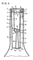
- FIG. 4 The basic construction of the dosing device shown in FIG. 4 corresponds to the dosing device according to FIGS. 1 to 3, and corresponding parts are therefore identified by the same reference numerals.
- This metering device is inserted into a bottle 1 'with an elongated neck, for example a plastic bottle with relatively easily deformable walls.
- the lower end of the channel 18 in the figure is closed with a plate 21 which is fastened to the lower surface of the wall 10, for example by welding or gluing.
- this plate there is an inlet opening 20 coaxially with respect to the channel 18, the diameter of which is approximately 1/4 of the diameter of the region of the channel 18 adjoining the plate, this region beginning in the drawing behind the input curvature of the channel 18.
- This narrowed inlet opening 20 of the channel 18 accelerates, as already mentioned above, the filling of the metering channel 16 when using the metering device in easily deformable containers and / or when metering liquids whose viscosity is greater than that of water.
- a further deviation of the metering device according to FIG. 4 compared to the metering device according to FIGS. 1 to 3 is that small ventilation openings 22 are provided in the wall 14 in the area between the mouth opening 19 of the channel 18 and the annular space 15. These ventilation openings facilitate the entry of air into the metering channel 16 when a liquid whose viscosity is greater than that of water flows out of the metering channel 16 into the collecting space 12. This accelerates the emptying of the metering channel, while in the absence of these ventilation openings due to the viscosity the liquid, the air could possibly not pass through the annular space 15 quickly enough.
Landscapes
- Physics & Mathematics (AREA)
- Fluid Mechanics (AREA)
- General Physics & Mathematics (AREA)
- Closures For Containers (AREA)
- Sampling And Sample Adjustment (AREA)
- Containers And Packaging Bodies Having A Special Means To Remove Contents (AREA)
- Infusion, Injection, And Reservoir Apparatuses (AREA)
Claims (9)
Priority Applications (1)
| Application Number | Priority Date | Filing Date | Title |
|---|---|---|---|
| AT82102249T ATE23639T1 (de) | 1981-03-24 | 1982-03-19 | Rohrfoermige dosiereinrichtung zur abgabe von fluessigkeitsmengen gleichen volumens. |
Applications Claiming Priority (4)
| Application Number | Priority Date | Filing Date | Title |
|---|---|---|---|
| DE3111503 | 1981-03-24 | ||
| DE3111503 | 1981-03-24 | ||
| DE19813150464 DE3150464A1 (de) | 1981-03-24 | 1981-12-19 | Rohrfoermige dosiereinrichtung zur abgabe von fluessigkeitsmengen gleichen volumens |
| DE3150464 | 1981-12-19 |
Publications (3)
| Publication Number | Publication Date |
|---|---|
| EP0061164A2 EP0061164A2 (fr) | 1982-09-29 |
| EP0061164A3 EP0061164A3 (en) | 1984-11-28 |
| EP0061164B1 true EP0061164B1 (fr) | 1986-11-12 |
Family
ID=25792084
Family Applications (1)
| Application Number | Title | Priority Date | Filing Date |
|---|---|---|---|
| EP82102249A Expired EP0061164B1 (fr) | 1981-03-24 | 1982-03-19 | Appareil doseur tubulaire pour délivrer des quantités identiques de fluide |
Country Status (3)
| Country | Link |
|---|---|
| EP (1) | EP0061164B1 (fr) |
| AT (1) | ATE23639T1 (fr) |
| DE (2) | DE3150464A1 (fr) |
Families Citing this family (3)
| Publication number | Priority date | Publication date | Assignee | Title |
|---|---|---|---|---|
| FR2548142B1 (fr) * | 1983-06-30 | 1986-10-31 | Colgate Palmolive Co | Dispositif doseur pour produits liquides conditionnes dans des flacons ou recipients similaires |
| DE3326025C2 (de) * | 1983-07-20 | 1987-03-19 | Weener Plastik Gmbh & Co Kg, 2952 Weener | Gerät zur dosierten Ausgabe von Flüssigkeit |
| WO2012031349A1 (fr) * | 2010-09-06 | 2012-03-15 | Eugene Druyan | Récipient pour distribution de doses de liquide |
Family Cites Families (5)
| Publication number | Priority date | Publication date | Assignee | Title |
|---|---|---|---|---|
| FR1070404A (fr) * | 1949-12-06 | 1954-07-26 | Doseur de liquides | |
| DE1202672B (de) * | 1963-12-04 | 1965-10-07 | Friedrich Stuebbe | Dosiereinrichtung zum Ausschenken von Fluessigkeitsmengen gleichen Volumens aus Fluessigkeitsbehaeltern |
| GB1302677A (fr) * | 1970-09-23 | 1973-01-10 | ||
| IT1045880B (it) * | 1973-03-27 | 1980-06-10 | Guala R E C S A S | Tappo dosatore per bottiglie |
| US4183450A (en) * | 1976-10-06 | 1980-01-15 | Neil Hugh Downing | Metering device |
-
1981
- 1981-12-19 DE DE19813150464 patent/DE3150464A1/de not_active Withdrawn
-
1982
- 1982-03-19 AT AT82102249T patent/ATE23639T1/de not_active IP Right Cessation
- 1982-03-19 EP EP82102249A patent/EP0061164B1/fr not_active Expired
- 1982-03-19 DE DE8282102249T patent/DE3274296D1/de not_active Expired
Also Published As
| Publication number | Publication date |
|---|---|
| EP0061164A2 (fr) | 1982-09-29 |
| DE3274296D1 (en) | 1987-01-02 |
| DE3150464A1 (de) | 1982-12-16 |
| ATE23639T1 (de) | 1986-11-15 |
| EP0061164A3 (en) | 1984-11-28 |
Similar Documents
| Publication | Publication Date | Title |
|---|---|---|
| DE10112332C1 (de) | Tropfkappe zum Ausdosieren von Flüssigkeit in Tropfenform und Behälter mit Tropfkappe | |
| DE3422964A1 (de) | Messvorrichtung fuer fluessigkeiten | |
| DE7409960U (de) | Vorrichtung zum entleeren von fluessigkeit aus einer flasche | |
| DE69205001T2 (de) | Dosiervorrichtung fur flussigkeiten. | |
| DE3326025A1 (de) | Geraet zur dosierten ausgabe von fluessigkeit | |
| EP1451070B1 (fr) | Contenant pour stocker et verser des liquides | |
| DE2262384C3 (de) | Spender für die bemessene Abgabe von pulverförmigem Material oder dergleichen | |
| EP0061164B1 (fr) | Appareil doseur tubulaire pour délivrer des quantités identiques de fluide | |
| AT398299B (de) | Giesseinsatzelement | |
| CH435556A (de) | Tropfeinsatz für einen Behälter | |
| EP0175256B1 (fr) | Doseur tubulaire avec deux chambres pour fluide | |
| DE2752669A1 (de) | Dosierer fuer fluessigkeiten | |
| EP0753131B1 (fr) | Doseur a deux chambres, a regulateur des quantites a doser integre et a fermeture etanche, et son utilisation | |
| EP3838840B1 (fr) | Adaptateur | |
| DE1657199A1 (de) | Mehrkammerbehaelter zur dosierten Abgabe mehrerer Fluessigkeiten | |
| DE3522807A1 (de) | Rohrfoermige dosiervorrichtung zur abgabe von fluessigkeitsmengen gleichen volumens | |
| DE924918C (de) | Geraet zur Ausgabe abgemessener Mengen von Fluessigkeiten | |
| DE2834095C2 (de) | Vorrichtung zur dosierten Abgabe von Flüssigkeiten, insbesondere Konzentraten oder Sirupen zur Getränkeherstellung | |
| DE1293051B (de) | Tropf- oder Giesseinsatz fuer Flaschen und aehnliche Fluessigkeitsbehaelter | |
| CH482597A (de) | Batterietank für Flüssigkeiten, insbesondere für Heizöl | |
| DE3132510C2 (fr) | ||
| DE1264982B (de) | Giessverschluss | |
| WO2001036921A1 (fr) | Bouteille compressible presentant une chambre de dosage | |
| DE9411522U1 (de) | Dosierer | |
| CH671943A5 (fr) |
Legal Events
| Date | Code | Title | Description |
|---|---|---|---|
| PUAI | Public reference made under article 153(3) epc to a published international application that has entered the european phase |
Free format text: ORIGINAL CODE: 0009012 |
|
| AK | Designated contracting states |
Designated state(s): AT BE CH DE FR GB IT NL |
|
| PUAL | Search report despatched |
Free format text: ORIGINAL CODE: 0009013 |
|
| AK | Designated contracting states |
Designated state(s): AT BE CH DE FR GB IT LI NL |
|
| 17P | Request for examination filed |
Effective date: 19841114 |
|
| 17Q | First examination report despatched |
Effective date: 19860130 |
|
| GRAA | (expected) grant |
Free format text: ORIGINAL CODE: 0009210 |
|
| AK | Designated contracting states |
Kind code of ref document: B1 Designated state(s): AT BE CH DE FR GB IT LI NL |
|
| PG25 | Lapsed in a contracting state [announced via postgrant information from national office to epo] |
Ref country code: NL Effective date: 19861112 Ref country code: BE Effective date: 19861112 |
|
| REF | Corresponds to: |
Ref document number: 23639 Country of ref document: AT Date of ref document: 19861115 Kind code of ref document: T |
|
| ET | Fr: translation filed | ||
| REF | Corresponds to: |
Ref document number: 3274296 Country of ref document: DE Date of ref document: 19870102 |
|
| ITF | It: translation for a ep patent filed | ||
| PG25 | Lapsed in a contracting state [announced via postgrant information from national office to epo] |
Ref country code: AT Effective date: 19870319 |
|
| PG25 | Lapsed in a contracting state [announced via postgrant information from national office to epo] |
Ref country code: LI Effective date: 19870331 Ref country code: CH Effective date: 19870331 |
|
| NLV1 | Nl: lapsed or annulled due to failure to fulfill the requirements of art. 29p and 29m of the patents act | ||
| PLBE | No opposition filed within time limit |
Free format text: ORIGINAL CODE: 0009261 |
|
| STAA | Information on the status of an ep patent application or granted ep patent |
Free format text: STATUS: NO OPPOSITION FILED WITHIN TIME LIMIT |
|
| 26N | No opposition filed | ||
| REG | Reference to a national code |
Ref country code: CH Ref legal event code: PL |
|
| PGFP | Annual fee paid to national office [announced via postgrant information from national office to epo] |
Ref country code: FR Payment date: 19900327 Year of fee payment: 9 |
|
| ITTA | It: last paid annual fee | ||
| PGFP | Annual fee paid to national office [announced via postgrant information from national office to epo] |
Ref country code: GB Payment date: 19900331 Year of fee payment: 9 |
|
| PG25 | Lapsed in a contracting state [announced via postgrant information from national office to epo] |
Ref country code: GB Effective date: 19910319 |
|
| GBPC | Gb: european patent ceased through non-payment of renewal fee | ||
| PG25 | Lapsed in a contracting state [announced via postgrant information from national office to epo] |
Ref country code: FR Effective date: 19911129 |
|
| REG | Reference to a national code |
Ref country code: FR Ref legal event code: ST |
|
| PGFP | Annual fee paid to national office [announced via postgrant information from national office to epo] |
Ref country code: DE Payment date: 19980519 Year of fee payment: 17 |
|
| PG25 | Lapsed in a contracting state [announced via postgrant information from national office to epo] |
Ref country code: DE Free format text: LAPSE BECAUSE OF NON-PAYMENT OF DUE FEES Effective date: 20000101 |