EP0061166A2 - Dispositif de traitement au jet abrasif pour enceinte de travail sous pression - Google Patents
Dispositif de traitement au jet abrasif pour enceinte de travail sous pression Download PDFInfo
- Publication number
- EP0061166A2 EP0061166A2 EP82102253A EP82102253A EP0061166A2 EP 0061166 A2 EP0061166 A2 EP 0061166A2 EP 82102253 A EP82102253 A EP 82102253A EP 82102253 A EP82102253 A EP 82102253A EP 0061166 A2 EP0061166 A2 EP 0061166A2
- Authority
- EP
- European Patent Office
- Prior art keywords
- blasting
- pressure medium
- valve
- hose
- control valve
- Prior art date
- Legal status (The legal status is an assumption and is not a legal conclusion. Google has not performed a legal analysis and makes no representation as to the accuracy of the status listed.)
- Granted
Links
Images
Classifications
-
- B—PERFORMING OPERATIONS; TRANSPORTING
- B24—GRINDING; POLISHING
- B24C—ABRASIVE OR RELATED BLASTING WITH PARTICULATE MATERIAL
- B24C7/00—Equipment for feeding abrasive material; Controlling the flowability, constitution, or other physical characteristics of abrasive blasts
- B24C7/0046—Equipment for feeding abrasive material; Controlling the flowability, constitution, or other physical characteristics of abrasive blasts the abrasive material being fed in a gaseous carrier
- B24C7/0069—Equipment for feeding abrasive material; Controlling the flowability, constitution, or other physical characteristics of abrasive blasts the abrasive material being fed in a gaseous carrier with means for preventing clogging of the equipment or for preventing abrasive entering the airway
Definitions
- the invention relates to a pressure chamber blasting device consisting of a blasting agent container with a blasting agent filling opening which can be closed by means of a cone and a blasting nozzle connected to the blasting agent container by means of a blasting hose, the blasting agent container and the blasting hose being connected to a compressed air source via a pressure medium control valve and the closing cone in the pressure medium supply line leading into the container is guided such that it is actuated in the closing direction by the inflowing pressure medium.
- the known pressure chamber blasting devices have proven to be very effective in that good blasting results are achieved with their help.
- the blasting agent container remains under pressure after the pressure medium control valve is closed and the pressure relief or venting until the air stored in the blasting agent container is completely blown off after the control valve designed as a two-way valve is switched off the blasting hose or via the blasting nozzle is possible with the subsequent blasting of blasting media.
- the aim of the present invention is to provide a pressure chamber jet device of the type described, in which the pressure relief of the container and the pressure medium lines takes place automatically and the invention consists in that a three-way valve is provided as the control valve.
- the invention provides a pressure chamber blasting device in which, at the same time as the pressure medium flow is blocked, the container is vented by automatically opening the container to the atmosphere via the pressure medium supply line, which now serves as the ventilation line, and the R port of the control valve.
- the vent valve attached to the boiler can therefore be omitted, all the required functions are controlled in one valve.
- Another significant advantage of the pressure chamber blasting device according to the invention can also be seen in the fact that the pressure relief does not take place directly via a valve that opens directly to the atmosphere, but via the closing cone guide located in the dome of the container, through which no or at most a negligibly small amount of wear-causing Abrasives are carried away to the outside.
- the control valve is formed by a mechanical, rotary lever-operated three-way ball valve with four housing connections, of which one connection to the boiler on the one hand and lead to the blasting hose on the other hand, while one of the two remaining connections serves as a vent connection and is expediently provided with a quick-release coupling for attaching a sound-stop vent cartridge.
- Venting cartridge as a result of the resulting closure of the vent opening, an additional valve position can be achieved in which the entire amount of air fed in - for example for the purpose of blowing the container through for cleaning purposes - can be guided into the boiler by blocking the connection leading to the blasting hose.
- a two-way / three-way valve pneumatically controlled by a two / three-way valve as a pushbutton is provided as the pressure-medium control valve, which controls a common pressure-medium line leading both to the blasting agent container and to the blasting hose, a water separator being arranged between the pressure medium control valve and the container is.
- the pressure chamber blasting device designed in this way fulfills all technical and safety requirements for such a device insofar as not only the device is automatically vented at the same time as the pressure medium flow is blocked, but the entire pressure medium and blasting medium control from the blasting nozzle takes place in the Way that the pressure medium control valve is reversed as soon as the button is closed, thereby relieving pressure via the pressure medium line.
- the water separator downstream of the pressure control valve serves as a special advantage in this air flow direction as a self-cleaning dust filter, by means of which both the pressure control valve and the atmosphere are reliably protected from any type of entrained dust or blasting agent, and this immediately when the blasting process is resumed through the container or compressed air flowing into the blasting hose is cleaned by backwashing.
- the water separator is expediently arranged in the pressure medium line between the pressure medium control valve and the line branch, wherein a non-return valve is arranged in the line leading to the blasting hose as far as possible before it flows into the blasting hose - ie immediately behind the branch.
- the check valve itself is thereby protected against wear, and the water separator, which acts as a filter in this operating phase, is also protected against overload by an excessive amount of blasting medium flowing back.
- the blasting agent entrained in the blasting hose with the refluxing air is therefore only returned to the container and held back by the blasting agent column, whereby blasting agent entrained from the blasting agent column or entrained dust particles are essentially retained at the closing cone of the container filling opening. Any fine dust that is entrained is then filtered out in the water separator.
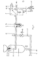
- 1 denotes the blasting agent container of a pressure chamber blasting device, which is provided with a blasting agent filling opening 3 which can be closed by means of the closing key 2 and a blasting nozzle (not shown) connected to the blasting agent container 1 by means of blasting hose 4, the blasting agent container 1 and the blasting hose 4 being provided via a pressure medium control valve are connected to a compressed air source and the closing cone 2 is guided in the pressure medium supply line 6 leading into the container such that it is separated from the inflowing pressure medium in Closing direction is operated.
- the pressure medium control valve 5 is formed by a pneumatically controlled two / three-way valve, which is arranged by means of a two / three-way valve as a button 7 arranged on the blasting nozzle and which both the line 6 leading to the blasting agent container and the line 8 leading to the blasting hose controls that are led to the branch 10 in a common line q .
- a water separator 9 is arranged between the pressure medium valve 5 and the container 1. The water separator 9 is arranged in the pressure medium line between the pressure medium control valve and the branching 10 of the lines 6, 8, a check valve 12 being arranged in the line 8 leading to the blasting hose 4 immediately behind the branching 10.
- the Druckweq is released from the compressor feed line 13 to the Z connection of the pressure medium control valve, whereby the pressure chamber jet device is pressurized with compressed air by closing the R connection and opening the pressure medium path from P to A of this valve.
- the closing cone 2 is raised, thus closing the blasting agent filling opening 3 and consequently building up pressure in the container 1, the check valve 12 is opened at the same time as the pressure builds up, and the pressure medium path is released into the blasting hose, into which the blasting medium comes out of the container 1 is fed into the mouth 11 under the pressure building up there.
- the separator 9 acts as a water separator, at the sintering insert 9a of which the moisture introduced with the air condenses, which drips into the bottom of the separator and can be removed from time to time via the bottom valve.
- the P connection of the pressure medium control valve 5 is closed and its R connection is opened to A, whereby the entire device is opened to the atmosphere.
- the check valve 12 is first closed, thereby preventing the air from flowing back via the line 8 and, in particular, from the blasting hose 4 flowing back beyond the valve. Rather, the pressure medium and blasting medium return flow takes place completely via the container 1, in which the blasting medium flowing back from the blasting hose 4 is collected. Any entrained items from the abrasive column Abrasives and entrained dust particles primarily catch on the closing cone 2 and fall back into the container. Residual dust quantities passing into the line 6 are caught in the sintering insert 9a of the water separator 9, which acts as a dust filter in this phase. The valve 5 and the atmosphere are completely protected against dust.
- the sintered insert of the water separator 9 is automatically cleaned of the collected dust again in the manner of a backwash filter.
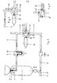
- control valve is a mechanical three-way ball valve 18 with four connections 13, 15, which is actuated by means of a pivoting lever 14 , 16, 17 formed, of which the connection 13 serves to connect to the compressor (not shown), the two mutually opposite connections 15, 16 serve to connect to the boiler (connection 15) or blasting hose (connection 16), during the Connection 17 serves as a vent connection, which is provided with a quick-release coupling 19 for attaching a sound stop vent cartridge 20.
- a water separator 9, 9a is provided between the three-way ball valve 18 and the blasting agent container 1, but in this embodiment provided with a mechanical control it is also unnecessary or can be arranged elsewhere, for example between the compressor and the ball valve.
- FIG. 2 first of all creates a simple mechanical single-lever control for pressure chamber blasting units, the arrangement in the operating position being shown in FIG. 2 in which, when the connection 17 is closed, there is a connection from the compressor 13 both to the container and to the blasting hose.
- Fig. 3 shows the closed position in which both the boiler and the blasting hose are simultaneously connected to the atmosphere and are thus relieved of pressure.
- Fig. 4 shows a rinsing position of the ball valve, the effectiveness of which requires the uncoupling of the cartridge 20 and thus the automatic closing of the quick-release coupling 19. In this case, the entire inflowing air is passed over the container with the jet hose line 8 closed.
Landscapes
- Engineering & Computer Science (AREA)
- Mechanical Engineering (AREA)
- Cleaning In General (AREA)
- Spray Control Apparatus (AREA)
- Forklifts And Lifting Vehicles (AREA)
- Knitting Machines (AREA)
- Air Bags (AREA)
- Filling Or Discharging Of Gas Storage Vessels (AREA)
- Electrical Discharge Machining, Electrochemical Machining, And Combined Machining (AREA)
- Polishing Bodies And Polishing Tools (AREA)
- Processing Of Meat And Fish (AREA)
- Safety Valves (AREA)
- Dental Tools And Instruments Or Auxiliary Dental Instruments (AREA)
- Analysing Materials By The Use Of Radiation (AREA)
Priority Applications (1)
| Application Number | Priority Date | Filing Date | Title |
|---|---|---|---|
| AT82102253T ATE15004T1 (de) | 1981-03-24 | 1982-03-19 | Druckkammerstrahlgeraet. |
Applications Claiming Priority (2)
| Application Number | Priority Date | Filing Date | Title |
|---|---|---|---|
| DE3111581 | 1981-03-24 | ||
| DE19813111581 DE3111581A1 (de) | 1981-03-24 | 1981-03-24 | Druckkammerstrahlgeraet |
Publications (3)
| Publication Number | Publication Date |
|---|---|
| EP0061166A2 true EP0061166A2 (fr) | 1982-09-29 |
| EP0061166A3 EP0061166A3 (en) | 1982-10-27 |
| EP0061166B1 EP0061166B1 (fr) | 1985-08-21 |
Family
ID=6128159
Family Applications (1)
| Application Number | Title | Priority Date | Filing Date |
|---|---|---|---|
| EP82102253A Expired EP0061166B1 (fr) | 1981-03-24 | 1982-03-19 | Dispositif de traitement au jet abrasif pour enceinte de travail sous pression |
Country Status (5)
| Country | Link |
|---|---|
| EP (1) | EP0061166B1 (fr) |
| AT (1) | ATE15004T1 (fr) |
| DE (1) | DE3111581A1 (fr) |
| DK (1) | DK169205B1 (fr) |
| FI (1) | FI72448C (fr) |
Cited By (4)
| Publication number | Priority date | Publication date | Assignee | Title |
|---|---|---|---|---|
| EP0201145A1 (fr) * | 1985-05-07 | 1986-11-12 | Rijndelta Coating Technieken B.V. | Dispositif de sablage |
| WO1991000164A1 (fr) * | 1989-06-24 | 1991-01-10 | Sigrid Keizers | Dispositif de sablage avec des granules abrasifs humides |
| EP0530154A3 (en) * | 1991-06-19 | 1993-04-07 | C.I.E. Dentalfarm S.R.L. | A microsanding system and a pneumatic valve used in the system |
| DE19521051A1 (de) * | 1995-06-09 | 1996-12-12 | Woma Maasberg Co Gmbh W | Hochdruckwasserstrahlbearbeitungseinrichtung |
Families Citing this family (1)
| Publication number | Priority date | Publication date | Assignee | Title |
|---|---|---|---|---|
| DE3939420C2 (de) * | 1989-11-29 | 1995-06-22 | Neubauer Geb Costas Perez Merc | Verfahren und Vorrichtung zum Schneiden widerstandsfähiger Werkstoffe mit einem Wasserstrahl |
Family Cites Families (9)
| Publication number | Priority date | Publication date | Assignee | Title |
|---|---|---|---|---|
| BE409758A (fr) * | ||||
| US1171286A (en) * | 1912-04-22 | 1916-02-08 | Howard L Wadsworth | Sand-blast machine. |
| US2729917A (en) * | 1953-06-30 | 1956-01-10 | William C Gregory | Cleaning apparatus |
| US3034263A (en) * | 1959-08-07 | 1962-05-15 | Ruric N Mcdaniel | Sand blasting apparatus |
| US3084484A (en) * | 1960-11-17 | 1963-04-09 | Sylvania Electric Prod | Pneumatic abrasive cutting apparatus |
| US3148484A (en) * | 1963-01-15 | 1964-09-15 | Jaroco Internat Inc | Sandblast generator |
| FR1515965A (fr) * | 1966-03-31 | 1968-06-13 | Sableuse à air comprimé | |
| US3741738A (en) * | 1971-04-12 | 1973-06-26 | Pauli & Griffin Co | Abrasive blasting equipment and self-cleaning abrasive trap therefore |
| US4026072A (en) * | 1976-08-09 | 1977-05-31 | Dremann George H | Self-cleaning muffler for an abrasive blast system |
-
1981
- 1981-03-24 DE DE19813111581 patent/DE3111581A1/de active Granted
-
1982
- 1982-03-17 DK DK117882A patent/DK169205B1/da not_active IP Right Cessation
- 1982-03-19 EP EP82102253A patent/EP0061166B1/fr not_active Expired
- 1982-03-19 AT AT82102253T patent/ATE15004T1/de not_active IP Right Cessation
- 1982-03-23 FI FI821011A patent/FI72448C/fi not_active IP Right Cessation
Cited By (5)
| Publication number | Priority date | Publication date | Assignee | Title |
|---|---|---|---|---|
| EP0201145A1 (fr) * | 1985-05-07 | 1986-11-12 | Rijndelta Coating Technieken B.V. | Dispositif de sablage |
| WO1991000164A1 (fr) * | 1989-06-24 | 1991-01-10 | Sigrid Keizers | Dispositif de sablage avec des granules abrasifs humides |
| EP0530154A3 (en) * | 1991-06-19 | 1993-04-07 | C.I.E. Dentalfarm S.R.L. | A microsanding system and a pneumatic valve used in the system |
| DE19521051A1 (de) * | 1995-06-09 | 1996-12-12 | Woma Maasberg Co Gmbh W | Hochdruckwasserstrahlbearbeitungseinrichtung |
| DE19521051C2 (de) * | 1995-06-09 | 1998-04-09 | Woma Maasberg Co Gmbh W | Hochdruckwasserstrahlbearbeitungseinrichtung |
Also Published As
| Publication number | Publication date |
|---|---|
| DK117882A (da) | 1982-09-25 |
| FI72448B (fi) | 1987-02-27 |
| DE3111581C2 (fr) | 1987-11-12 |
| EP0061166A3 (en) | 1982-10-27 |
| ATE15004T1 (de) | 1985-09-15 |
| EP0061166B1 (fr) | 1985-08-21 |
| FI821011A0 (fi) | 1982-03-23 |
| DK169205B1 (da) | 1994-09-12 |
| FI72448C (fi) | 1987-06-08 |
| FI821011L (fi) | 1982-09-25 |
| DE3111581A1 (de) | 1982-10-14 |
Similar Documents
| Publication | Publication Date | Title |
|---|---|---|
| DE4425863C2 (de) | Saug- und Blasvorrichtung | |
| DE2724318C2 (de) | Verfahren zum Befeuchten des Strahlmittels beim Druckluftstrahlen | |
| EP1346700A1 (fr) | Pièce a main à jet abrasif pour un appareil dentaire avec filtre protecteur | |
| DE102014009231A1 (de) | Absperr-Filtervorrichtung | |
| EP0061166A2 (fr) | Dispositif de traitement au jet abrasif pour enceinte de travail sous pression | |
| DE848552C (de) | Mit Pressgas arbeitender Staubsauger | |
| DE2746037A1 (de) | Hochdruckreinigungsgeraet | |
| DE19613967A1 (de) | Vorrichtung zur Sprühbeschichtung | |
| DE3239429A1 (de) | Verfahren und vorrichtung zum betreiben eines hochdruckstrahlers | |
| DE3403197C2 (fr) | ||
| DE7240741U (de) | Spritzeinrichtung, wie Spritzpistolen und dergleichen mit Loslaß-Abschaltung | |
| DE69716693T2 (de) | Steuerungsvorrichtung für eine Reinigungsvorrichtung für verseuchte Oberflächen | |
| DE4101248C2 (de) | Strömungsventil | |
| DE19516740C2 (de) | Vakuumtoilettensystem | |
| DE3214764A1 (de) | Vorrichtung zum strahlen feinwerktechnischer werkstuecke | |
| DE1813089A1 (de) | Vorrichtung zum Beaufschlagen eines beweglichen,flexiblen Bauwerks | |
| DE3801913A1 (de) | Verfahren und vorrichtung zur adsorption bzw. chemiesorption von gasfoermigen bestandteilen aus einem gasstrom | |
| DE693764C (de) | Vorrichtung zum Unschaedlichmachen von Gesteinsbohrstaub | |
| DE102006009965B4 (de) | Absaug-Anlage für eine spanabhebende Bearbeitungs-Maschine | |
| DE19823085C1 (de) | Flachstrahldüse | |
| DE19546042C1 (de) | Druckstrahlgerät zum Reinigen von Oberflächen mit einer Einrichtung zum Reinigen eines Schutzvisiers der Bedienungsperson | |
| DE29619975U1 (de) | Sprühvorrichtung zum flächigen Auftragen von Flüssigkeiten | |
| DE492990C (de) | Spritzvorrichtung | |
| EP0337936A1 (fr) | Station pour eau domestique | |
| DE8912098U1 (de) | Inhalator |
Legal Events
| Date | Code | Title | Description |
|---|---|---|---|
| PUAI | Public reference made under article 153(3) epc to a published international application that has entered the european phase |
Free format text: ORIGINAL CODE: 0009012 |
|
| PUAL | Search report despatched |
Free format text: ORIGINAL CODE: 0009013 |
|
| AK | Designated contracting states |
Designated state(s): AT BE CH FR IT SE |
|
| AK | Designated contracting states |
Designated state(s): AT BE CH FR IT SE |
|
| 17P | Request for examination filed |
Effective date: 19821217 |
|
| ITF | It: translation for a ep patent filed | ||
| GRAA | (expected) grant |
Free format text: ORIGINAL CODE: 0009210 |
|
| AK | Designated contracting states |
Designated state(s): AT BE CH FR IT LI SE |
|
| REF | Corresponds to: |
Ref document number: 15004 Country of ref document: AT Date of ref document: 19850915 Kind code of ref document: T |
|
| ET | Fr: translation filed | ||
| PLBE | No opposition filed within time limit |
Free format text: ORIGINAL CODE: 0009261 |
|
| STAA | Information on the status of an ep patent application or granted ep patent |
Free format text: STATUS: NO OPPOSITION FILED WITHIN TIME LIMIT |
|
| 26N | No opposition filed | ||
| ITTA | It: last paid annual fee | ||
| EAL | Se: european patent in force in sweden |
Ref document number: 82102253.0 |
|
| PGFP | Annual fee paid to national office [announced via postgrant information from national office to epo] |
Ref country code: AT Payment date: 19980330 Year of fee payment: 17 |
|
| PGFP | Annual fee paid to national office [announced via postgrant information from national office to epo] |
Ref country code: SE Payment date: 19990315 Year of fee payment: 18 Ref country code: CH Payment date: 19990315 Year of fee payment: 18 |
|
| PG25 | Lapsed in a contracting state [announced via postgrant information from national office to epo] |
Ref country code: AT Free format text: LAPSE BECAUSE OF NON-PAYMENT OF DUE FEES Effective date: 19990319 |
|
| PGFP | Annual fee paid to national office [announced via postgrant information from national office to epo] |
Ref country code: FR Payment date: 19990330 Year of fee payment: 18 |
|
| PGFP | Annual fee paid to national office [announced via postgrant information from national office to epo] |
Ref country code: BE Payment date: 19990402 Year of fee payment: 18 |
|
| PG25 | Lapsed in a contracting state [announced via postgrant information from national office to epo] |
Ref country code: SE Free format text: LAPSE BECAUSE OF NON-PAYMENT OF DUE FEES Effective date: 20000320 |
|
| PG25 | Lapsed in a contracting state [announced via postgrant information from national office to epo] |
Ref country code: LI Free format text: LAPSE BECAUSE OF NON-PAYMENT OF DUE FEES Effective date: 20000331 Ref country code: CH Free format text: LAPSE BECAUSE OF NON-PAYMENT OF DUE FEES Effective date: 20000331 Ref country code: BE Free format text: LAPSE BECAUSE OF NON-PAYMENT OF DUE FEES Effective date: 20000331 |
|
| BERE | Be: lapsed |
Owner name: BRENNECKE HEINZ Effective date: 20000331 |
|
| EUG | Se: european patent has lapsed |
Ref document number: 82102253.0 |
|
| REG | Reference to a national code |
Ref country code: CH Ref legal event code: PL |
|
| PG25 | Lapsed in a contracting state [announced via postgrant information from national office to epo] |
Ref country code: FR Free format text: LAPSE BECAUSE OF NON-PAYMENT OF DUE FEES Effective date: 20001130 |
|
| REG | Reference to a national code |
Ref country code: FR Ref legal event code: ST |