EP0061171A1 - Dispositif pour couper et dévier une bande de matière fraîchement coulée - Google Patents
Dispositif pour couper et dévier une bande de matière fraîchement coulée Download PDFInfo
- Publication number
- EP0061171A1 EP0061171A1 EP82102276A EP82102276A EP0061171A1 EP 0061171 A1 EP0061171 A1 EP 0061171A1 EP 82102276 A EP82102276 A EP 82102276A EP 82102276 A EP82102276 A EP 82102276A EP 0061171 A1 EP0061171 A1 EP 0061171A1
- Authority
- EP
- European Patent Office
- Prior art keywords
- web
- carriage
- knives
- knife
- machine
- Prior art date
- Legal status (The legal status is an assumption and is not a legal conclusion. Google has not performed a legal analysis and makes no representation as to the accuracy of the status listed.)
- Granted
Links
Images



Classifications
-
- B—PERFORMING OPERATIONS; TRANSPORTING
- B26—HAND CUTTING TOOLS; CUTTING; SEVERING
- B26D—CUTTING; DETAILS COMMON TO MACHINES FOR PERFORATING, PUNCHING, CUTTING-OUT, STAMPING-OUT OR SEVERING
- B26D1/00—Cutting through work characterised by the nature or movement of the cutting member or particular materials not otherwise provided for; Apparatus or machines therefor; Cutting members therefor
- B26D1/01—Cutting through work characterised by the nature or movement of the cutting member or particular materials not otherwise provided for; Apparatus or machines therefor; Cutting members therefor involving a cutting member which does not travel with the work
- B26D1/04—Cutting through work characterised by the nature or movement of the cutting member or particular materials not otherwise provided for; Apparatus or machines therefor; Cutting members therefor involving a cutting member which does not travel with the work having a linearly-movable cutting member
- B26D1/045—Cutting through work characterised by the nature or movement of the cutting member or particular materials not otherwise provided for; Apparatus or machines therefor; Cutting members therefor involving a cutting member which does not travel with the work having a linearly-movable cutting member for thin material, e.g. for sheets, strips or the like
-
- Y—GENERAL TAGGING OF NEW TECHNOLOGICAL DEVELOPMENTS; GENERAL TAGGING OF CROSS-SECTIONAL TECHNOLOGIES SPANNING OVER SEVERAL SECTIONS OF THE IPC; TECHNICAL SUBJECTS COVERED BY FORMER USPC CROSS-REFERENCE ART COLLECTIONS [XRACs] AND DIGESTS
- Y10—TECHNICAL SUBJECTS COVERED BY FORMER USPC
- Y10T—TECHNICAL SUBJECTS COVERED BY FORMER US CLASSIFICATION
- Y10T83/00—Cutting
- Y10T83/202—With product handling means
- Y10T83/2066—By fluid current
-
- Y—GENERAL TAGGING OF NEW TECHNOLOGICAL DEVELOPMENTS; GENERAL TAGGING OF CROSS-SECTIONAL TECHNOLOGIES SPANNING OVER SEVERAL SECTIONS OF THE IPC; TECHNICAL SUBJECTS COVERED BY FORMER USPC CROSS-REFERENCE ART COLLECTIONS [XRACs] AND DIGESTS
- Y10—TECHNICAL SUBJECTS COVERED BY FORMER USPC
- Y10T—TECHNICAL SUBJECTS COVERED BY FORMER US CLASSIFICATION
- Y10T83/00—Cutting
- Y10T83/485—Cutter with timed stroke relative to moving work
- Y10T83/49—Traveling cutter
-
- Y—GENERAL TAGGING OF NEW TECHNOLOGICAL DEVELOPMENTS; GENERAL TAGGING OF CROSS-SECTIONAL TECHNOLOGIES SPANNING OVER SEVERAL SECTIONS OF THE IPC; TECHNICAL SUBJECTS COVERED BY FORMER USPC CROSS-REFERENCE ART COLLECTIONS [XRACs] AND DIGESTS
- Y10—TECHNICAL SUBJECTS COVERED BY FORMER USPC
- Y10T—TECHNICAL SUBJECTS COVERED BY FORMER US CLASSIFICATION
- Y10T83/00—Cutting
- Y10T83/647—With means to convey work relative to tool station
- Y10T83/6584—Cut made parallel to direction of and during work movement
- Y10T83/6592—Interrelated work-conveying and tool-moving means
- Y10T83/6595—With means to move tool laterally of feed direction during cutting
-
- Y—GENERAL TAGGING OF NEW TECHNOLOGICAL DEVELOPMENTS; GENERAL TAGGING OF CROSS-SECTIONAL TECHNOLOGIES SPANNING OVER SEVERAL SECTIONS OF THE IPC; TECHNICAL SUBJECTS COVERED BY FORMER USPC CROSS-REFERENCE ART COLLECTIONS [XRACs] AND DIGESTS
- Y10—TECHNICAL SUBJECTS COVERED BY FORMER USPC
- Y10T—TECHNICAL SUBJECTS COVERED BY FORMER US CLASSIFICATION
- Y10T83/00—Cutting
- Y10T83/647—With means to convey work relative to tool station
- Y10T83/6584—Cut made parallel to direction of and during work movement
- Y10T83/6603—Tool shiftable relative to work-conveying means
-
- Y—GENERAL TAGGING OF NEW TECHNOLOGICAL DEVELOPMENTS; GENERAL TAGGING OF CROSS-SECTIONAL TECHNOLOGIES SPANNING OVER SEVERAL SECTIONS OF THE IPC; TECHNICAL SUBJECTS COVERED BY FORMER USPC CROSS-REFERENCE ART COLLECTIONS [XRACs] AND DIGESTS
- Y10—TECHNICAL SUBJECTS COVERED BY FORMER USPC
- Y10T—TECHNICAL SUBJECTS COVERED BY FORMER US CLASSIFICATION
- Y10T83/00—Cutting
- Y10T83/869—Means to drive or to guide tool
- Y10T83/8736—Sequential cutting motions
-
- Y—GENERAL TAGGING OF NEW TECHNOLOGICAL DEVELOPMENTS; GENERAL TAGGING OF CROSS-SECTIONAL TECHNOLOGIES SPANNING OVER SEVERAL SECTIONS OF THE IPC; TECHNICAL SUBJECTS COVERED BY FORMER USPC CROSS-REFERENCE ART COLLECTIONS [XRACs] AND DIGESTS
- Y10—TECHNICAL SUBJECTS COVERED BY FORMER USPC
- Y10T—TECHNICAL SUBJECTS COVERED BY FORMER US CLASSIFICATION
- Y10T83/00—Cutting
- Y10T83/869—Means to drive or to guide tool
- Y10T83/8748—Tool displaceable to inactive position [e.g., for work loading]
- Y10T83/8749—By pivotal motion
Definitions
- This invention relates, generally, to the production of thin films and, more particularly, to a semiautomatic apparatus for cutting and diverting a continuously advancing, freshly cast web'without loss of web-forwarding tension.
- film is produced by extruding a web of molten, polymeric, film-forming materials onto a quench wheel and then advancing the web through stretching and slitting stations to one or more windups.
- the cast, unoriented web is led manually under the quench wheel and over rolls located adjacent the quench wheel. From those rolls, it is guided through a slot in the floor to a waste accumulator.
- a manual traversing knife is inserted through the web adjacent one of its sides to form a strip which is then cut to form a leader. When that leader has been threaded through the stretching stations to another waste collector, the traversing knife is moved across the web, thereby transferring it to the production thread-path.
- the stretched, oriented film is routed through the slitting station to the windups.
- the quenched web can be re-routed to the waste accumulator by first cutting a leader, guiding it to waste and then traversing the knife through the web.
- an operator uses scissors to cut a leading edge across the tough, thick, unoriented, amorphous, cast web and then must manipulate that leading edge through the slot to the waste accumulator. Forwarding tension is lost when the web is cut. The time required to accomplish this operation safely places a limit on the maximum throughput for the entire machine.
- the potential throughput of a machine for manufacturing film has been increased substantially by the provision of a semiautomatic apparatus for cutting and diverting a freshly cast web in its advance from a quench wheel to a stretching station.
- the apparatus includes a carriage mounted for movement toward and away from the path of the web and a drive for moving the carriage.
- a pair of knives are mounted on the carriage for pivotal movement into the web and for traversing movement in opposite directions through its width to cut a leader.
- the machine into which the apparatus of this invention has been incorporated includes a die 10 from which a web 12 of molten polymer is extruded and cast onto a quench wheel 14. Web 12 is stripped from wheel 14 and guided over support rolls 16, 18, through a gauge 20 for measuring web thickness and past a manually operated, traversing knife 22 to a roll 24. The web then advances over a roll 26 to a stretching station 28 where it is orientation drawn in the machine direction (MD). At a subsequent stretching station, the web is drawn in the transverse direction (TD). Then, in normal production, the resulting thin film is advanced through a slitting station to multiple windups.
- MD machine direction
- TD transverse direction
- the apparatus of the invention includes a carriage 30 slidably mounted on guides 32 located on opposite sides of the path of advance for web 12; the guide on the right hand (RH) side of the machine appears in Fig. 1.
- Roll 26 is rotatably mounted on carriage 30.
- a pair of knives 34, 36 are mounted for pivotal movement into the path of web 12 and for rotation about their axes. Each knife is carried by a traversing block; the block for left hand (LH) knife 36 appears at 38 in Fig. 1.
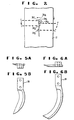
- the manner in which the knives 34, 36 are traversed in opposite directions from a home position adjacent the center of the web 12 is shown in Figs. 2 and 4.
- actuators for knives 34, 36 and a roll 40 are energized by signals from the logic unit in a programmed controller.
- an unplanned stoppage is initiated automatically by the detection of a break in the web at MD stretching station 28.
- Roll 40 is swung into a nipping engagement with roll 26 and knives 34, 36 cut a tongue from web 12. That tongue is diverted to a chute 42 by a jet device 43 and guided between a pair of rolls 44, 45 by air streams in the chute.
- the air streams are introduced through slot jets 46, 47. Excess air is exhausted through a vaned opening 48 and a Coanda surface is provided between slot jet 46 and opening 48.
- actuators move the rolls 44, 45 into nipping engagement and the tongue is delivered to a waste shredder.
- knives 34, 36 have travelled through the edges of the web and are returned to their home positions.
- the full width of web 12 is advanced to waste by nip rolls 44, 45; the trailing end of the cut length is exhausted into the aisle between carriage 30 and MD stretching station 28.
- Web-forwarding tension is retained on both lengths, throughout the cut-and-divert cycle, by rolls 26, 40, 44, 45.
- Figs. 3 and 4 Structural arrangements and relationships in a useful embodiment of the apparatus are shown in Figs. 3 and 4.
- Guides 32 are attached to upright frame members 49 located at the sides of the machine and receive bushings 50 that are carried by side plates 52 of carriage 30.
- Each side plate 52 also carries an internally threaded follower 54 that receives an upright drive screw 56.
- Screws 56 are driven through a gear box on a horizontal frame member atop frame members 49 and operate to raise and lower the carriage between the positions shown in Fig. 1.
- the carriage can be locked in the raised position, during startup, by pinning an ear 58 to a similar ear on the horizontal frame member.
- Roll 26 is supported by bearings in a flange block 60 and is driven through a coupling 62 by a speed reducer and motor mounted on the LH side plate 52.
- Air jet assembly 43 includes a pair of plates 64, 65 that are bracketed to the mount for a motor 66.
- Plate 64 has an elongated plenum 68 that is connected to a valved source of air under pressure and discharges to a slot jet defined by a groove milled into the adjacent face of plate 65. The jet is directed'at the path of advance of web 12.
- Motor 66 is coupled to a sprocket wheel 69 through a chain.
- Wheel 69 is coupled to a LH screw 70 and a RH screw 72.
- the inner ends of screws 70, 72 are supported by bearings located in a box 74 and the outer ends by bearings 75 mounted on side plates 52 of carriage 30.
- Box 74 is bracketed at the Did-points of guide shafts 76, 77 for LH and RH traversing blocks 38, 78.
- Blocks 38, 78 carry bushings 79 that receive shafts 76, 77 and, between the bushings, internally threaded sleeves 80, 82 that receive the screws 70, 72. In this manner, blocks 38, 78 are traversed to-and-fro the home positions of knives 36, 34.
- LH knife 36 is fastened to the bottom end of a holder 84 that is round in a mid-length 85 (Fig. 4).
- Length 85 is rotatable in a bore that extends through a bar 86.
- a follower 88 that travels in an elongated cam 90 as block 38 is traversed.
- Cam 90 is attached to a part on the frame.
- bar 86 is attached rigidly to another bar 92 which is pivoted at 94 between the spaced ears of a mounting bracket 96 carried by block 38.
- bar 92 is pivotally attached to the rod of an actuator 98.
- the other end of actuator 98 is pivoted to a bracket attached to the top of block 38.
- RH knife 34 is mounted and actuated in the same manner as knife 36 except that its mounting bracket 104 is disposed at angles slightly divergent from parallelism with planes in and perpendicular to the normal path of travel for web 12, i.e., the mount for knife 34 is tilted about two axes.
- the cutting edge of knife 34 is slightly to the left of knife 36 when both are in the home positions 34h, 36h (Fig. 2).
- Another factor bearing on the position of the cutting edge of knife 34 when in the home position is its relative length (Figs. 58 and 6B).
- knife 36 is inserted into the taut, tensioned web 12 in a snap action. That action is initiated by pressurizing actuator 98 in advance of actuator 102. When the latter is pressurized, detent 100 releases bar 92 and the sharp point of knife 36 is pivoted through the web. Only one side of the sickle blade on knife 36 is bevelled. The other side is flat. Thus, with knife 36 mounted as shown in Figs. 2-4, it cuts a slit with a mitered or square right edge. That mitered edge presents an ideal target for the tilted, sickle blade on knife 34 as it is inserted into the web. Like knife 36, the sickle blade of knife 34 is also flat on its right side and bevelled on its left side (Figs. 2, 58, 6B)
- Controls for initiating the motions and sequences outlined above are in the form of limit switches, break detectors and similar devices already known to those skilled in the art.
- Two examples of plates adapted to engage limit switches are shown at 106, 108.on bar 92 (Fig. 3).
- Another limit switch and its actuator are shown at 110, 112 in Fig. 3; it is the signal from switch 110 that stops the drive for screws 70, 72 when traversing knives 34, 36 reach their home positions.
- Similar devices located throughout the machine are connected to the programmed controller which, in turn, provides control signals for such elements as actuators 98, 102.
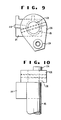
- Length 85 of holder 84 has a blade 114 press-fitted in a slot therethrough and extending therefrom into a wedge shaped opening 116 in the upper end of bar 86.
- a passage 118 extends from opening 116 through bar 86 and into a retainer plate 120 for a spring 122 that engages blade 114 and biases the LH knife toward its position 36h(Fig. 2).
- the cam follower 88 engages cam 90 (Fig. 3) and, against the bias of spring 122, rotates the LH knife to its position 36t.
- Follower 88 is carried by an internally threaded boss 124 on a lever 126 that is pinned to an upper, reduced end 128 of knife holder 84.
- follower 88 leaves cam 90 and spring 122 returns it to its position 36h.
- Func - tionally similar parts and elements impart rotational motions to RH knife 34.
Landscapes
- Life Sciences & Earth Sciences (AREA)
- Forests & Forestry (AREA)
- Engineering & Computer Science (AREA)
- Mechanical Engineering (AREA)
- Details Of Cutting Devices (AREA)
- Shaping By String And By Release Of Stress In Plastics And The Like (AREA)
- Extrusion Moulding Of Plastics Or The Like (AREA)
- Processing And Handling Of Plastics And Other Materials For Molding In General (AREA)
- Moulding By Coating Moulds (AREA)
- Replacement Of Web Rolls (AREA)
Applications Claiming Priority (2)
| Application Number | Priority Date | Filing Date | Title |
|---|---|---|---|
| US06/246,013 US4382396A (en) | 1981-03-20 | 1981-03-20 | Cast web diversion |
| US246013 | 1981-03-20 |
Publications (2)
| Publication Number | Publication Date |
|---|---|
| EP0061171A1 true EP0061171A1 (fr) | 1982-09-29 |
| EP0061171B1 EP0061171B1 (fr) | 1984-08-22 |
Family
ID=22928992
Family Applications (1)
| Application Number | Title | Priority Date | Filing Date |
|---|---|---|---|
| EP82102276A Expired EP0061171B1 (fr) | 1981-03-20 | 1982-03-19 | Dispositif pour couper et dévier une bande de matière fraîchement coulée |
Country Status (5)
| Country | Link |
|---|---|
| US (1) | US4382396A (fr) |
| EP (1) | EP0061171B1 (fr) |
| JP (1) | JPS6039539B2 (fr) |
| CA (1) | CA1171223A (fr) |
| DE (1) | DE3260599D1 (fr) |
Cited By (2)
| Publication number | Priority date | Publication date | Assignee | Title |
|---|---|---|---|---|
| FR2715605A1 (fr) * | 1993-12-01 | 1995-08-04 | Andelle Cartonneries | Dispositif de coupe et de réintroduction de carton simple-face pour onduleuse. |
| EP0678375A1 (fr) * | 1994-04-07 | 1995-10-25 | Karl Eugen Fischer GmbH Maschinenfabrik | Dispositif pour la coupe d'un matériau en bande contenant des éléments noyés dans la bande |
Families Citing this family (5)
| Publication number | Priority date | Publication date | Assignee | Title |
|---|---|---|---|---|
| US5159626A (en) * | 1990-07-10 | 1992-10-27 | Execudyne Ltd. | Multi-line telephone switching system |
| US6003421A (en) * | 1997-08-15 | 1999-12-21 | Milich; Bruce | Apparatus and method for cutting elongated webs of material |
| US20020134208A1 (en) * | 2001-03-23 | 2002-09-26 | Wilson John E. | Method and apparatus for trimming sheet metal |
| EP1438183B1 (fr) * | 2001-10-25 | 2007-01-24 | Pirelli Tyre S.p.A. | Procede et dispositif de decoupe d'un ruban de tissu recouvert de caoutchouc |
| IT1401265B1 (it) * | 2010-08-06 | 2013-07-18 | Gallucci | Dispositivo per lo scarico, da un piano di lavoro, di articoli piani nei quali sono ricavate, mediante taglio e/o incisione, porzioni su cui sono riprodotti disegni e/o scritte |
Citations (2)
| Publication number | Priority date | Publication date | Assignee | Title |
|---|---|---|---|---|
| US3557651A (en) * | 1968-12-23 | 1971-01-26 | United States Gypsum Co | Film-cutting apparatus |
| US3764085A (en) * | 1971-08-16 | 1973-10-09 | Du Pont | Method of and apparatus for handling material |
Family Cites Families (9)
| Publication number | Priority date | Publication date | Assignee | Title |
|---|---|---|---|---|
| US2665757A (en) * | 1949-01-07 | 1954-01-12 | Firestone Tire & Rubber Co | Automatic measuring and cutting ply feeder |
| US2837155A (en) * | 1955-04-28 | 1958-06-03 | American Viscose Corp | Sheet-sampling mechanism |
| US3276303A (en) * | 1965-01-18 | 1966-10-04 | Industrial Nucleonics Corp | Portable sample cutter |
| GB1156140A (en) * | 1967-02-15 | 1969-06-25 | Wiggins Teape Res Dev | Apparatus for Removing Samples from Lengthwise Moving Webs |
| FR2047661A5 (fr) * | 1969-05-13 | 1971-03-12 | Herbert Leonhard Maschin | |
| US3668922A (en) * | 1970-08-13 | 1972-06-13 | Industrial Nucleonics Corp | Web sampling method and apparatus |
| US3756527A (en) * | 1970-10-29 | 1973-09-04 | Du Pont | Method of and apparatus for threading a web of plastic film onto a windup roll and winding it thereon |
| US3762250A (en) * | 1971-06-16 | 1973-10-02 | Du Pont | Method of and apparatus for handling material |
| BE791742A (fr) * | 1971-11-26 | 1973-05-22 | Uniroyal Inc | Appareil de coupe a longueur pour matiere decoupee en biais pour nappesde ceinture d'enveloppe de bandage pneumatique de roue |
-
1981
- 1981-03-20 US US06/246,013 patent/US4382396A/en not_active Expired - Lifetime
-
1982
- 1982-03-18 CA CA000398738A patent/CA1171223A/fr not_active Expired
- 1982-03-19 EP EP82102276A patent/EP0061171B1/fr not_active Expired
- 1982-03-19 JP JP57043008A patent/JPS6039539B2/ja not_active Expired
- 1982-03-19 DE DE8282102276T patent/DE3260599D1/de not_active Expired
Patent Citations (2)
| Publication number | Priority date | Publication date | Assignee | Title |
|---|---|---|---|---|
| US3557651A (en) * | 1968-12-23 | 1971-01-26 | United States Gypsum Co | Film-cutting apparatus |
| US3764085A (en) * | 1971-08-16 | 1973-10-09 | Du Pont | Method of and apparatus for handling material |
Cited By (2)
| Publication number | Priority date | Publication date | Assignee | Title |
|---|---|---|---|---|
| FR2715605A1 (fr) * | 1993-12-01 | 1995-08-04 | Andelle Cartonneries | Dispositif de coupe et de réintroduction de carton simple-face pour onduleuse. |
| EP0678375A1 (fr) * | 1994-04-07 | 1995-10-25 | Karl Eugen Fischer GmbH Maschinenfabrik | Dispositif pour la coupe d'un matériau en bande contenant des éléments noyés dans la bande |
Also Published As
| Publication number | Publication date |
|---|---|
| JPS57165218A (en) | 1982-10-12 |
| JPS6039539B2 (ja) | 1985-09-06 |
| CA1171223A (fr) | 1984-07-24 |
| EP0061171B1 (fr) | 1984-08-22 |
| DE3260599D1 (en) | 1984-09-27 |
| US4382396A (en) | 1983-05-10 |
Similar Documents
| Publication | Publication Date | Title |
|---|---|---|
| US3319500A (en) | Apparatus for cutting an elongate web of material into strips | |
| US6286403B1 (en) | Cutting machine | |
| DE2229497C2 (de) | Verfahren zum Fördern von bahnförmigem Gut längs eines Verfahrensweges und Vorrichtung zur Durchführung des Verfahrens | |
| US5417382A (en) | Method and apparatus for winding a web | |
| US4699027A (en) | Cable stripping apparatus | |
| US4489900A (en) | Apparatus for automatically cutting and winding sheet material | |
| US4457195A (en) | Automatic strip cutting machine | |
| DE2154119A1 (de) | Verfahren und Vorrichtung zum Behandeln von Bahnenmaterial | |
| US4355794A (en) | Spreading machine cutter box assembly | |
| CN106584539A (zh) | 一种橡胶定长自动裁断机及裁断方法 | |
| US4382396A (en) | Cast web diversion | |
| WO1994029088A1 (fr) | Element coupe-bande | |
| US3503604A (en) | Cutting apparatus for cloth spreading machine | |
| CN218018732U (zh) | 一种基于消防用水带切割装置 | |
| CN112429563B (zh) | 一种塑料薄膜加工用切割装置 | |
| US3203291A (en) | Cutting machine | |
| DE2841386C2 (de) | Vorrichtung zum automatischen Querschneiden eines biegsamen Bahnmaterials | |
| KR102250813B1 (ko) | 롤 교환장치와 이를 이용한 롤 교환방법 | |
| CN111824840A (zh) | 一种塑料薄膜生产制造分切机及加工工艺 | |
| US3768349A (en) | Method and apparatus for severing elongated material into predetermined lengths | |
| DE102019006046A1 (de) | Vorrichtung und Verfahren zum intermittierenden Fördern einer Warenbahn längs einer Förderrichtung und zum Schneiden der Warenbahn | |
| US4995933A (en) | Method of producing mat strips from wide panels of adhesive material covered with release layers and apparatus for implementing the method | |
| CN220348466U (zh) | 高速分切机 | |
| CN223521945U (zh) | 胶带裁剪装置 | |
| CN224253976U (zh) | 一种不锈钢带冲裁设备 |
Legal Events
| Date | Code | Title | Description |
|---|---|---|---|
| PUAI | Public reference made under article 153(3) epc to a published international application that has entered the european phase |
Free format text: ORIGINAL CODE: 0009012 |
|
| 17P | Request for examination filed |
Effective date: 19820319 |
|
| AK | Designated contracting states |
Designated state(s): BE DE FR GB IT LU NL |
|
| ITF | It: translation for a ep patent filed | ||
| GRAA | (expected) grant |
Free format text: ORIGINAL CODE: 0009210 |
|
| AK | Designated contracting states |
Designated state(s): BE DE FR GB IT LU NL |
|
| REF | Corresponds to: |
Ref document number: 3260599 Country of ref document: DE Date of ref document: 19840927 |
|
| ET | Fr: translation filed | ||
| PLBE | No opposition filed within time limit |
Free format text: ORIGINAL CODE: 0009261 |
|
| STAA | Information on the status of an ep patent application or granted ep patent |
Free format text: STATUS: NO OPPOSITION FILED WITHIN TIME LIMIT |
|
| 26N | No opposition filed | ||
| ITTA | It: last paid annual fee | ||
| EPTA | Lu: last paid annual fee | ||
| PGFP | Annual fee paid to national office [announced via postgrant information from national office to epo] |
Ref country code: DE Payment date: 19981216 Year of fee payment: 18 |
|
| PGFP | Annual fee paid to national office [announced via postgrant information from national office to epo] |
Ref country code: NL Payment date: 19990105 Year of fee payment: 18 |
|
| PGFP | Annual fee paid to national office [announced via postgrant information from national office to epo] |
Ref country code: GB Payment date: 19990111 Year of fee payment: 18 |
|
| PGFP | Annual fee paid to national office [announced via postgrant information from national office to epo] |
Ref country code: LU Payment date: 19990113 Year of fee payment: 18 |
|
| PGFP | Annual fee paid to national office [announced via postgrant information from national office to epo] |
Ref country code: FR Payment date: 19990114 Year of fee payment: 18 |
|
| PGFP | Annual fee paid to national office [announced via postgrant information from national office to epo] |
Ref country code: BE Payment date: 19990312 Year of fee payment: 18 |
|
| PG25 | Lapsed in a contracting state [announced via postgrant information from national office to epo] |
Ref country code: LU Free format text: LAPSE BECAUSE OF EXPIRATION OF PROTECTION Effective date: 20000319 Ref country code: GB Free format text: LAPSE BECAUSE OF NON-PAYMENT OF DUE FEES Effective date: 20000319 |
|
| PG25 | Lapsed in a contracting state [announced via postgrant information from national office to epo] |
Ref country code: BE Free format text: LAPSE BECAUSE OF NON-PAYMENT OF DUE FEES Effective date: 20000331 |
|
| BERE | Be: lapsed |
Owner name: E.I. DU PONT DE NEMOURS AND CY Effective date: 20000331 |
|
| PG25 | Lapsed in a contracting state [announced via postgrant information from national office to epo] |
Ref country code: NL Free format text: LAPSE BECAUSE OF NON-PAYMENT OF DUE FEES Effective date: 20001001 |
|
| GBPC | Gb: european patent ceased through non-payment of renewal fee |
Effective date: 20000319 |
|
| PG25 | Lapsed in a contracting state [announced via postgrant information from national office to epo] |
Ref country code: FR Free format text: LAPSE BECAUSE OF NON-PAYMENT OF DUE FEES Effective date: 20001130 |
|
| NLV4 | Nl: lapsed or anulled due to non-payment of the annual fee |
Effective date: 20001001 |
|
| REG | Reference to a national code |
Ref country code: FR Ref legal event code: ST |
|
| PG25 | Lapsed in a contracting state [announced via postgrant information from national office to epo] |
Ref country code: DE Free format text: LAPSE BECAUSE OF NON-PAYMENT OF DUE FEES Effective date: 20010103 |