EP0061174B1 - Procédé et dispositif pour l'insertion d'un tube dans un tissu tubulaire avec formation de plis en Z - Google Patents
Procédé et dispositif pour l'insertion d'un tube dans un tissu tubulaire avec formation de plis en Z Download PDFInfo
- Publication number
- EP0061174B1 EP0061174B1 EP82102283A EP82102283A EP0061174B1 EP 0061174 B1 EP0061174 B1 EP 0061174B1 EP 82102283 A EP82102283 A EP 82102283A EP 82102283 A EP82102283 A EP 82102283A EP 0061174 B1 EP0061174 B1 EP 0061174B1
- Authority
- EP
- European Patent Office
- Prior art keywords
- ring
- tubular film
- weaving
- inflated
- weaving ring
- Prior art date
- Legal status (The legal status is an assumption and is not a legal conclusion. Google has not performed a legal analysis and makes no representation as to the accuracy of the status listed.)
- Expired
Links
- 239000004744 fabric Substances 0.000 title claims description 16
- 238000000034 method Methods 0.000 title claims description 10
- 230000015572 biosynthetic process Effects 0.000 title claims description 5
- 238000003780 insertion Methods 0.000 title 1
- 230000037431 insertion Effects 0.000 title 1
- 238000009941 weaving Methods 0.000 claims abstract description 39
- 239000000853 adhesive Substances 0.000 claims abstract description 15
- 230000001070 adhesive effect Effects 0.000 claims abstract description 15
- 239000011324 bead Substances 0.000 claims abstract description 10
- 239000002759 woven fabric Substances 0.000 claims 1
- 206010040954 Skin wrinkling Diseases 0.000 description 2
- 238000004519 manufacturing process Methods 0.000 description 2
- 239000000463 material Substances 0.000 description 2
- 230000002093 peripheral effect Effects 0.000 description 2
- 206010016352 Feeling of relaxation Diseases 0.000 description 1
- 239000004809 Teflon Substances 0.000 description 1
- 229920006362 Teflon® Polymers 0.000 description 1
- 238000005429 filling process Methods 0.000 description 1
- 239000011888 foil Substances 0.000 description 1
- 238000002347 injection Methods 0.000 description 1
- 239000007924 injection Substances 0.000 description 1
Images

Classifications
-
- D—TEXTILES; PAPER
- D03—WEAVING
- D03D—WOVEN FABRICS; METHODS OF WEAVING; LOOMS
- D03D37/00—Circular looms
-
- D—TEXTILES; PAPER
- D03—WEAVING
- D03J—AUXILIARY WEAVING APPARATUS; WEAVERS' TOOLS; SHUTTLES
- D03J1/00—Auxiliary apparatus combined with or associated with looms
-
- Y—GENERAL TAGGING OF NEW TECHNOLOGICAL DEVELOPMENTS; GENERAL TAGGING OF CROSS-SECTIONAL TECHNOLOGIES SPANNING OVER SEVERAL SECTIONS OF THE IPC; TECHNICAL SUBJECTS COVERED BY FORMER USPC CROSS-REFERENCE ART COLLECTIONS [XRACs] AND DIGESTS
- Y10—TECHNICAL SUBJECTS COVERED BY FORMER USPC
- Y10T—TECHNICAL SUBJECTS COVERED BY FORMER US CLASSIFICATION
- Y10T156/00—Adhesive bonding and miscellaneous chemical manufacture
- Y10T156/10—Methods of surface bonding and/or assembly therefor
- Y10T156/1002—Methods of surface bonding and/or assembly therefor with permanent bending or reshaping or surface deformation of self sustaining lamina
- Y10T156/1051—Methods of surface bonding and/or assembly therefor with permanent bending or reshaping or surface deformation of self sustaining lamina by folding
Definitions
- the invention relates to a method and a device for inserting a tubular web with the formation of Z-folds in a circular fabric hose during weaving and laying flat in a circular weaving machine.
- a folding device which places the flat-lying tubular web in Z-folds at certain intervals.
- the Z-folds are enclosed and fixed between the mutually facing strands of a double belt conveyor, which extends into the area of the pair of rollers laying flat and pulling off the round fabric hose, so that the Z-folds are fixed between the converging walls of the round fabric hose after leaving the double belt conveyor.
- the object of the invention is therefore to propose a method and a device which allow the outer fabric tube to be lined with a film tube with annular Z-folds which follow one another at intervals.
- this object is achieved in a method of the type mentioned at the outset in that the tube web squeezed between the pairs of flat-lay and feed roller is inflated into a bladder and the bladder is supported in an annular manner on and at a distance from the weaving ring in such a way that it is between the annular supports bulges, and that the annular bulge formed by the bulge, with its edge remote from the weaving ring, is inserted into the weaving ring with the formation of an annular circumferential Z-fold.
- a device for carrying out the method according to the invention is characterized in that above the weaving ring a pair of preferred rollers feeding the tubular web and between this and the weaving ring a cylindrical ring enclosing the inflated tubular web and concentric to the weaving ring, the outside diameter of which is smaller than the inside diameter of the weaving ring, are arranged, and that the ring is provided with drive and guide devices which move it in the axial direction between a position above the weaving ring and a position retracted into the weaving ring.
- the tubular web can be laid in Z-folds at a distance from the length of hose piece to be separated later from the round fabric hose for sack production, the tubular web possibly being attached to the round fabric hose above the Z-folds by adhesive applications.
- the cylindrical ring is inserted into the weaving ring when the tube bladder is stretched by pivoting the flaps in such a way that it forms an annular bead between the ring and the weaving ring.
- the tubular web adheres to the weaving ring in such a way that the bead is drawn in through the cylindrical ring which dips into the weaving ring, forming Z folds, and is then peeled off from the inner wall of the weaving ring until the Z folds of the desired length are formed.
- the tube sheet is provided with adhesive through the gaps in the ring, which are pressed against the inner wall of the circular fabric tube due to the overpressure of the air in the tube bladder.
- the tube bladder is then put into its slack state, so that the ring can be moved out of the weaving ring without pulling out the Z-fold formed again.
- the adhesive nozzles are expediently arranged on the carrier of the cylindrical ring and can also be moved in the longitudinal direction of the slots.
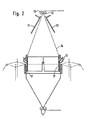
- a folding cylinder 6 is arranged above the weaving ring 1 and consists of a ring bracket 7 and a cylinder 8 attached to it made of relatively thin material.
- This cylinder 8 has four incisions 9. Its outer diameter is smaller than the inner diameter of the weaving ring 1, so that the cylinder 8 can be immersed more or less deeply in the weaving ring 1 by lowering the entire folding cylinder 6.
- an inlet ring 10 is firmly connected to the latter, which ring consists of a plurality of one Axis of teflon rolls lined up.
- this inlet ring 10 two plates 11 and 12 are pivoted toward and away from one another, between which the tubular film 14 transported by the preferred rollers 13 runs.
- 9 adhesive application nozzles 16 are provided in the area of the incisions, which can be moved up and down together with the folding cylinder and can also be moved relative to the folding cylinder.
- the tubular film 14 is inflated into a bubble between the preferred rollers 13 and the pair of draw rollers 5 with only slight pressure by injection with a needle or the like. While the circular tube 4 is now being woven, the tubular film 14 is simultaneously drawn in as an inner tube. The preferred rollers 13 and the pair of rollers 5 are driven at the same peripheral speed. If the swivel plates 11 and 12 are now moved towards each other, the hose bladder is compressed at this point. The displaced air causes the film 14 to press outwards between the folding cylinder 6 and the weaving ring 1 and form a bead 15. Depending on the width of the incisions 9, the film 14 can also be pressed out here. If the bead 15 is formed, the folding cylinder moves downwards at a higher speed than the take-off speed determined by take-off rollers 5 and dips into the weaving ring 1 until a Z-fold 17 of the desired depth has formed.
- the preferred rollers 13 are driven at an increased speed which is adapted to the speed of the folding cylinder 6.
- both the lowering speed of the folding cylinder 6 and the speed of the preferred rollers 13 are adapted to the speed of the pair of rollers 5, which is always driven at a constant peripheral speed.
- adhesive emerges from the nozzles 16, which are connected to the ring console 7, for example, via hydraulic piston-cylinder units (not shown). By acting on these piston-cylinder units, the nozzles 16 are moved upwards, that is to say in the direction of the console 7, as a result of which four adhesive strips are applied to the tubular film 14 evenly distributed over the circumference.
- Sacks are then formed from the round fabric web with the inner tube inserted, for example 50 kg sacks, in which the inner sack is connected to the outer sack by four adhesive strips in the area of the upper opening edge, so that the inner sack opens when it is opened for filling is brought up in any case.
- the Z-fold inserted immediately below the adhesive strips is gradually pulled open by the inflowing material, so that the inner sack can lie on the outer sack without tension and thus has no supporting function.
Landscapes
- Engineering & Computer Science (AREA)
- Textile Engineering (AREA)
- Making Paper Articles (AREA)
- Folding Of Thin Sheet-Like Materials, Special Discharging Devices, And Others (AREA)
- Shaping Of Tube Ends By Bending Or Straightening (AREA)
- Treatment Of Fiber Materials (AREA)
- Prostheses (AREA)
- Woven Fabrics (AREA)
- Looms (AREA)
- Rigid Pipes And Flexible Pipes (AREA)
Claims (7)
Priority Applications (1)
| Application Number | Priority Date | Filing Date | Title |
|---|---|---|---|
| AT82102283T ATE11308T1 (de) | 1981-03-25 | 1982-03-19 | Verfahren und vorrichtung zum einlegen einer schlauchbahn unter ausbildung von z-falten in einen rundgewebeschlauch. |
Applications Claiming Priority (2)
| Application Number | Priority Date | Filing Date | Title |
|---|---|---|---|
| DE3111829 | 1981-03-25 | ||
| DE3111829 | 1981-03-25 |
Publications (2)
| Publication Number | Publication Date |
|---|---|
| EP0061174A1 EP0061174A1 (fr) | 1982-09-29 |
| EP0061174B1 true EP0061174B1 (fr) | 1985-01-16 |
Family
ID=6128286
Family Applications (1)
| Application Number | Title | Priority Date | Filing Date |
|---|---|---|---|
| EP82102283A Expired EP0061174B1 (fr) | 1981-03-25 | 1982-03-19 | Procédé et dispositif pour l'insertion d'un tube dans un tissu tubulaire avec formation de plis en Z |
Country Status (7)
| Country | Link |
|---|---|
| US (1) | US4462431A (fr) |
| EP (1) | EP0061174B1 (fr) |
| JP (1) | JPS57171740A (fr) |
| AT (1) | ATE11308T1 (fr) |
| BR (1) | BR8201666A (fr) |
| DE (1) | DE3261897D1 (fr) |
| SU (1) | SU1077576A3 (fr) |
Families Citing this family (7)
| Publication number | Priority date | Publication date | Assignee | Title |
|---|---|---|---|---|
| WO1989012712A1 (fr) * | 1988-06-17 | 1989-12-28 | Ashimori Kogyo Kabushiki Kaisha | Procede et dispositif de production continue de tissus en biais |
| ATE166230T1 (de) * | 1990-08-31 | 1998-06-15 | Boehringer Ingelheim Pharma | Verwendung von anti-icam antikörpern zur herstellung eines präparats für die behandlung von endotoxinschock |
| FR2740146B1 (fr) * | 1995-10-18 | 1998-01-16 | Caer Yves | Machine de fabrication en continu de tubes textiles doubles |
| US7094936B1 (en) | 2001-07-20 | 2006-08-22 | Great Lakes Chemical Corporation | Process for preparing halogenated alkanes |
| CN104528449A (zh) * | 2014-12-30 | 2015-04-22 | 南京市高举高投资有限公司 | 一种包装袋自动折叠机及折叠包装袋 |
| CN113291916B (zh) * | 2021-06-04 | 2023-04-07 | 东莞市德合智能设备有限公司 | 一种高效快速胶袋叠卷设备 |
| CN113428721B (zh) * | 2021-06-18 | 2024-04-12 | 杭州欣浩医疗科技有限公司 | 一种内套折叠装置 |
Family Cites Families (8)
| Publication number | Priority date | Publication date | Assignee | Title |
|---|---|---|---|---|
| DE632547C (de) * | 1934-11-07 | 1936-07-09 | Guido Horn Maschinenfabrik | Gewebter Ring sowie Verfahren und Vorrichtung zu seiner Herstellung |
| DE869627C (de) * | 1951-08-18 | 1953-03-05 | Ver Seidenwebereien A G | Vorrichtung zum verzerrungsfreien Abziehen eines fortlaufend anfallenden, ueber einen Zylinder gezogenen Webstoffschlauches auf einen senkrecht zur Zylinderachse liegenden Wickelbaum |
| US2913799A (en) * | 1953-12-30 | 1959-11-24 | Sagem | Woven, lined tubular fabric and method and means for manufacturing same |
| GB1281234A (en) * | 1969-07-23 | 1972-07-12 | Reinhard Schulte G M B H | Improvements in or relating to the treatment of textile webs |
| US4065339A (en) * | 1972-01-18 | 1977-12-27 | Bayer Aktiengesellschaft | Process for producing fibre reinforced plastic tubes with flanges |
| IT1101349B (it) * | 1978-12-22 | 1985-09-28 | Mcplefan Spa | Telaio circolare cun dilatatore galleggiante per manufatti tubolari |
| DE2939970C2 (de) * | 1979-10-02 | 1982-07-01 | Windmöller & Hölscher, 4540 Lengerich | Vorrichtung zum Legen einer Folienbahn in Z-Falten |
| US4373979A (en) * | 1980-09-26 | 1983-02-15 | Workman Bag Company Ltd. | Sealed bags of plastic materials |
-
1982
- 1982-03-19 AT AT82102283T patent/ATE11308T1/de not_active IP Right Cessation
- 1982-03-19 DE DE8282102283T patent/DE3261897D1/de not_active Expired
- 1982-03-19 EP EP82102283A patent/EP0061174B1/fr not_active Expired
- 1982-03-24 JP JP57048070A patent/JPS57171740A/ja active Pending
- 1982-03-24 SU SU823410779A patent/SU1077576A3/ru active
- 1982-03-24 US US06/361,339 patent/US4462431A/en not_active Expired - Fee Related
- 1982-03-24 BR BR8201666A patent/BR8201666A/pt unknown
Also Published As
| Publication number | Publication date |
|---|---|
| EP0061174A1 (fr) | 1982-09-29 |
| JPS57171740A (en) | 1982-10-22 |
| ATE11308T1 (de) | 1985-02-15 |
| US4462431A (en) | 1984-07-31 |
| DE3261897D1 (en) | 1985-02-28 |
| SU1077576A3 (ru) | 1984-02-29 |
| BR8201666A (pt) | 1983-02-16 |
Similar Documents
| Publication | Publication Date | Title |
|---|---|---|
| DE2854586A1 (de) | Verfahren und vorrichtung zur herstellung von kunststoffhuelsen | |
| DE1296790B (de) | Vorrichtung zum Herstellen von formfesten Rohren | |
| EP0061174B1 (fr) | Procédé et dispositif pour l'insertion d'un tube dans un tissu tubulaire avec formation de plis en Z | |
| DE2504295A1 (de) | Vorrichtung zur herstellung von wegwerfwindeln | |
| DE6916834U (de) | Vorrichtung zur herstellung von verpackungen, vorzugsweise flachbodenpackungen, aus einem fortlaufenden folienstreifen. | |
| DE3436616C2 (fr) | ||
| DE1486975B1 (de) | Verfahren und Vorrichtung zur Herstellung von mehrschichtigen Beuteln oder Saecken | |
| EP0673750B1 (fr) | Dispositif pour la mise à plat d'un film tubulaire soufflé en matière thermoplastique | |
| DE1179089B (de) | Maschine zum Herstellen von Schlauch-abschnitten mit Seitenfalten fuer Faltbeutel | |
| DE2648235C2 (de) | Vorrichtung zum automatischen Herstellen mehrmals gefalteter, vernähter Sackböden | |
| DE2925553C2 (de) | Vorrichtung zum Einlegen einer Schlauchbahn in einem Rundgewebeschlauch | |
| DE1486975C (de) | Verfahren und Vorrichtung zur Her stellung von mehrschichtigen Beuteln oder Sacken | |
| DE2510515C3 (de) | Vorrichtung zum Einlegen einer Tieffalte in einen Blasfolienschlauch | |
| DE1436857C (de) | Verfahren und Schlauchmaschine zum Her stellen von Kunststoff Seitenfaltenventil sacken | |
| DE2752672B2 (de) | Vorrichtung zum Formen einer Verbindungsmuffe mit einer Ringnut | |
| DE2437840C2 (de) | Verfahren und Einrichtung zum Formen eines Schlauches | |
| DE1604609B2 (de) | Vorrichtung zum herstellen von beuteln oder saecken aus thermoplastischen kunststoffolien | |
| DE2231144C3 (de) | Verfahren und Vorrichtung zum Raffen von Hüllen | |
| DE1511014B2 (de) | Vorrichtung zum Herstellen eines geschlossenen Schlauches aus steifem Bandmaterial zum Herstellen gefüllter Packungen, vorzugsweise Tetraederpackung | |
| DE2329806C3 (de) | Verfahren und Vorrichtung zum Wenden eines flexiblen Schlauches mit seiner Innenseite nach außen | |
| DE1046997B (de) | Vorrichtung zum Herstellen eines Seitenfalten-Flachschlauches | |
| DE1504404C (de) | Vorrichtung zum Abquetschen eines Schlauches aus thermoplastischem Kunst stoff mit einem Quetschwalzenpaar | |
| DE2229700C3 (de) | Vorrichtung zum kontinuierlichen Herstellen eines Kunststoffrohres | |
| DE1779428C (de) | Vorrichtung zum Flachlegen einer aus einer ortsfesten Ringschlitzdüse ausgeformten Schlauchfolie aus Kunststoff | |
| DE1917411A1 (de) | Verpackungshuelse und Vorrichtung zur Verpackung unter Verwendung dieser Verpackungshuelse |
Legal Events
| Date | Code | Title | Description |
|---|---|---|---|
| PUAI | Public reference made under article 153(3) epc to a published international application that has entered the european phase |
Free format text: ORIGINAL CODE: 0009012 |
|
| AK | Designated contracting states |
Designated state(s): AT CH DE FR GB IT |
|
| 17P | Request for examination filed |
Effective date: 19830128 |
|
| ITF | It: translation for a ep patent filed | ||
| GRAA | (expected) grant |
Free format text: ORIGINAL CODE: 0009210 |
|
| AK | Designated contracting states |
Designated state(s): AT CH DE FR GB IT LI |
|
| REF | Corresponds to: |
Ref document number: 11308 Country of ref document: AT Date of ref document: 19850215 Kind code of ref document: T |
|
| REF | Corresponds to: |
Ref document number: 3261897 Country of ref document: DE Date of ref document: 19850228 |
|
| ET | Fr: translation filed | ||
| PLBE | No opposition filed within time limit |
Free format text: ORIGINAL CODE: 0009261 |
|
| STAA | Information on the status of an ep patent application or granted ep patent |
Free format text: STATUS: NO OPPOSITION FILED WITHIN TIME LIMIT |
|
| 26N | No opposition filed | ||
| PG25 | Lapsed in a contracting state [announced via postgrant information from national office to epo] |
Ref country code: GB Effective date: 19890319 |
|
| PG25 | Lapsed in a contracting state [announced via postgrant information from national office to epo] |
Ref country code: LI Effective date: 19890331 Ref country code: CH Effective date: 19890331 |
|
| GBPC | Gb: european patent ceased through non-payment of renewal fee | ||
| REG | Reference to a national code |
Ref country code: CH Ref legal event code: PL |
|
| PGFP | Annual fee paid to national office [announced via postgrant information from national office to epo] |
Ref country code: FR Payment date: 19900228 Year of fee payment: 9 |
|
| PGFP | Annual fee paid to national office [announced via postgrant information from national office to epo] |
Ref country code: AT Payment date: 19900306 Year of fee payment: 9 |
|
| PG25 | Lapsed in a contracting state [announced via postgrant information from national office to epo] |
Ref country code: AT Effective date: 19910319 |
|
| PG25 | Lapsed in a contracting state [announced via postgrant information from national office to epo] |
Ref country code: FR Effective date: 19911129 |
|
| REG | Reference to a national code |
Ref country code: FR Ref legal event code: ST |
|
| PGFP | Annual fee paid to national office [announced via postgrant information from national office to epo] |
Ref country code: DE Payment date: 19920407 Year of fee payment: 11 |
|
| PG25 | Lapsed in a contracting state [announced via postgrant information from national office to epo] |
Ref country code: DE Effective date: 19931201 |