EP0061204A1 - Ladeeinrichtung für Maschinengewehre - Google Patents
Ladeeinrichtung für Maschinengewehre Download PDFInfo
- Publication number
- EP0061204A1 EP0061204A1 EP82103634A EP82103634A EP0061204A1 EP 0061204 A1 EP0061204 A1 EP 0061204A1 EP 82103634 A EP82103634 A EP 82103634A EP 82103634 A EP82103634 A EP 82103634A EP 0061204 A1 EP0061204 A1 EP 0061204A1
- Authority
- EP
- European Patent Office
- Prior art keywords
- round
- ammunition
- housing
- augers
- firing chamber
- Prior art date
- Legal status (The legal status is an assumption and is not a legal conclusion. Google has not performed a legal analysis and makes no representation as to the accuracy of the status listed.)
- Granted
Links
Images


Classifications
-
- F—MECHANICAL ENGINEERING; LIGHTING; HEATING; WEAPONS; BLASTING
- F41—WEAPONS
- F41A—FUNCTIONAL FEATURES OR DETAILS COMMON TO BOTH SMALLARMS AND ORDNANCE, e.g. CANNONS; MOUNTINGS FOR SMALLARMS OR ORDNANCE
- F41A9/00—Feeding or loading of ammunition; Magazines; Guiding means for the extracting of cartridges
- F41A9/38—Loading arrangements, i.e. for bringing the ammunition into the firing position
- F41A9/45—Loading arrangements, i.e. for bringing the ammunition into the firing position the cartridge chamber or the barrel as a whole being tiltable or transversely slidable between a loading and a firing position
-
- F—MECHANICAL ENGINEERING; LIGHTING; HEATING; WEAPONS; BLASTING
- F41—WEAPONS
- F41A—FUNCTIONAL FEATURES OR DETAILS COMMON TO BOTH SMALLARMS AND ORDNANCE, e.g. CANNONS; MOUNTINGS FOR SMALLARMS OR ORDNANCE
- F41A15/00—Cartridge extractors, i.e. devices for pulling cartridges or cartridge cases at least partially out of the cartridge chamber; Cartridge ejectors, i.e. devices for throwing the extracted cartridges or cartridge cases free of the gun
-
- F—MECHANICAL ENGINEERING; LIGHTING; HEATING; WEAPONS; BLASTING
- F41—WEAPONS
- F41A—FUNCTIONAL FEATURES OR DETAILS COMMON TO BOTH SMALLARMS AND ORDNANCE, e.g. CANNONS; MOUNTINGS FOR SMALLARMS OR ORDNANCE
- F41A9/00—Feeding or loading of ammunition; Magazines; Guiding means for the extracting of cartridges
- F41A9/35—Feeding multibarrel guns
-
- F—MECHANICAL ENGINEERING; LIGHTING; HEATING; WEAPONS; BLASTING
- F41—WEAPONS
- F41A—FUNCTIONAL FEATURES OR DETAILS COMMON TO BOTH SMALLARMS AND ORDNANCE, e.g. CANNONS; MOUNTINGS FOR SMALLARMS OR ORDNANCE
- F41A9/00—Feeding or loading of ammunition; Magazines; Guiding means for the extracting of cartridges
- F41A9/38—Loading arrangements, i.e. for bringing the ammunition into the firing position
- F41A9/39—Ramming arrangements
- F41A9/42—Rammers separate from breech-block
Definitions
- This invention relates to an externally powered machine gun and to a feed system therefor; more particularly the invention relates. to such a gun having a housing, a motor means mounted on to the housing for powering the gun, gearing means mounted on to the housing and operably connected to the motor means, at least one barrel mounted on to the housing, at least one movable firing chamber movable between a first position aligned with the barrel and another position, and feed means operably connected to the gearing means for supplying ammunition to the firing chamber when in the second position.
- U.S. Patent 3,667,147 issued to Goldin et al on June 6, 1972 discloses a self-powered gun which has a breech block which vertically moves between a position aligned with the magazine and an upward position wherein it is aligned with the barrel and forms the firing chamber.
- the breech block has a follower cam engaging a slot within a cam plate which reciprocally moves such that the breech block has two dwell positions in alignment with the aforementioned magazine and barrel. Cartridges from the magazine are rammed in a rearward direction into the breech block which is then vertically moved to the upward position aligned with the firing chamber.
- a spring in the magazine urges each of the cartridges into the position aligned with the breech block so that they may be rammed into the breech block.
- a feed system needs to be provided which will ensure accurate alignment of cartridges prior to insertion into the firing chamber.
- the present invention provides a machine gun of the above-defined type, characterised in that the feed means includes a pair of augers rotatably mounted about parallel axes, each auger having a helical groove therein with the end of both grooves forming aligned zero pitched grooved rings on the augers, the augers being operably connected to the gearing means for continuous and simultaneous rotation such that portions of the helical grooves are longitudinally aligned to receive a round of ammunition, the grooved ring portions of the grooves being longitudinally aligned with each other for receiving a round of ammunition and maintaining the round in a dwell position therein as said augers rotate, the dwell position being formed by the zero pitched grooved rings, and further comprising ramming means for sliding the round of ammunition in the dwell position in the grooved rings axially forward into the aligned firing chamber.
- U.S. Patent 2,522,457 discloses an ammunition feed system which includes two augers each having a helical groove and being aligned to receive and feed transversely a round of ammunition within the grooves.
- each round of ammunition having reached the end of the groove, is forced by the augers against a surface of the housing which is shaped to receive the round and enable it to be fed to a required position. It is the continuous motion of the augers which provides this effect.
- the present invention includes augers having zero pitched portions of the grooves at one end thereof, which define a dwell position for each round of ammunition which can accordingly momentarily remain in that position despite continuous rotation of the augers prior to being rammed into the firing chamber. This leads to more reliable operation of the feed system.
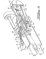
- a machine gun 10 has two vertically spaced barrels 12 and 14 mounted to a housing 16. A gap 18 is formed between the two barrels 12 and 14.
- the housing 16 houses a gearing system generally indicated at 20 which is operably driven by motor 22.
- the gearing system 20, as more clearly shown in Figure 2, is operably connected to a feed system generally indicated as 21.
- the feed system 21 includes a pair of augers 23 and 24 which are rotatably mounted about parallel axes which are transverse to the longitudinal axes of the barrels 12 and 14.
- Auger 23 has toothed gear 27 mounted thereon and auger 24 has toothed gear 29 coaxially mounted thereon.
- a pinion gear 31 is mounted between gears 27 and 29 and meshes therewith to cause both to rotate in the same direction.
- Gear 33 of gearing system 20 meshes with gear 27 to drive the augers 23 and 24.
- Each auger 23 and 24 has a helical groove 26 wrapped about its surface and axially ends with a zero pitch portion of the groove which forms a grooved ring 28 thereabout.
- Each auger 23 and 24 is positioned such that the upper portions of each helical groove 26 are longitudinally aligned to receive a round of ammunition thereon which enters from slot 30 in housing 16. Ammunition is delivered through slot 30 by conveyor belt (not shown) in a known manner.
- the housing 16 has a vertical wall 32 which slideably mounts an upper firing pin 34 and a lower firing pin 36 therein.
- the wall 32 has an aperture 38 therethrough which is aligned in front of the upper portions of aligned grooved rings 28.
- the wall 32 forms the rear portion of a vertically houses disposed compartment 40 which slideably a shuttle 42.
- the shuttle 42 is snugly received in compartment 40 such that the rear wall 32 abuts the rear end 44 of the shuttle 40 and a front wall 46 of compartment abuts the front end 48 of the shuttle 42.
- Side walls 50 and 52 of the compartment 40 have vertically extending grooves 54 therein which receive integral guide projections 56 extending from shuttle 42.
- Wall 50 also has a vertical extending slot 58 situated between the two grooves 54.
- Front wall 46 has an aperture 60 therethrough 61 leading to lower barrel 14 and as shown in Figure 4, an aperture 61 ads to upper barrel 12. Between apertures 60 and 61, wall 46 has a central aperture 62 therethrough in communication with central gap 18. Aperture 62 is coaxially aligned with aperture 38.
- the shuttle 42 has an upper bore 64 and a lower bore 66, which are parallel and vertically spaced apart extending from the rear end 44 to front end 48 of shuttle 42.
- the barrels 12 and 14, apertures 38 and 62, and bores 64 and 66 are spaced such that when the shuttle is in its lower position, as shown in Figures 2 and 4, the lower bore 66 is in communication with barrel 14 through aperture 60 and in communication with firing pin 36, and the upper bore 64 is aligned with apertures' 38 and 62.
- the bore 66 is in alignment with apertures 38 and 62, and the bore 64 is aligned with barrel 12 through aperture tg, and in communication with firing pin 34.
- the shuttle has an integral lug 63 passing through slot 58 for driving the shuttle up and down between its two positions.
- the integral lug 63 is driven by a drive system which includes a circumferential groove 65 on drum 67 which is rotatably mounted about a vertical axis. Coaxially mounted to the drum 67 is a toothed gear 72 mounted onto pin 74.
- the toothed gear 72 meshes with a toothed gear 70 which is attached to a shaft 68 which is driven by the gearing system 20.
- An endless conveyor belt 76 is mounted to housing 16 in front of aperture 62.
- the belt 76 is mounted about drive pulleys 78 which are operably linked in conventional fashion (not shown) to gearing system 20.
- the belt 76 is made from a suitable plastic material having a curved outer surface 80 with notches 82 spaced thereabout to aid in achieving the proper flexibility of the belt.
- the belt 76 is driven in a clockwise direction as shown in Figure 2 such that its side 84 is driven forwardly away from aperture 62.
- a series of roller bearings 86 is spaced apart from surface 84 such that a round of ammunition may extend between roller bearings 86 and belt surface 80 of side 84.
- a cam deflector 88 extends forwardly from belt 76 and bends to a side direction.
- Each firing pin 34 and 36 is driven by a cam which is coaxially mounted onto drum 67.
- cam 90 has an outer surface 92 which spirals outwardly with shoulder section 94 radially connecting the inner spiral end with the outer spiral end.
- the cam 90 as shown rotates in a counter clockwise direction and abuts a tappet 96 which is resiliently biased by spring 98 compressed between a collar 100 rigidly secured on tappet 96 and a flange 102 of housing 16.
- the tappet 96 has a knuckle end.104 pivotably mounted to firing pin lever 106 which is pivotably connected to housing 16 at one end 107 and to firing pin 34 at its other end 109. Firing pin 34 slideably extends through aperture 108 in wall 32. As the cam 90 rotates, the tappet 96 is biased to abut the surface 92 which, when rotated will withdraw the firing pin from compartment 40 and when shoulder 94 passes, tappet 96 will spring bias the firing pin 34 into the compartment 40 to abut a round of ammunition placed therein.
- the ramming system 91 is driven by a toothed crank 112 which has a connecting rod 114 pivotably mounted about pivot pin 116 radially displaced from the center of rotation 118 of the crank 112.
- a toothed rack 120 is mounted on the side of housing 16.
- the connecting rod 114 has a pinion gear 124 at end 122.
- the gear 124 engages the teeth 126 on rack 120.
- Slidably mounted within slot 128 is a ram shaft 130 which also engages pinion gear 124 by means of its teeth 132.
- Ram shaft 130 has ram lug 134 which engages the rear end of round 136 of ammunition.
- a claw 138 is pivotably mounted about pin 140 and engages a groove 142 within the cartridge portion of round 136.
- a camming edge 129 engages the claw to disengage it from groove 142 when the shaft 130 completely pushes round 136 into one of the bores 64 or 66.
- gear 33 of the gearing system 20 drives the toothed gears 27, 29, and 31 to rotate the augers 23 and 24 as shown in Figure 2 in a clockwise direction.
- a conveyor system (not shown) delivers ammunition to slot 30 which the augers 23 and 24 can receive in their aligned grooves 26 one at a time.
- the augers 23 and 24, rotate and move the engaged ammunition round transversely across until the round is resting in the grooved rings 28.
- the augers 23 and 24 continuously move but the round of ammunition as shown in Figure 4 obtains a dwell position due to the zero pitch of the rings 28.
- a round of ammunition 136 is in its dwell position in rings 28, the continuously rotating crank wheel 112, as shown in Figure 3, starts to drive the ram shaft 130 forward which accelerates the round through aperture 38 and into bore 64 as shown in Figure 4.
- the shuttle is driven by continuously rotating drum 67 from its first dwell position upwardly in a linear fashion until bore 64 is then aligned with aperture 61.
- the drum 67 creates a second dwell position at which the bore 64 is aligned with the barrel 12 and with its back end 44 flush against the wall 32 and the firing pin 34 directly behind the round 136.
- the bore 64 and rear wall 32 form a firing chamber for the round 136.
- the cam 90 has shoulder 94 pass by tappet 96 so that the firing pin is spring biased against the round 136 through aperture 108 to set off the round 136.
- the cam 90 Upon firing of round 136, the cam 90 immediately starts to withdraw the firing pin 34 from the chamber 64.
- a second round is delivered onto the grooved ring position 28 to be rammed by the ram shaft 130 into bore 66 which is now aligned with aperture 38. Any spent cartridge within bore 66 is then ejected, in the same fashion as a spent cartridge in bore 64, out through aperture 62 and accelerated by acceleration belt 76.
- the shuttle then is driven by drum cam 67 back to its first dwell position wherein bore 66 is aligned with barrel 14 and firing pin 36 directly behind the new incoming round in bore 66.
- Bore 66 and wall 32 form a firing chamber for the second round.
- Bore 64 is realigned with aperture 38 and 62.
- the firing pin 36 is operated to set off the new incoming round in bore 66 and the spent cartridge in 64 is then ejected in .the same fashion by a third round being driven by ram shaft 130.
- the shuttle is linearly driven between two positions and forms firing chambers for two fixed barrels.
- the feed system feeds both bores in the shuttle.
- Two continuously moving augers and a continuously moving drum allows for a simpler and lighter design due to the elimination of stop-go notion which creates higher stress loads.
- the needed dwell positions are accommodated by the sinusoidal motion of the crank 112 and the zero pitch of the ring grooves in the augers and the shape of the groove in the drum.
- the acceleration belt insures that during start-up any spent cartridge is quickly and fully withdrawn from the bores in the shuttle so that any risk of jamming is kept to a minimum.
- a lightweight compact externally powered machine gun is designed with a minimum amount of motion and with capabilities of shooting over three thousand rounds per minute.
Landscapes
- Engineering & Computer Science (AREA)
- General Engineering & Computer Science (AREA)
- Portable Nailing Machines And Staplers (AREA)
Applications Claiming Priority (2)
| Application Number | Priority Date | Filing Date | Title |
|---|---|---|---|
| US47402 | 1979-06-11 | ||
| US06/047,402 US4309933A (en) | 1979-06-11 | 1979-06-11 | Externally powered gun loading and ejection system |
Related Parent Applications (1)
| Application Number | Title | Priority Date | Filing Date |
|---|---|---|---|
| EP80301956.1 Division | 1980-06-10 |
Publications (2)
| Publication Number | Publication Date |
|---|---|
| EP0061204A1 true EP0061204A1 (de) | 1982-09-29 |
| EP0061204B1 EP0061204B1 (de) | 1984-05-16 |
Family
ID=21948760
Family Applications (3)
| Application Number | Title | Priority Date | Filing Date |
|---|---|---|---|
| EP82103634A Expired EP0061204B1 (de) | 1979-06-11 | 1980-06-10 | Ladeeinrichtung für Maschinengewehre |
| EP82103633A Expired EP0061203B1 (de) | 1979-06-11 | 1980-06-10 | Patronenauswurfeinrichtung für Maschinengewehre |
| EP80301956A Expired EP0021717B1 (de) | 1979-06-11 | 1980-06-10 | Maschinengewehr und Zufuhrsystem dafür |
Family Applications After (2)
| Application Number | Title | Priority Date | Filing Date |
|---|---|---|---|
| EP82103633A Expired EP0061203B1 (de) | 1979-06-11 | 1980-06-10 | Patronenauswurfeinrichtung für Maschinengewehre |
| EP80301956A Expired EP0021717B1 (de) | 1979-06-11 | 1980-06-10 | Maschinengewehr und Zufuhrsystem dafür |
Country Status (3)
| Country | Link |
|---|---|
| US (1) | US4309933A (de) |
| EP (3) | EP0061204B1 (de) |
| DE (1) | DE3067930D1 (de) |
Cited By (1)
| Publication number | Priority date | Publication date | Assignee | Title |
|---|---|---|---|---|
| US4791851A (en) * | 1987-06-02 | 1988-12-20 | Ares, Inc. | Gun for firing telescoped ammunition |
Families Citing this family (6)
| Publication number | Priority date | Publication date | Assignee | Title |
|---|---|---|---|---|
| DE3069622D1 (en) * | 1980-04-11 | 1984-12-20 | Ford Aerospace & Communication | Reciprocating feed system and automatic machine gun incorporating same |
| DE3237728C2 (de) * | 1982-10-12 | 1985-02-07 | Mauser-Werke Oberndorf Gmbh, 7238 Oberndorf | Automatische Feuerwaffe mit Revolvertrommel |
| US4697496A (en) * | 1985-06-17 | 1987-10-06 | Hughes Helicopters, Inc. | Method and apparatus for handling beltless ammunition in a twin-barreled gun |
| DE3625533C1 (en) * | 1986-07-29 | 1992-04-09 | Rheinmetall Gmbh | Gun for armoured fighting vehicle - has case ejector using forward and opposing ejector members |
| US4872391A (en) * | 1987-06-02 | 1989-10-10 | Ares, Inc. | Gun for firing telescoped ammunition, plus searing means |
| US9091333B2 (en) * | 2011-01-05 | 2015-07-28 | General Dynamics—OTS, Inc. | Loading machine for feeding a receiver |
Citations (3)
| Publication number | Priority date | Publication date | Assignee | Title |
|---|---|---|---|---|
| US2522457A (en) * | 1946-05-23 | 1950-09-12 | Martin James | Cartridge feeding mechanism for automatic cannon |
| US3667147A (en) * | 1970-01-22 | 1972-06-06 | Us Army | Rising block rifle and feed mechanism therefor |
| DE1960023C1 (de) * | 1969-11-29 | 1977-04-14 | Diehl Fa | Automatische Waffe zum Abfeuern von Patronen |
Family Cites Families (15)
| Publication number | Priority date | Publication date | Assignee | Title |
|---|---|---|---|---|
| DE85016C (de) * | ||||
| US225461A (en) * | 1880-03-16 | Jest available cop | ||
| US282553A (en) * | 1883-08-07 | Machine-gun | ||
| GB577338A (en) | 1944-02-18 | 1946-05-14 | George William Patchett | Improvements in power driven guns or cannons |
| US2528945A (en) * | 1944-08-19 | 1950-11-07 | Theodore H Carpenter | Dispensing device |
| US2646722A (en) * | 1947-11-19 | 1953-07-28 | United Shoe Machinery Corp | Device for disposing of ejected cartridge cases |
| US2725791A (en) * | 1949-11-14 | 1955-12-06 | Glenn L Martin Co | Case ejector for guns |
| US2856819A (en) * | 1953-06-23 | 1958-10-21 | Donald L Meyers | Automatic rocket launcher |
| US2965006A (en) * | 1955-09-26 | 1960-12-20 | John F O'brien | Twin-barrel gun with a drum and a multistation rammer |
| US2977856A (en) * | 1956-11-09 | 1961-04-04 | David C Fletcher | Feeding mechanism for a salvo gun |
| US2973692A (en) * | 1957-02-08 | 1961-03-07 | Altschuler Samuel | Single-shuttle twin-barrel gun |
| US2977854A (en) * | 1957-05-29 | 1961-04-04 | Eugene S Wassel | Single-sprocket twin-barrel gun |
| US2998758A (en) * | 1957-06-19 | 1961-09-05 | Herve J Ouellette | Revolving cage gun with a plurality of barrels and removable chambers |
| US2950652A (en) * | 1957-12-20 | 1960-08-30 | John F O'brien | Chambering mechanism for an automatic revolver type gun |
| US3296930A (en) * | 1965-02-23 | 1967-01-10 | John G Rocha | Clutch-lock for externally powered firearm feeding mechanism |
-
1979
- 1979-06-11 US US06/047,402 patent/US4309933A/en not_active Expired - Lifetime
-
1980
- 1980-06-10 EP EP82103634A patent/EP0061204B1/de not_active Expired
- 1980-06-10 DE DE8080301956T patent/DE3067930D1/de not_active Expired
- 1980-06-10 EP EP82103633A patent/EP0061203B1/de not_active Expired
- 1980-06-10 EP EP80301956A patent/EP0021717B1/de not_active Expired
Patent Citations (3)
| Publication number | Priority date | Publication date | Assignee | Title |
|---|---|---|---|---|
| US2522457A (en) * | 1946-05-23 | 1950-09-12 | Martin James | Cartridge feeding mechanism for automatic cannon |
| DE1960023C1 (de) * | 1969-11-29 | 1977-04-14 | Diehl Fa | Automatische Waffe zum Abfeuern von Patronen |
| US3667147A (en) * | 1970-01-22 | 1972-06-06 | Us Army | Rising block rifle and feed mechanism therefor |
Cited By (1)
| Publication number | Priority date | Publication date | Assignee | Title |
|---|---|---|---|---|
| US4791851A (en) * | 1987-06-02 | 1988-12-20 | Ares, Inc. | Gun for firing telescoped ammunition |
Also Published As
| Publication number | Publication date |
|---|---|
| EP0061203A1 (de) | 1982-09-29 |
| EP0021717A1 (de) | 1981-01-07 |
| EP0061203B1 (de) | 1984-04-25 |
| DE3067930D1 (en) | 1984-06-28 |
| EP0061204B1 (de) | 1984-05-16 |
| US4309933A (en) | 1982-01-12 |
| EP0021717B1 (de) | 1984-05-23 |
Similar Documents
| Publication | Publication Date | Title |
|---|---|---|
| US4658700A (en) | Drum magazine | |
| US4481858A (en) | Single barrel externally powered gun | |
| US4869150A (en) | Device for forward oriented case ejection in an externally driven automatic cannon | |
| US4418607A (en) | Single barrel externally powdered gun | |
| EP0061204B1 (de) | Ladeeinrichtung für Maschinengewehre | |
| US3277787A (en) | Device on an automatic firearm for the selective firing of two kinds of ammunition from two separate belts | |
| US4976185A (en) | Ammunition feed | |
| US2453786A (en) | Feed mechanism for rapid-fire guns | |
| US4127055A (en) | Cartridge feed system for an automatic gun | |
| US5370036A (en) | Telescoped ammunition revolver gun | |
| US3046842A (en) | Revolver gun with means for cutting the links of belted ammunition | |
| DE3050016C2 (de) | Zweistufen-Granatenzufuhrgerät mit Granatenzufuhrpfadsteuerung | |
| EP1006332A1 (de) | Munitionszuführung für eine Kanone | |
| US3611869A (en) | Automatic firearm with a changeover cartridge feed device | |
| US4373422A (en) | Reciprocating feed system | |
| US3106865A (en) | Loading device for automatic firearms having a revolver drum | |
| GB2152646A (en) | Air weapons | |
| US4505181A (en) | Stepwise double-cartridge-alternate feeder for an automatic weapon having a straight breech operation | |
| US3763741A (en) | Cartridge feeding and loading device for light weapons | |
| US2892408A (en) | Pre-engraved projectiles and gun for firing same | |
| AU599394B2 (en) | Firearm | |
| JPS61143700A (ja) | 外力駆動火砲のための遅延点火の監視装置 | |
| US4280392A (en) | Cartridge feed apparatus for an automatic firing weapon | |
| US4548120A (en) | Externally powered separate loaded ammunition cannon | |
| EP0038384B1 (de) | Zuführsystem mit hin- und hergehendem Förderelement und damit ausgerüstetes Maschinengewehr |
Legal Events
| Date | Code | Title | Description |
|---|---|---|---|
| PUAI | Public reference made under article 153(3) epc to a published international application that has entered the european phase |
Free format text: ORIGINAL CODE: 0009012 |
|
| 17P | Request for examination filed |
Effective date: 19820428 |
|
| AC | Divisional application: reference to earlier application |
Ref document number: 21717 Country of ref document: EP |
|
| AK | Designated contracting states |
Designated state(s): BE CH DE GB NL SE |
|
| GRAA | (expected) grant |
Free format text: ORIGINAL CODE: 0009210 |
|
| AC | Divisional application: reference to earlier application |
Ref document number: 21717 Country of ref document: EP |
|
| AK | Designated contracting states |
Designated state(s): BE CH DE GB LI NL SE |
|
| PG25 | Lapsed in a contracting state [announced via postgrant information from national office to epo] |
Ref country code: NL Effective date: 19840516 Ref country code: BE Effective date: 19840516 |
|
| REF | Corresponds to: |
Ref document number: 3067907 Country of ref document: DE Date of ref document: 19840620 |
|
| PG25 | Lapsed in a contracting state [announced via postgrant information from national office to epo] |
Ref country code: LI Effective date: 19840630 Ref country code: CH Effective date: 19840630 |
|
| NLV1 | Nl: lapsed or annulled due to failure to fulfill the requirements of art. 29p and 29m of the patents act | ||
| REG | Reference to a national code |
Ref country code: CH Ref legal event code: PL |
|
| PLBE | No opposition filed within time limit |
Free format text: ORIGINAL CODE: 0009261 |
|
| STAA | Information on the status of an ep patent application or granted ep patent |
Free format text: STATUS: NO OPPOSITION FILED WITHIN TIME LIMIT |
|
| 26N | No opposition filed | ||
| PGFP | Annual fee paid to national office [announced via postgrant information from national office to epo] |
Ref country code: GB Payment date: 19910517 Year of fee payment: 12 |
|
| PGFP | Annual fee paid to national office [announced via postgrant information from national office to epo] |
Ref country code: SE Payment date: 19910605 Year of fee payment: 12 |
|
| PGFP | Annual fee paid to national office [announced via postgrant information from national office to epo] |
Ref country code: DE Payment date: 19910627 Year of fee payment: 12 |
|
| PG25 | Lapsed in a contracting state [announced via postgrant information from national office to epo] |
Ref country code: GB Effective date: 19920610 |
|
| PG25 | Lapsed in a contracting state [announced via postgrant information from national office to epo] |
Ref country code: SE Effective date: 19920611 |
|
| GBPC | Gb: european patent ceased through non-payment of renewal fee |
Effective date: 19920610 |
|
| PG25 | Lapsed in a contracting state [announced via postgrant information from national office to epo] |
Ref country code: DE Effective date: 19930302 |
|
| EUG | Se: european patent has lapsed |
Ref document number: 82103634.0 Effective date: 19930109 |