EP0061239A1 - Système pour le pompage des liquides souterrains - Google Patents
Système pour le pompage des liquides souterrains Download PDFInfo
- Publication number
- EP0061239A1 EP0061239A1 EP82300960A EP82300960A EP0061239A1 EP 0061239 A1 EP0061239 A1 EP 0061239A1 EP 82300960 A EP82300960 A EP 82300960A EP 82300960 A EP82300960 A EP 82300960A EP 0061239 A1 EP0061239 A1 EP 0061239A1
- Authority
- EP
- European Patent Office
- Prior art keywords
- pump
- flexible
- fluid
- drum
- coupled
- Prior art date
- Legal status (The legal status is an assumption and is not a legal conclusion. Google has not performed a legal analysis and makes no representation as to the accuracy of the status listed.)
- Pending
Links
- 239000012530 fluid Substances 0.000 title claims abstract description 63
- 238000005086 pumping Methods 0.000 title claims abstract description 10
- 238000000034 method Methods 0.000 claims abstract description 16
- 230000004044 response Effects 0.000 claims description 11
- 230000001131 transforming effect Effects 0.000 claims description 10
- 239000004020 conductor Substances 0.000 claims description 8
- 238000009434 installation Methods 0.000 claims description 8
- 230000001681 protective effect Effects 0.000 claims description 8
- 238000003860 storage Methods 0.000 claims description 4
- 238000007789 sealing Methods 0.000 claims description 2
- 239000000725 suspension Substances 0.000 claims description 2
- 230000007246 mechanism Effects 0.000 abstract description 9
- 238000012856 packing Methods 0.000 description 8
- 230000015572 biosynthetic process Effects 0.000 description 7
- 230000008878 coupling Effects 0.000 description 7
- 238000010168 coupling process Methods 0.000 description 7
- 238000005859 coupling reaction Methods 0.000 description 7
- 238000005755 formation reaction Methods 0.000 description 7
- 229910000831 Steel Inorganic materials 0.000 description 5
- 239000010959 steel Substances 0.000 description 5
- 230000006378 damage Effects 0.000 description 3
- 238000012423 maintenance Methods 0.000 description 3
- 238000004519 manufacturing process Methods 0.000 description 3
- XLYOFNOQVPJJNP-UHFFFAOYSA-N water Substances O XLYOFNOQVPJJNP-UHFFFAOYSA-N 0.000 description 3
- 239000000919 ceramic Substances 0.000 description 2
- 238000011109 contamination Methods 0.000 description 2
- 239000007788 liquid Substances 0.000 description 2
- 230000008569 process Effects 0.000 description 2
- 230000009467 reduction Effects 0.000 description 2
- 239000004568 cement Substances 0.000 description 1
- 230000008859 change Effects 0.000 description 1
- 239000000356 contaminant Substances 0.000 description 1
- 230000008602 contraction Effects 0.000 description 1
- 230000001066 destructive effect Effects 0.000 description 1
- 238000010586 diagram Methods 0.000 description 1
- 238000006073 displacement reaction Methods 0.000 description 1
- 238000005553 drilling Methods 0.000 description 1
- 238000010304 firing Methods 0.000 description 1
- 230000001939 inductive effect Effects 0.000 description 1
- 239000003129 oil well Substances 0.000 description 1
- 230000010355 oscillation Effects 0.000 description 1
- 239000012188 paraffin wax Substances 0.000 description 1
- 239000013618 particulate matter Substances 0.000 description 1
- 230000000737 periodic effect Effects 0.000 description 1
- 238000011084 recovery Methods 0.000 description 1
- 239000004576 sand Substances 0.000 description 1
- 238000004904 shortening Methods 0.000 description 1
- 238000009987 spinning Methods 0.000 description 1
- 239000000126 substance Substances 0.000 description 1
- 238000005303 weighing Methods 0.000 description 1
Images




Classifications
-
- E—FIXED CONSTRUCTIONS
- E21—EARTH OR ROCK DRILLING; MINING
- E21B—EARTH OR ROCK DRILLING; OBTAINING OIL, GAS, WATER, SOLUBLE OR MELTABLE MATERIALS OR A SLURRY OF MINERALS FROM WELLS
- E21B43/00—Methods or apparatus for obtaining oil, gas, water, soluble or meltable materials or a slurry of minerals from wells
-
- E—FIXED CONSTRUCTIONS
- E21—EARTH OR ROCK DRILLING; MINING
- E21B—EARTH OR ROCK DRILLING; OBTAINING OIL, GAS, WATER, SOLUBLE OR MELTABLE MATERIALS OR A SLURRY OF MINERALS FROM WELLS
- E21B19/00—Handling rods, casings, tubes or the like outside the borehole, e.g. in the derrick; Apparatus for feeding the rods or cables
- E21B19/22—Handling reeled pipe or rod units, e.g. flexible drilling pipes
-
- E—FIXED CONSTRUCTIONS
- E21—EARTH OR ROCK DRILLING; MINING
- E21B—EARTH OR ROCK DRILLING; OBTAINING OIL, GAS, WATER, SOLUBLE OR MELTABLE MATERIALS OR A SLURRY OF MINERALS FROM WELLS
- E21B43/00—Methods or apparatus for obtaining oil, gas, water, soluble or meltable materials or a slurry of minerals from wells
- E21B43/003—Vibrating earth formations
-
- F—MECHANICAL ENGINEERING; LIGHTING; HEATING; WEAPONS; BLASTING
- F04—POSITIVE - DISPLACEMENT MACHINES FOR LIQUIDS; PUMPS FOR LIQUIDS OR ELASTIC FLUIDS
- F04B—POSITIVE-DISPLACEMENT MACHINES FOR LIQUIDS; PUMPS
- F04B47/00—Pumps or pumping installations specially adapted for raising fluids from great depths, e.g. well pumps
- F04B47/06—Pumps or pumping installations specially adapted for raising fluids from great depths, e.g. well pumps having motor-pump units situated at great depth
Definitions
- This invention relates to submersible pumps and more particularly to pumps for pumping oil from the earth.
- Prior art oil wells typically comprise a hole drilled in the ground, usually to a depth of a few hundred to several thousand feet, into which a reciprocating plunger type pump is inserted and connected to an actuating mechanism on the surface by a long, rigid rod assembly.
- a tubular casing is installed in the hole and is cemented in place.
- the casing is then perforated at the depth of the formation from which the oil is to be pumped to allow oil from the formation to flow into the casing.
- Various additional procedures to maximize the flow rate of the oil from the formation, such as "fracing" may be performed in the casing before the pump mechanism is installed.
- a typical pump mechanism comprises a stationary pump barrel with a check valve assembly in the bottom of the barrel.
- the top of this barrel is attached to rigid well tubing that supports the barrel in the casing at the desired depth.
- a tedious and time-consuming procedure is required to attach the well tubing to the barrel and lower the assembly into the casing.
- the tubing is provided in 30 foot lengths that are usually assembled in pairs after they are delivered to the well site. Each 60 foot long section of tubing must be lifted into a vertical position over the top opening in the casing by a winch in a work-over rig.
- the first section of tubing is fastened to the barrel with a threaded coupling by spinning the section of tubing.
- tubing and barrel are lowered into the-casing until just the top of the first section of tubing is projecting above the top of the casing.
- a second 60 foot section of tubing is raised into position over the first section and is coupled to that section by a threaded coupling while the first section is held in place by a slip clutch assembly.
- Many hours are spent making up the well tubing and lowering it into the casing until the barrel is at the desired depth.
- the second major component of the pump is the plunger assembly which comprises a polished rod that has an-attached head portion of approximately the same diameter as the inside diameter of the pump barrel.
- a plunger ball check valve assembly is carried inside the head portion and packing about the periphery of the head portion prevents oil from flowing past it.
- a pump rod guide is positioned on the pump rod. The plunger is attached to a pump rod which extends up through the well tubing to the' surface of the earth where the pump actuating mechanism is located.
- Lengths of pump rod which usually are 20 feet long and are assembled at the well site into "tripple" of 60 foot lengths, must be assembled to the plunger in the same manner as the well tubing was assembled or made up to the barrel. Each length of rod is lifted into place and attached to the previous length with threaded couplings that are integral with the ends of the rods.
- the final polished rod is the only rod which projects above the surface of the earth.
- a stuffing box and tee assembly are attached to the top of the well tubing at the wellhead, and the pipe to carry the oil to storage tanks couples to the tee.
- the actuating mechanism known as the horse's head pump assembly
- the assembly comprises a tower with a pivot on which is mounted a rocker arm with the horse's head at one end and a counter weight on the other end to counterbalance the weight of the horse's head and the rod.
- the rocker arm is driven by a connecting rod coupled to a crank on a gear box; which is belt driven by an electric motor. The motor provides the force to overcome friction and lift the liquid pumped as the rocker arm is raised and lowered.
- the pump is commonly known as a sucker rod pump and delivers fluid on both the up and the down strokes.
- the diameter of the rod above the head portion is approximately .7 times the inside diameter of the pump barrel so that about half the oil flowing through the plunger check valve on the down stroke of the rod flows into the volume between the rod and pump barrel created above the packing on the head portion by the down stroke and the other half flows up toward the surface of the earth.
- oil is sucked into the barrel through the barrel check valve while the column of oil in the well tubing above the plunger packing is lifted up to the surface of the earth, including that stored in the volume between the rod and pump barrel.
- the net volumes pumped during the down and up strokes are approximately equal.
- the pump may reach a "pumped off" condition in which dissolved gasses in the oil may be released as it is sucked through the barrel check valve during the up stroke, and part of the volume of the barrel will be filled with gas instead of liquid.
- oil will not be forced into the plunger check valve during the first part of each down stroke and the column of oil above the packing will actually descend from the surface of the earth during that time. This will reduce the volumetric efficiency of the pump and can produce destructive "water-hammer” like impacts on every down stroke, thus shortening pump life.
- the pumped off condition was usually detected by an on site person known as a "pumper" putting his hand on the polished rod where he could feel the vibration caused by the plunger hitting the top surface of the oil in the barrel. He would then adjust a timer on the pump motor so that the pump would shut off at approximately the time during each pumping cycle when the pumped off condition was reached.
- a pum p er To keep a pump working at maximum efficiency requires constant attention by an experienced pum p er.
- There are other methods of determining how long a pump should be run each day for maximum efficiency but they usually involve even greater expense or complexity that the method just described.
- the basic sucker rod pump is simple and reliable, it none the less requires periodic maintenance due to the wearing of parts, clogging of perforations in the casing or the valves by sand, paraffin or other substances, etc.
- maintenance When maintenance is required the well must be shut down for several days while the pump is laboriously dis-assembled by reversing the make up process described above.
- This disassembly is costly not only because of the 4 to 5 man crew required to perform the work, but because the well is not producing during the several days required to disassemble, service and reassemble the pump.
- tubing and rods may be resonant or nearly resonant at the frequency of the pump's oscillation, and the relative extension and contraction of the rod and tubing may be on the order of the stroke length of the rocker. Careful selection of pump stroke or rocker stroke length and frequency must be made to avoid . undesirable conditions.
- Safety concerns involve both workers and strangers, such as children, who may wander into an oil field. Since many pumps are on timers a person may be near or in contact with a pump thinking it is not in operation when it may suddenly start u p without warning. Such occurrences have caused serious injuries in the past. In addition many workers' injuries have resulted from fatigue during the long and strenuous process of putting the pump in the casing or removing it for maintenance.
- the present invention provides a method of extracting fluid from the earth through a hole formed in the earth including the steps of lowering submersible pump means into the hole with a flexible support member, and applying power to the pump means through flexible power conducting means, characterized by the step of transporting fluid pumped by the pump means to the surface of the earth through flexible fluid transport means.
- a method as set forth in the last preceding paragraph may be further characterized by the step of providing a protective sheath encasing the flexible support member, the flexible power conducting means and the flexible fluid transport means.
- a method as set forth in either one of the last two preceding paragraphs is preferably characterized in that the step of lowering the pump means further comprises unreeling the flexible support member from a storage reel as the pump means is being lowered into the hole.
- the present invention further provides a system for pumping subterranean fluids out of a hole formed in the surface of the earth including submersible pump means for pumping a fluid in which the pump means is submersed, and flexible power conductor means coupled to the pump means for supplying power to the pump means, characterized by a flexible support member attached to the pump means and coupled to the flexible power conductor means, support means at the -surface of the earth attached to the flexible support member for supporting the pump means and the support member in the hole, and flexible fluid transport means coupled to the pump means and the support means for transporting pumped fluid from the pump means to the surface of the earth.
- the flexible support member may be a cable.
- a system as set forth in either one of the last two preceding paragraphs is preferably further characterized by signal conducting means coupled between the pump means and the support means.
- a system as set forth in any one of the last three immediately preceding paragraphs is preferably further characterized in that the support member, the power conductor and the fluid transport means are encased in a protective sheath.
- a system as set forth in any one of the last four immediately preceding paragraphs; including pressure means attached to the pump means for sensing the pressure of the fluid in the hole, is preferably characterized by control means coupled to the transducer means and the pump means for controlling the pump means by causing power to be supplied to the pump means in response to the transducer means sensing a first pressure and halting the supply of power to the pump means in response to the transducer means sensing a second pressure.
- a system as set forth in any one of the last five immediately preceding paragraphs is preferably characterized by motive means on the surface connected to the support member for inserting and retracting the pump means from the hole.
- a system as set forth in any one of the last six immediately preceding paragraphs, is preferably characterized in that the motive means includes reel means around which the support member is wound when the pump means-is retracted from the hole and from which the support member is unreeled when the pump means is inserted into the hole.
- a system as set forth in any one of the last seven immediately preceding paragraphs is preferably characterized in that the motive means includes reel means around which the support member, the power conducting means and the fluid transport means are wound together when the pump means is retracted from the hole and from which the support member, the power conducting means and the fluid transport means are unreeled together when the pump means is inserted into the hole.
- a system as set forth in any one of the last eight immediately preceding paragraphs is preferably characterized in that a removable junction box is connected to the support member, the power conducting means, the fluid transport means and the signal conducting means at the surface of the earth wherein the junction box is wound on the reel means when the pump means is retracted from the hole.
- the present invention further provides a pump including a pump body having a fluid inlet and a fluid outlet, rotating motive means mounted to the pump body having a power input and an output shaft for imparting rotational motion to the output shaft in response to the application of power to the input characterized by transforming means coupled to the output shaft for transforming rotational motion to linear motion, a stationary plunger mounted in the pump body, a movable pump barrel coupled to the transforming means and which is movable in a reciprocating manner over the plunger by the transforming means, first valve means coupled to the pump barrel for admitting fluid to the pump barrel, second valve means coupled to the plunger and to the fluid outlet for allowing fluid to flow out of the pump barrel, and switching means coupled to the motive means for changing the direction of rotation of the motive means and thus the direction of travel of the pump barrel.
- a pump as set forth in the last preceding paragraph is preferably further characterized in that the output shaft is threaded, and the transforming means comprises a ball nut on the threaded shaft and coupled to the pump barrel and spline means on the pump barrel which engages the pump body for permitting the pump barrel to reciprocate in the pump body.
- a pump as set forth in either one of the last two immediately preceding paragraphs is preferably further characterized in that the plunger has an outer diameter substantially equal to the bore of the pump barrel and is mounted on a hollow rod having an outer diameter which is less than the bore of the pump barrel, the second valve means can admit fluid from the pump barrel into the hollow rod, and the motive means is an electric motor.
- a pump as set forth in any one of the last three immediately preceding paragraphs is preferably further characterized by flexible seal means for sealing the motive means from the fluid.
- a pump as set forth in any one of the last four immediately preceding paragraphs is preferably further characterized by a flexible suspension member attached to the pump body for suspending the pump in the fluid to be pumped.
- a pump as set forth in any one of the last five immediately preceding paragraphs is preferably further characterized by flexible fluid transport means connected to the fluid outlet for transporting fluid from the pump, and flexible power conducting means connected to the motive means for supplying power to the motive means.
- a pump as set forth in any one of the last six immediately preceding paragraphs is preferably further characterized by a protective sheath around the support member, the fluid transport means and the powe conducting means.
- the present invention further provides a subterranean pump installation and removal apparatus for a pump suspended in a hole in the earth by a flexible line, the apparatus being characterized by engaging means for engaging the flexible line, drum means coupled to the engaging means, and motive means coupled to the drum means for causing the drum means to turn in a first direction to wind the flexible line about the drum means and for causing the drum means to turn in a second direction to unwind the flexible line from the drum means.
- Apparatus as set forth in the last preceding paragraph is preferably further characterized by guide means for guiding the flexible line from the hole to the drum means, oscillating means coupled to the drum means for causing the drum means to oscillate while the flexible line is being wound about the drum means to more evenly distribute the flexible line over the surface of the drum means, and a mobile support structure for supporting and transporting the engaging means the drum means, the motive means, the guide means and the oscillating means.
- Apparatus as set forth in the last preceding paragraph is preferably further characterized in that the guide means comprises support means mounted on the mobile support structure, pulley means for supporting and guiding the flexible line, and hinge means for supporting the pulley means on the guide means and having a hinge axis, the hinge axis being substantially coincident with the axis of the portion of the flexible line between the pulley means and the hole.
- Apparatus as set forth in any one of the last three immediately preceding paragraphs is preferably characterized in that the flexible line is terminated in a junction box comprising an outer casing having first and second curved sides, the radius of curvature of the first side being substantially equal to the radius of curvature of the pulley means and the radius of curvature of the econd side being substantially equal to the radius of curvature of the drum means, the drum means having a slot for receiving the junction box.
- drum means comprises an inner drum coupled to the motive means, a cable coupled to the inner drum and the engaging means, and an outer drum concentric with the inner drum and having the slot through which the cable passes.
- Apparatus as set forth in any one of the last five immediately preceding paragraphs is preferably further characterized in that the oscillating means comprises first angle sensing means for sensing the angular position of the pulley means with respect to the support means, second angle sensing means for sensing the angular position of the drum means with respect to the mobile support structure, and control means coupled to the first and second angle sensing means to control the angular position of the drum means with respect to the mobile support structure in response to the angular position of the pulley means with respect to the support means.
- control means comprises an hydraulic piston coupled to the drum means and the mobile support structure, differential amplifier means having inputs coupled to the first and second angle sensing means and having an output, servo valve means coupled to the output of the differential amplifier means and to the hydraulic piston for supplying hydraulic fluid to the hydraulic piston in response to the output of the differential amplifier means, and hydraulic fluid supply means for supplying hydraulic fluid to and receiving hydraulic fluid from the servo valve means.
- a submersible oil pump is attached to a flexible cable which suspends the pump in the well casing.
- Power is provided to a motor in the pump by a flexible power cable, and the oil from the pump is carried to the surface of the earth by a flexible hose.
- the support cable, power cable and hose are all encased in a protective sheath to make a single flexible line.
- the flexible line Before the pump is placed in the hole, the flexible line is wound on a reel, and the pump is lowered into the casing by unwinding the reel. When it is desired to remove the pump from the hole, the flexible line may again be wound on the reel.
- This reel may conveniently be mounted on the back of a lorry or truck so that it can be easily transported from one well site to another.
- the truck may also have a guiding mechanism to guide the flexible line from the wellhead to the reel and evenly distribute the flexible line on the reel.
- the guiding mechanism may comprise a pulley hingeably mounted on a boom attached to the truck, together with an oscillating drive for slowly pivoting the reel back and forth about a vertical axis on the truck. As the flexible line passes over the pulley and is wound on the reel, it is evenly distributed over the surface of the reel due to this back and forth motion of the reel.
- the pump may comprise a submersible, sealed motor driving a rotary to reciprocating motion transformer.
- the motion transformer may be connected to a moving pump barrel having an inlet valve and reciprocating on a fixed plunger which has an outlet valve.
- wires can also be included in the protective sheath of the flexible line.
- pumping efficiency can be maximized by using an automatic control system to control the pump in response to conditions in the well measured by transducers such as a pressure transducer.
- One of the great advantages of the present invention is the saving in labor and time in the installation and removal of a pump from a hole. Where in the past, placing a pump in the hole took several days, it need take only a matter of hours with the present invention. In addition a smaller crew is required. Safety should be increased significantly because all of the moving parts are below ground, out of the reach of curious strangers or careless workers. Since the installation and removal can be accomplished in less time than the prior art and requires less manual labor, there is less opportunity for injuries to workers.
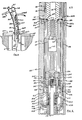
- FIGS 1 and 2 show a prior art oil pump such as that hereinbefore described.
- a hole 1 is drilled through various subterranean formations here denoted as an overburden 3 1 a water bearing zone 5.
- a casing 13 inserted in the hole is smaller than the inside diameter of the hole and leaves an annular space 15 which may be partially filled with drilling mud and debris.
- Cement 17 is driven into the annular space 15 by a bullnose 19 to seal off the various strata from one another and to prevent water, for example, from flowing into the oil producing zone.
- Perforations 21 in the casing and fractures 23 in the producing zone formation are formed to allow oil 25 to flow into the casing.
- a pump 27 with an inlet 29 is suspended in the casing by tubing 31 and is actuated through a rod 33.
- the casing and tubing are fastened to a wellhead 34 where a tee 37 has a pipe 39 to carry the oil to a storage tank (not shown).
- a polished rod 41 connected to the well rod 33 passes through a stuffing box 43 and is also connected to a horse's head 45 through a cable 47 and yoke 49.
- the horse's head is on a rocker arm 51 supported on a pivot 53 on a tower 55.
- the rocker arm is counterbalanced by a counter weight 57 and is driven by a crank 61 through a connecting rod 59.
- the crank is connected to a gear box 63 which is driven by a motor 65; and both the motor and the gear box sit on a frame 67.
- the pump has a barrel 69 ( Figure 2) connected to the tubing 31 by a coupling 71. At the top end of the barrel there is a pump rod guide 73; and, at the bottom, an entrance ball check valve 75 connected to the inlet 29.
- the well rod 33 is connected to a pump rod 77 on which is mounted a plunger 79 with packing 81 and a plunger ball check valve 83.
- the plunger is just slightly smaller than the bore 85 of the barrel,
- a pump 101 in accordance with the preferred embodiment of the invention is shown suspended in the hole 1 within the casing 13.
- the pump itself is shown in greater detail in Figure 4.
- a steel cable 103 is connected to the top of the pump by a lift eye 105 and to the wellhead 35 to support the pump 101 at the proper depth in the hole 1.
- the pump components are mounted in a body 107 having a top plate 108 which is attached to the lift eye 105.
- a submersible motor 109 coupled to a lead screw 111.
- a ball nut 113 on the lead screw 111 is coupled to a movable pump barrel 115 and has splines l19 at the lower end of the pump barrel. The splines engage grooves 117 in the body 107 to permit axial movement of the barrel in the body.
- the motor rotates the lead screw 111, the ball nut 113 will cause the pump barrel 115 to move away from or toward the motor depending upon the direction of rotation of the motor.
- a limit switch assembly 121 is provided to change the direction of rotation of the motor when the barrel reaches the limit of its travel in each direction.
- the pump barrel 115 slides over a stationary plunger 123 that is mounted on a pump rod 125.
- the pump rod is fastened in turn to the pump body top plate 108.
- packing 124 around the plunger as well as packing 126 at the top of the pump barrel.
- the diameter of the pump rod 125 is selected to be the inverse of the square root of two, times the inside diameter of the pump barrel 115, thus leaving an annular space 132 between the pump rod and barrel.
- the pump barrel moves upward, it forces oil in region 133 through a check valve 135 in the plunger 123 into a passageway 137 in the pump rod 125 and into the annular space 132.
- half of the oil will flow into the passageway 137 and the other half into the annular space 132.
- the oil that flows into the annular space 132 on the up stroke of the pump barrel will be forced into the passageway 137 on the down stroke by the packing 126.
- the passageway 137 is connected to an oil outlet 139 and thus half of the oil that enters the pump barrel will flow through the outlet on the up stroke of the pump and the other half on the down stroke; maintaining a continuous flow of oil through the outlet.
- a flexible hose 141 is coupled to the outlet 139 and is used to carry the oil up to the wellhead where it connects to the pipe 39 through a junction box 138.
- Power is supplied to the motor 109 through a power cable 143 which is also connected through the junction box 138 to a control box 145 on the surface of the earth. Wires in the power cable 143 are connected through connectors 144 to power leads 142 which carry the electrical power to the motor 109.
- the power leads are enclosed in a passageway 148 in the body 107.
- the steel cable 103, hose 141 and power cable 143 are all encased in a flexible, protective sheath 147 to form a single flexible line 149.
- a cover 146 is fastened to the top plate 108 to protect the lift eye 105, outlet 139 and connectors 144 and to provide convenient access to these components when the pump needs to be serviced.
- Four threaded rods 150 pass through the cover 146, top plate 108, body 107 and motor 109 to fasten the assembly together.
- seal 151 In order to prolong the life of the motor, it is sealed in clean oil 142 by an upper seal 151 and a lower seal 153.
- These seals are preferably convoluting diaphragms, sold under the name "Bellowframs" which. permit translational movement without requiring a sliding seal that might admit contaminants.
- the seal 151 is attached between the pump body 107 and the lower portion of the pump barrel 115 " and the seal moves with the reciprocation of the pump barrel.
- the lower seal 153 is mechanically biased by a spring 155 to maintain a slight positive pressure differential between the clean oil 152 and the oil in the casing.
- a pressure transducer 161 is mounted below the motor 109 for sensing the pressure of the oil in the hole at the pump. Signals from the pressure transducer can be carried to the surface of the earth by wires in the sheath 147, it desired, for recording or control purposes.
- the pressure transducer 161 can also be used for controlling the motor 109 as shown in Figure 5.
- the pressure transducer 161 comprises a helical coil Bourdon tube 171 mounted on an evacuated chamber 173.
- a rod 175 is fastened to the top of the Bourdon tube 171, and a moving electrical contact 177 is fastened to the rod.
- the power leads 142 are connected to a power relay 179 which in turn is connected to the motor 109 to switch the power to the motor on and off.
- One of the power leads is also connected to one end of the relay solenoid and the other end of the solenoid is connected to a stationary contact 181.
- the Bourdon tube will hold moving the contact 177 in contact with the station ary contact 181.
- the Bourdon tube will start to "unwind" and the moving contact will be rotated away from the stationary contact as when oil pressure rises above a predetermined limit.
- An example of this type of pressure transducer is described in greater detail in U.S. Patent Specification No. 3,279,258.
- the power leads 142 are connected to the normally open contacts of the power relay 179 so that when the moving contact 177 is not in contact with the stationary contact 181 and consequently no power is being applied to the solenoid of the power relay, power will be applied to the motor. When the contacts 177 and 181 close, power is removed from the motor. It should be noted that these contacts are in the clean oil 152 to prolong their operas ting life.
- the pressure of the oil in the hole is transmitted to the pressure transducer through the seal 153 which has a relatively insignificant bias exerted against it by the spring 155; resulting in a pressure differential between the clean oil 152 and the oil in the hole of 3 to 4 psi.
- a sound transducer 165 can also be mounted below the motor 109 for inducing sonic disturbances in the oil producing formation to increase the production of oil from the formation.
- the operation and use of such sonic transducers is described in detail in U.S. Patent Specifications Nos. 3,527,300 and 3 583,677.
- Power is supplied to the sound transducer through a wire 163 which also passes from the sheath 147 through another-passageway parallel to the passageway 148.
- FIG. 6 shows an enlarged cross-section of the coupling. between the motor 109 and the lead screw 111.
- the motor 109 has a splined output shaft 191 with a sun gear 193 of a planetary gear set 192 mounted on it with retaining rings 194.
- the sun gear 193 engages planet gears 195 which are mounted on a planetary carrier 197 on spindles 199.
- the planetary carrier 197 has a splined hole that mates with a splined end 201 of the lead screw 111, and these two parts are held'together by a screw 203 and washer 205.
- a castellated end cap 207 with a plurality of pins 209 is fastened to the planetary carrier 197 with bolts 211.
- a ball bearing 213 has an outer race 215 held in the body 107 by a retaining ring 217 and an inner race 219 held in the end cap 207 by a retaining ring 221.
- the ball bearing 213 acts both as a thrust bearing and a rotational bearing for the planetary gear set 192.
- Pins 209 engage an apertured plate 223 on a stack of washers 225, each, including the apertured plate, having a tab'227. With each rotation of apertured plate 223 the tab on one of the washers contacts the tab on the next lower washer and causes it to turn with the washers above it.
- a tab 228 on the bottom washer engages a reversing switch 229 for the motor 109, and when the bottom washer is turned by the washer above it, it causes the motor to reverse direction.
- the number of rotations between reversals is determined by the number of washers in the stack which is, in turn, determined by the length of the throw of the pump.
- each of the washers is separated by a bearing washer 231, and the washers are assembled about a sleeve 233.
- the motor l09 is a three phase four pole motor of the type commonly available from such suppliers-as Franklin.
- the reversing switch 229 is a double pole, double throw switch which reverses two of the three power leads to the motor when it is actuated by the bottom washer 225. Since the motor is relatively long and thin, it has relatively low rotational inertia and can be reversed comparatively quickly. For example, a motor operating at 1725 rpm can be reversed in about 60 milliseconds. With a gear reduction of 3.33:1 in the planetary gear set and a six inch pump throw as discussed above, the motor will operate for about 3 seconds in each direction, so that the time required to reverse the motor is only about 2% of the operating time.
- Figure 7 shows a cross-sectional view of one of the connectors 144.
- a conductor 235 in a ceramic body 237 has common spring connectors 239 slipped over each end. Wires are soldered to each connected 239, and rubber hoods 241 are fitted over the connectors 239 and ceramic body 237.
- Figure 6 also shows a cross section of the portion of the pump where the ball nut 113 on the lead screw 111 is threaded into the pump barrel 115, clamping a splined member 120 with splines 119 between the ball nut and the barrel.
- Oil flowing through the inlet 127 in the body 107 flows into an annular groove 243 and from there past the upper seal 151 through grooves 118, which may be a contin uation of the grooves 117, and into the inlet 129.
- These grooves in cooperation with the upper seal act as a filter to keep undesirably large particulate matter from entering the pump.
- One end 245 of the upper seal 151 is clamped between two cylindrical portions of the body 107 and another end 247 of the upper seal 151 is clamped between the pump barrel 115 and a clamp ring 249.
- the clamp ring 249 is held in place by a retaining ring 251 that fits in a tapered groove 253 in the pump barrel.
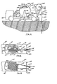
- Figure 8 shows a partially cut away perspective view of the wellhead 35 supporting the junction box 138.
- a support plate 255 is bolted to the wellhead 35 with bolts 257.
- the support plate has a slot 259 in it to permit it to be slid off the wellhead while the flexible line 249 is in the hole.
- Welded on two sides of the junction box 138 are a pair of support bars 261 that sit in a milled groove 263 in the support plate 255 to support the junction box when it is in place.
- a master cable 265 carried the power cable 143 and wires 163 from the junction box-138 to the control panel 145.
- the various conductors in the master cable 265 are joined to the respective conductors from the flexible line 149 by connectors 267.
- the steel cable 103 is formed into a loop 268 which is supported by a pin 269 in the junction box.
- the flexible hose 141 is connected to a junction coupling 271 to which is also connected a hose 273 that carries the oil to the pipe 39.
- the various items in the interior of the junction box 138 are accessible by removing a cover plate 274 on one side of the junction box.
- a lift eye 275 is provided at the top of the junction box 138 to facilitate lifting the junction box, flexible line and pump out of the hole 1.
- the slot 259 provides access to the well for testing and inspectiqn purposes, and an access cover 277 is attached to the support plate 255 to keep out dirt, etc. when access to the well is not needed.
- a rubber boot 279 is also installed around the junction box where it passes through the support plate to seal the well against contamination.
- FIGs 10, 11A and 11B shows a mobile installation and removal apparatus for the pump 101.
- a truck 281 has a chassis 283 supporting a platform 285 on which is mounted a motor and gear reduction unit 287 driving a reel 289 through a drive chain 291.
- the truck is stabilized in position over the well by outriggers 293.
- the reel 289 comprises an inner drum 295 and an outer drum 297 that is concentric with the inner drum.
- the inner-drum 295 rotates about an axle 289 on a support 299, and it is driven by the drive chain 291.
- a cable 301 is attached to the inner drum 295 and passes through a slot 303 in the outer drum 297 and over a pulley 305 mounted on a boom 307 with a hinge 309 parallel to the longitudinal axis of the line between the pulley and the wellhead.
- the cable 301 is attached to the lift eye 275 by a bolt or a clevis.
- the boom 307 has an extended position, shown in solid lines, and a retracted position, shown in dotted lines.
- An hydraulic jack 311-attached to the chassis 283 by a support 313 moves the boom from the retracted position, used for travel, to the extended position, used when a pump is being installed or removed.
- the cable 301 is attached to the lift eye 275 after the access cover 277 and the rubber boot 297 have been removed after the master cable 265 and the hose 273 have been disconnected.
- the motor 287 starts to turn the inner drum 295, the junction box 138 will be lifted from the support plate 255 so that it can be removed.
- one side 315 of the junction box has substantially the same radius of curvature as the pulley.
- junction box 138 After the junction box passes over the pulley it will be pulled into the slot 303 in the outer drum 297, and the top 317 of the junction box will abut against'one end 319 of the slot 303, causing the outer drum 297 to turn with the inner drum 295.
- a second side 321 of the junction box 138, opposite the side 315, has substantially the same radius of curvature as the outer drum 297 so that the flexible line will wind smoothly over the surface of the outer drum and the junction box.
- a mechanism is provided to oscillate the reel back and forth as the flexible line is wound onto the reel.
- the platform 285 is mounted on an axle 323 on the center line of the reel.
- An hydraulic jack 325 has one end attached to the chassis 283 and the other end, to an arm 327 mounted on the platform 285.
- a potentiometer 329 is attached to the hinge 309 so that the resistance of the potentiometer varies linearly with the angle between the pulley 305 and the boom 307.
- a potentiometer 331 is coupled to the axle 323 so that its resistance varies linearly with the angle between the platform 285 and the chassis 283.
- Both of the potentiometers are connected to a control system shown in Figure 12 that controls the extension of the hydraulic jack 325.
- the ends of the potentiometers are connected to positive and negative voltage supplies, V+ and V-.
- the arm of the potentiometer 331 is connected to the negative input of a differential amplifier 333 through a summing resistor 335, and the arm of the potentiometer 329 is connected to the positive input of the amplifier through a summing resistor 337.
- a manual adjustment potentiometer 339 is also provided so that the angular position of the platform can be adjusted by an operator as necessary, such as when one layer of flexible line has been laid down and the next layer is to be started. Voltages V+ and V are also applied across the potentiometer 339, and the arm of that potentiometer is connected to the positive input of the amplifier 333 through a summing resistor 341.
- the output of the amplifier 333 is connected to a four- way servo valve 343 which in turn is connected to the hydraulic jack 325 and to an hydraulic fluid reservoir 345 and an hydraulic pump 347.
- a four- way servo valve 343 which in turn is connected to the hydraulic jack 325 and to an hydraulic fluid reservoir 345 and an hydraulic pump 347.
- the angular position of the-platform is fedback to the positive input of the amplifier 333 as the position of the arm of the potentiometer changes. This results in the appropriate amount of fluid being supplied to the hydraulic jack so that the angular velo. city of the platform is maintained at the appropriate value to lay the flexible line evenly on the outer drum. When a new course of flexible line is ready to be laid on the drum the operator may need to use the manual adjustment potentiometer to adjust the position of the platform to start the course properly.
- the flexible line is precut to the desired length, at a distribution center for example, and both ends of the flexible line are stripped.
- the steel cable, the power cable, the flexible hose and any other wires in the flexible line are connected to the pump at one end and to the junction box at the other end.
- the flexible line is wound onto the reel 289 and the assembly is transported to the well site.
- the pump is lowered into the hole using the pump installation and removal apparatus to unreel the flexible line.
- the access cover 277 and the rubber boot 279 are installed. Once the hose 273 and the cable 265 are connected, the pump is ready to be turned on at the control panel.
- a heater can be provided around the flexible hose 141 and power can be supplied to the heater by a wire 341 in the flexible line.
- the heater is connected to the top plate 108 by a wire 352.
- the steel cable can be used as the return current path for both the heater and the sound transducer.
Landscapes
- Engineering & Computer Science (AREA)
- Life Sciences & Earth Sciences (AREA)
- Mining & Mineral Resources (AREA)
- Geology (AREA)
- Fluid Mechanics (AREA)
- Environmental & Geological Engineering (AREA)
- Physics & Mathematics (AREA)
- General Life Sciences & Earth Sciences (AREA)
- Geochemistry & Mineralogy (AREA)
- Mechanical Engineering (AREA)
- General Engineering & Computer Science (AREA)
- Structures Of Non-Positive Displacement Pumps (AREA)
- Reciprocating Pumps (AREA)
Applications Claiming Priority (2)
| Application Number | Priority Date | Filing Date | Title |
|---|---|---|---|
| US06/245,614 US4451209A (en) | 1981-03-19 | 1981-03-19 | Method and apparatus for pumping subterranean fluids |
| US245614 | 2002-09-17 |
Publications (1)
| Publication Number | Publication Date |
|---|---|
| EP0061239A1 true EP0061239A1 (fr) | 1982-09-29 |
Family
ID=22927398
Family Applications (1)
| Application Number | Title | Priority Date | Filing Date |
|---|---|---|---|
| EP82300960A Pending EP0061239A1 (fr) | 1981-03-19 | 1982-02-25 | Système pour le pompage des liquides souterrains |
Country Status (5)
| Country | Link |
|---|---|
| US (1) | US4451209A (fr) |
| EP (1) | EP0061239A1 (fr) |
| JP (1) | JPS57169194A (fr) |
| AU (1) | AU8137182A (fr) |
| CA (1) | CA1175345A (fr) |
Cited By (2)
| Publication number | Priority date | Publication date | Assignee | Title |
|---|---|---|---|---|
| CN100373054C (zh) * | 2006-03-14 | 2008-03-05 | 赵锡寰 | 悬吊式电潜螺杆泵的导流导电系统 |
| CN112127811A (zh) * | 2020-09-25 | 2020-12-25 | 中国一冶集团有限公司 | 一种限位装置及其使用方法 |
Families Citing this family (10)
| Publication number | Priority date | Publication date | Assignee | Title |
|---|---|---|---|---|
| AU569780B2 (en) * | 1984-03-15 | 1988-02-18 | Alfred Leslie Gilmore | Improvements to bore hole pump sets |
| US6368084B1 (en) * | 2000-02-01 | 2002-04-09 | Skillman Pump Company, Llp | Downstroke sucker rod well pump |
| US7467517B2 (en) * | 2004-04-23 | 2008-12-23 | David Strain | Transducer or motor with fluidic near constant volume linkage |
| US8042612B2 (en) * | 2009-06-15 | 2011-10-25 | Baker Hughes Incorporated | Method and device for maintaining sub-cooled fluid to ESP system |
| US8287246B2 (en) * | 2009-08-06 | 2012-10-16 | Baker Hughes Incorporated | Systems and methods for automatic forward phasing determination in a downhole pump system |
| US9689242B2 (en) | 2012-10-31 | 2017-06-27 | Epic Lift Systems Llc | Dart plunger |
| US9068443B2 (en) | 2012-10-31 | 2015-06-30 | Epic Lift Systems Llc | Plunger lift apparatus |
| EP3052805B1 (fr) | 2013-10-02 | 2019-05-01 | Saudi Arabian Oil Company | Pompe submersible péristaltique |
| CN111827951B (zh) * | 2020-07-28 | 2022-08-30 | 中国石油天然气股份有限公司 | 一种非常规油藏油气井均匀压裂装置及方法 |
| CN115929324B (zh) * | 2022-12-30 | 2025-08-01 | 中国矿业大学(北京) | 基于水锤效应的多次瞬态压裂岩石的装置及掘进方法 |
Citations (11)
| Publication number | Priority date | Publication date | Assignee | Title |
|---|---|---|---|---|
| US1428300A (en) * | 1922-04-01 | 1922-09-05 | Charles C Scharpenberg | Well pumping apparatus |
| US2368131A (en) * | 1943-12-27 | 1945-01-30 | Heil Co | Submersible deep well pump |
| US2814253A (en) * | 1954-04-06 | 1957-11-26 | Friedrich Wilhelm Pleuger | Pumping equipment for viscous liquids |
| US3217282A (en) * | 1962-03-01 | 1965-11-09 | Inst Francais Du Petrole | Connector for reinforced flexible conduit |
| US3234723A (en) * | 1959-08-03 | 1966-02-15 | Kenard D Brown | Elongated tension load carrying element for oil wells and the like |
| US3258629A (en) * | 1962-01-29 | 1966-06-28 | Tung Sol Electric Inc | Cold cathode display device with fluorescent indicia anodes |
| US3279258A (en) * | 1964-11-20 | 1966-10-18 | Ball Brothers Res Corp | Environmental measuring instrumentation |
| US3638732A (en) * | 1970-01-12 | 1972-02-01 | Vetco Offshore Ind Inc | Underwater wellhead electric connection apparatus for submerged electric motor driven well pumps and method of installation |
| US3776516A (en) * | 1972-12-08 | 1973-12-04 | Creusot Loire | Apparatus for facilitating the passage of rigid connectors coupling flexible elements around a rotary member |
| US4050858A (en) * | 1976-04-05 | 1977-09-27 | Ewbank Phillip K | Well pumping apparatus |
| US4148445A (en) * | 1977-07-13 | 1979-04-10 | Midland Tank Rental Company | Apparatus and method for dispensing and retrieving flexible pipe |
Family Cites Families (5)
| Publication number | Priority date | Publication date | Assignee | Title |
|---|---|---|---|---|
| US2933570A (en) * | 1958-01-06 | 1960-04-19 | Kenco Pump Division Of The Ame | Pressure sensitive pump control |
| US3583677A (en) * | 1969-08-28 | 1971-06-08 | Electro Sonic Oil Tools Inc | Electro-mechanical transducer for secondary oil recovery |
| US3726610A (en) * | 1971-12-23 | 1973-04-10 | D Butterfield | Pump mounting assembly |
| US3907463A (en) * | 1973-07-05 | 1975-09-23 | J Marlin Eller | Submersible pumping unit |
| US4201519A (en) * | 1977-05-03 | 1980-05-06 | Niedermeyer Karl O | Through flow sump pump |
-
1981
- 1981-03-19 US US06/245,614 patent/US4451209A/en not_active Expired - Fee Related
-
1982
- 1982-02-25 EP EP82300960A patent/EP0061239A1/fr active Pending
- 1982-03-12 AU AU81371/82A patent/AU8137182A/en not_active Abandoned
- 1982-03-18 JP JP57043699A patent/JPS57169194A/ja active Pending
- 1982-03-18 CA CA000398797A patent/CA1175345A/fr not_active Expired
Patent Citations (11)
| Publication number | Priority date | Publication date | Assignee | Title |
|---|---|---|---|---|
| US1428300A (en) * | 1922-04-01 | 1922-09-05 | Charles C Scharpenberg | Well pumping apparatus |
| US2368131A (en) * | 1943-12-27 | 1945-01-30 | Heil Co | Submersible deep well pump |
| US2814253A (en) * | 1954-04-06 | 1957-11-26 | Friedrich Wilhelm Pleuger | Pumping equipment for viscous liquids |
| US3234723A (en) * | 1959-08-03 | 1966-02-15 | Kenard D Brown | Elongated tension load carrying element for oil wells and the like |
| US3258629A (en) * | 1962-01-29 | 1966-06-28 | Tung Sol Electric Inc | Cold cathode display device with fluorescent indicia anodes |
| US3217282A (en) * | 1962-03-01 | 1965-11-09 | Inst Francais Du Petrole | Connector for reinforced flexible conduit |
| US3279258A (en) * | 1964-11-20 | 1966-10-18 | Ball Brothers Res Corp | Environmental measuring instrumentation |
| US3638732A (en) * | 1970-01-12 | 1972-02-01 | Vetco Offshore Ind Inc | Underwater wellhead electric connection apparatus for submerged electric motor driven well pumps and method of installation |
| US3776516A (en) * | 1972-12-08 | 1973-12-04 | Creusot Loire | Apparatus for facilitating the passage of rigid connectors coupling flexible elements around a rotary member |
| US4050858A (en) * | 1976-04-05 | 1977-09-27 | Ewbank Phillip K | Well pumping apparatus |
| US4148445A (en) * | 1977-07-13 | 1979-04-10 | Midland Tank Rental Company | Apparatus and method for dispensing and retrieving flexible pipe |
Cited By (2)
| Publication number | Priority date | Publication date | Assignee | Title |
|---|---|---|---|---|
| CN100373054C (zh) * | 2006-03-14 | 2008-03-05 | 赵锡寰 | 悬吊式电潜螺杆泵的导流导电系统 |
| CN112127811A (zh) * | 2020-09-25 | 2020-12-25 | 中国一冶集团有限公司 | 一种限位装置及其使用方法 |
Also Published As
| Publication number | Publication date |
|---|---|
| AU8137182A (en) | 1982-09-23 |
| US4451209A (en) | 1984-05-29 |
| CA1175345A (fr) | 1984-10-02 |
| JPS57169194A (en) | 1982-10-18 |
Similar Documents
| Publication | Publication Date | Title |
|---|---|---|
| US4553590A (en) | Apparatus for pumping subterranean fluids | |
| US7201222B2 (en) | Method and apparatus for aligning rotor in stator of a rod driven well pump | |
| US4580952A (en) | Apparatus for lifting liquids from subsurface reservoirs | |
| US6497281B2 (en) | Cable actuated downhole smart pump | |
| US8256504B2 (en) | Unlimited stroke drive oil well pumping system | |
| US6502639B2 (en) | Hollow tubing pumping system | |
| US6464012B1 (en) | Oil lift system | |
| US4451209A (en) | Method and apparatus for pumping subterranean fluids | |
| US7736133B2 (en) | Capsule for two downhole pump modules | |
| EP0879342B1 (fr) | Pompe de puits recuperable a tube en spirale/cable electrique | |
| US20040256109A1 (en) | Downhole well pump | |
| US20070215357A1 (en) | Methods and apparatus for production of hydrocarbons | |
| US5143153A (en) | Rotary oil well pump and sucker rod lift | |
| UA48188C2 (uk) | Система видобутку текучого середовища, переважно для видобутку нафти і води з глибоких підземних родовищ | |
| US20050175476A1 (en) | Gas well liquid recovery | |
| WO1990007048A1 (fr) | Outil de developpement de puits a double paroi | |
| RU2004115619A (ru) | Способ кондиционирования скважинных текучих сред и насосная штанга, предназначенная для реализации способа | |
| CA1180594A (fr) | Pompe de type moineau | |
| CA3130101A1 (fr) | Pompes electroniques submersibles pour applications petrolieres et gazieres | |
| US6352113B1 (en) | Method and apparatus to remove coiled tubing deployed equipment in high sand applications | |
| EP0463198B1 (fr) | Equipement pour forer dans le sol | |
| US11242733B2 (en) | Method and apparatus for producing well with backup gas lift and an electrical submersible well pump | |
| US20170226825A1 (en) | Submersible pump systems and methods of use | |
| CA2639189C (fr) | Systeme de pompage de puits de petrole a transmission de course illimitee | |
| US3744567A (en) | Polish rod stuffing box cavity |
Legal Events
| Date | Code | Title | Description |
|---|---|---|---|
| PUAI | Public reference made under article 153(3) epc to a published international application that has entered the european phase |
Free format text: ORIGINAL CODE: 0009012 |
|
| AK | Designated contracting states |
Designated state(s): AT BE CH DE FR GB IT LU NL SE |
|
| 17P | Request for examination filed |
Effective date: 19830329 |
|
| 18R | Application refused |
Effective date: 19860107 |
|
| D18R | Application refused (deleted) | ||
| STAA | Information on the status of an ep patent application or granted ep patent |
Free format text: STATUS: THE APPLICATION HAS BEEN REFUSED |
|
| R18R | Application refused (corrected) |
Effective date: 19860119 |