EP0061327A2 - Ink jet printing head having a plurality of nozzles - Google Patents
Ink jet printing head having a plurality of nozzles Download PDFInfo
- Publication number
- EP0061327A2 EP0061327A2 EP82301440A EP82301440A EP0061327A2 EP 0061327 A2 EP0061327 A2 EP 0061327A2 EP 82301440 A EP82301440 A EP 82301440A EP 82301440 A EP82301440 A EP 82301440A EP 0061327 A2 EP0061327 A2 EP 0061327A2
- Authority
- EP
- European Patent Office
- Prior art keywords
- nozzles
- printing head
- ink jet
- jet printing
- ink
- Prior art date
- Legal status (The legal status is an assumption and is not a legal conclusion. Google has not performed a legal analysis and makes no representation as to the accuracy of the status listed.)
- Granted
Links
Images


Classifications
-
- B—PERFORMING OPERATIONS; TRANSPORTING
- B41—PRINTING; LINING MACHINES; TYPEWRITERS; STAMPS
- B41J—TYPEWRITERS; SELECTIVE PRINTING MECHANISMS, i.e. MECHANISMS PRINTING OTHERWISE THAN FROM A FORME; CORRECTION OF TYPOGRAPHICAL ERRORS
- B41J2/00—Typewriters or selective printing mechanisms characterised by the printing or marking process for which they are designed
- B41J2/005—Typewriters or selective printing mechanisms characterised by the printing or marking process for which they are designed characterised by bringing liquid or particles selectively into contact with a printing material
- B41J2/01—Ink jet
- B41J2/015—Ink jet characterised by the jet generation process
- B41J2/04—Ink jet characterised by the jet generation process generating single droplets or particles on demand
- B41J2/06—Ink jet characterised by the jet generation process generating single droplets or particles on demand by electric or magnetic field
- B41J2002/061—Ejection by electric field of ink or of toner particles contained in ink
-
- B—PERFORMING OPERATIONS; TRANSPORTING
- B41—PRINTING; LINING MACHINES; TYPEWRITERS; STAMPS
- B41J—TYPEWRITERS; SELECTIVE PRINTING MECHANISMS, i.e. MECHANISMS PRINTING OTHERWISE THAN FROM A FORME; CORRECTION OF TYPOGRAPHICAL ERRORS
- B41J2202/00—Embodiments of or processes related to ink-jet or thermal heads
- B41J2202/01—Embodiments of or processes related to ink-jet heads
- B41J2202/02—Air-assisted ejection
Definitions
- the present invention relates generally to nonimpact printing heads, and in particular to an ink jet printing head having a plurality of nozzles in which the combined effects of air pressure gradient and electric potential gradient are utilized to discharge a controlled number of jet streams of ink droplets.
- the ink jet printing head shown and described in Japanese Patent Application 56-8428 filed January 1, 1981 comprises an airflow chamber having a single air-liquid nozzle through which a combined stream of air and ink droplets is discharged toward a writing surface.
- the airflow chamber is connected to a pressurized air supply source for causing an airstream to make a sharp turn at the entry into the air-liquid nozzle, creating a sharp pressure gradient in the liquid discharge path.
- a liquid nozzle, connected to an ink supply, is axially aligned with the air-liquid nozzle. By the action of the pressure gradient the meniscus of ink at the liquid nozzle is convexed toward the air-liquid nozzle.
- An electrode is provided for establishing an electric field between the air-liquid nozzle and the convexed meniscus of the liquid to cause it to extend toward the air-liquid nozzle by electrostic attraction and to be torn apart into a droplet which is carried by the airstream and discharged through the air-liquid nozzle.
- the printing head have a row of plural nozzles to enable simultaneous printing of dots.
- One approach would be to provide a plurality of liquid nozzles.
- the liquid nozzle must be aligned with one-to-one correspondence with the air-liquid nozzles with a high degree of precision. Because of close tolerances this alignment is extremely difficult to achieve.
- An object of the invention is therefore to provide a multi-nozzle ink jet printing head which can be fabricated without close tolerances, while at the same time providing a printing head capable of responding high frequency input signals.
- the ink jet printing head of the invention comprises a nozzle plate having a plurality of nozzles successively arranged in a row.
- An airflow chamber located behind the nozzle plate, is in communication with a source of pressurized air for allowing an airstream to make sharp turns at the entry into the nozzles to produce a plurality of sharp pressure gradients.
- a liquid chamber connected to a source of ink, is located behind the airflow chamber. Between the air and liquid chambers is located a meniscus forming member for causing the ink to form at least one meniscus by surface tension over an area extending parallel with the row of nozzles. Under the influence of pressure gradients the meniscus of the ink is contoured into a plurality of surface portions convexed toward the nozzles.
- Electric fields are selectively established between the nozzles and the correspoding convexed surface portions for causing the convexed surface portions to extend toward the corresponding nozzles to be torn apart into droplets and discharged through the nozzles. Since the meniscus forming member can be easily manufactured to a high degree of precision, the alignment between it and the nozzles can be carried out without requiring highly skilled workers.
- the meniscus forming member comprises a slit member having a slit extending parallel with the row of nozzles, or a material having a multitude of interstices such as porous member, mesh structure or a pile of axially extending filaments for forming a plurality of meniscuses on the surface adjacent to the airflow chamber. Since the intersticed material have a sufficient amount of power to retain the ink so that the meniscuses return to the original positions within a small period of time after ejection of ink droplets.
- FIG. 1 there is shown a preferred embodiment of the ink jet printer incorporating an embodiment of a multi-nozzle ink jet printing head 1 of the present invention.
- the printer comprises an ink supply source 10 containing ink 11 therein, a pressurized air supply source 13 for supplying compressed air to the ink supply source 10 through a regulating valve 12 and also to the ink jet printing head 1 through conduit 14.
- the printer head 1 shown in Fig. 1 represents a cross-section taken along the line A-A' of Fig. 2 and comprises a front nozzle plate 2 having a plurality of main nozzles or air-liquid nozzles 4 successively arranged in a vertical row through which air and ink are ejected to a writing surface in a manner as will be described later.
- the inner wall of each common nozzle 4 is lined with a conductive film to form an electrode 6.
- the electrodes 6 are supplied with pulse signals from a signal source 15 to selectively establish one or more electric fields in each main nozzles 4.
- the nozzle plate 2 is secured to a rear block 7 of an insulative material which is formed a liquid holding chamber 8 and an air chamber 9 having an outer, air reservoir chamber portion 9a and an inner, airflow chamber portion 9b.
- the air and liquid chambers are separated by a dividing wall or meniscus forming member 20 which, in this embodiment, takes the form of a slit member formed with a slit 21 having a width approximately equal to the diameter of each main nozzle 4, the slit 21 extending parallel with the row of main nozzles 4.
- the liquid chamber 8 is in communication with the ink supply source 10 via conductive tube 16 which is electrically coupled to ground.
- the width of the slit 21 is determined in relation to the viscocity and surface tension of the ink to render its meniscus susceptible both to air pressure gradient and electric field potential gradient.
- the electrodes 5 are respectively coupled to one terminal of each of signal sources 15a, 15bi 15c, 15d and 15e the other terminals of which are coupled in common to ground.
- the slit 21 and air-liquid nozzles 5 are aligned with each other in the axial direction of the printer head. Because of the straight opening of the slit member 20, the latter can be manufactured easily to precision and axially aligned with the vertical row of the main nozzles 4 with a relaxed tolerance.
- the air supplied to the printer head 1 is buffered by the outer reservoir chamber portion 9a and fills the inner air chamber portion 9b with a laminar airflow.
- This airflow sharply bends at the entry into each main and auxiliary nozzle and escapes therethrough to a writing surface.
- This sharp bending of airstream produces a high air pressure on the meniscus of the ink at the slit 21 creating an air pressure gradient which increases as a function of distance from the slit 21.
- the regulating valve 12 is manually adjusted in the absence of signals to the electrodes 6 so that the liquid pressure in the slit 21 is statically balanced against the combined force of the air pressure acting on the meniscus on the slit 21 and its surface tension until the meniscus is contoured by virtue of the pressure gradients into a plurality of forwardly convexed surfaces 30 each located directly behind each main nozzle 4 with rearwardly concaved surfaces 31 formed between them as clearly shown in Fig. 5.
- electric potential is applied to a given electrode the convexed meniscus portion behind that electrode is electrostatically charged with respect thereto and is pulled forward.
- the electric field has an increasing potential gradient toward the nozzle plate and tends to concentrate on the forward end of the convexed meniscus, the pulling force increases as the meniscus is extended forward. Therefore, in response to the application of a potential the portion of ink just behind the biased electrode is rapidly pulled forward and torn apart into a droplet under the combined effects of electrical potential gradient and air pressure gradient.
- the droplet is carried by the airstream and expelled at a high speed through the electrically biased nozzle to a recording sheet.
- the air pressure acting on the meniscus is preferably in a range from 0.03 to 0.2 kilograms/cm 2 . With the air pressure of this range, an air speed of about 40 to 150 meters/second is attained at the discharge end of each nozzle. A preferred value of the diameter of each air-liquid main nozzle 4 is approximately 250 micrometers or less.
- Two air nozzles 5 are additionally disposed one on each end of the vertical row.
- the purpose of the air nozzles 5 is to permit the portion of air above and below the row of main nozzles to escape through nozzles 5 so that all the main nozzles have an equal air pressure distribution. Otherwise, the main nozzles disposed on the end of the row would have a pressure distribution differing from the distribution of other main nozzles, resulting in a skewed trajectory of the ink droplets from such nozzles.
- the spacing Sl between each end of the slit 21 and the main nozzle adjacent thereto is greater than twice the diameter D of the main nozzle 4 and is greater than one-half the center-to-center spacing S2 between adjacent main nozzles.
- the axial dimension or depth T of the slit 21 is preferably less than 3/2 of the center-to-center spacing S2.
- auxiliary air nozzles 40 in the nozzle plate 2 so that each auxiliary nozzle 40 is disposed between adjacent main nozzles 4 as illustrated in Figs. 6a and 6b.
- the provision of such air nozzles causes the portions of meniscus behind them to be contoured into forwardly convexed surfaces as shown in Fig. 6b.
- a potential is applied to the electrode 6a of air-liquid nozzle 4a in Fig. 6b, the convexed meniscus portions behind adjacent air nozzles 40a, 40a will sag to a flat level.
- air nozzles 40a, 40a act as a buffer between adjacent main nozzles 4.
- Each of the additional air nozzles 40 has preferably a diameter smaller than the diameter of the air-liquid nozzle 4.
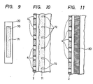
- the alignment problem described previously is further alleviated by modifying the meniscus forming member 20 in a manner as shown in Fig. 9.
- the member 20 is provided with a slit 70 having a width greater than the width of the slit 21 of the previous embodiment.
- a porous member 71 is fitted in the slit 70 and impregnated with the ink supplied from the rear chamber 8.
- the ink contained in the porous member 71 is contoured into a plurality of undulating surface portions under the influence of the air pressure distribution across the front surface of the porous member 71.
- the porous member 71 is provided with a plurality of conductive members 72 in positions corresponding to the main nozzles 4 as shown in Fig. 10. These conductive members are coupled to ground to serve as a common electrode for concentrating electric fields.
- the meniscus of the ink return rapidly to the original position when the electrical potential is removed.
- the rapid return property of the liquid's meniscus affects the minimum turn-off time of the printing head and hence the maximum operating frequency of the printer head.
- a pile of filaments 80 is fitted in the slit 21 of the slit member 20.
- filaments 80 One particular material that is satisfactory for filaments is glass fiber.
- the liquid in the rear chamber 8 passes through the interstices between the filaments 80 to the front surface of the pile to form a multitude of tiny meniscuses forming a general surface which undulates in accordance with the air pressure variations in the airflow chamber 9b.
- the filaments 80 have the effect of increasing the surface tension of the ink retained in the slit 21 to stabilize the surface undulation of the meniscus within a short period of time after removal of the applied potential.
- the slit member 20 of this embodiment is fabricated in a manner as shown in Fig.
- the base member 81 being formed with an elongated recess 85 which defines a slit with the adjacent edge of the base member 82 to hold therein the lower ends of the filaments 80.
- a frame 86 having an aperture 87 is mounted on the base members to allow passage of ink through the apertures 83, 84 and through the aperture 87 to the sides of the upper part of filaments 80.
- the holding member 89 On the frame 86 is disposed a pair of filament holding members 88 and 89, the holding member 89 being formed wth a recess 90 identical to the recess 85 to define a slit with the adjacent edge of the holding member 89 to hold the upper part of the filaments in the recess 85 so that the front surface of the pile of filaments 80 is made flush with the upper surface of the holding members 88 and 89.
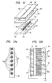
- FIG. 13a and 13b A modification of the embodiment of Fig. 11 is illustrated in Figs. 13a and 13b.
- the individual electrodes 6 are replaced with a thin elongated electrode 95 having a plurality of apertures 91 each encircling each main nozzle 4 and the filament pile 80 is provided with a plurality of conductive filaments 92 which are located in positions corresponding to the centers of the apertures 91 to produce intensified electric fields.
- the conductive filaments 92 are respectively coupled to the individual signal sources 93 to serve as individual signal electrodes, while the electrode 90 is coupled to ground to serve as a common electrode.
- Fig. 14 An alternative embodiment is further shown in Fig. 14 in which the slit member 20 comprises a frame 100 and a mesh 101 attached thereto.
- the mesh structure 101 is in contact with the ink in the opening 102 to serve as a meniscus forming surface on which a multitude of meniscuses are formed and retained with a holding power sufficient to return the meniscus to the original position after ejection of droplets.
- the opening 102 has a width greater than the diameter of the main nozzle 4 to facilitate alignment with the latter.
- Figs. 15 and 16 illustrate an embodiment in which the number of electrodes is greatly increased.
- a common electrode 110 of elongated configuration having a plurality of apertures 111 corresponding to the main nozzles 4 formed in the underlying plate 2, the electrode 110 being coupled electrically to ground.
- a first group of conductive filaments 112 and a second group of nonconductive filaments 113 extend transverse to the slit member 20 from opposite sides of rear block 7 so that filaments of each group are interleaved one-for-one with each other.
- the conductive filaments 112 connect to respective terminals to which individual signals are applied.
- the nonconductive filaments 113 not only provide the effect of insulation between conductive filaments 112 and but produce a combined effect of increasing the surface tension of the liquid with the conductive filaments 112 to improve the The turn-off characteristic of the printing head.
- the filaments 113 could also be formed of a conductive material. In this case the filaments 113 are coupled to ground to serve as a shield between adjacent conductive filaments 112.
Landscapes
- Particle Formation And Scattering Control In Inkjet Printers (AREA)
Abstract
Description
- The present invention relates generally to nonimpact printing heads, and in particular to an ink jet printing head having a plurality of nozzles in which the combined effects of air pressure gradient and electric potential gradient are utilized to discharge a controlled number of jet streams of ink droplets.
- The ink jet printing head shown and described in Japanese Patent Application 56-8428 filed January 1, 1981 comprises an airflow chamber having a single air-liquid nozzle through which a combined stream of air and ink droplets is discharged toward a writing surface. The airflow chamber is connected to a pressurized air supply source for causing an airstream to make a sharp turn at the entry into the air-liquid nozzle, creating a sharp pressure gradient in the liquid discharge path. A liquid nozzle, connected to an ink supply, is axially aligned with the air-liquid nozzle. By the action of the pressure gradient the meniscus of ink at the liquid nozzle is convexed toward the air-liquid nozzle. An electrode is provided for establishing an electric field between the air-liquid nozzle and the convexed meniscus of the liquid to cause it to extend toward the air-liquid nozzle by electrostic attraction and to be torn apart into a droplet which is carried by the airstream and discharged through the air-liquid nozzle.
- To make the operating speed of the nonimpact printer consistent with the high-speed data handling capability of the apparatus with which it is to be associated, it is desired that the printing head have a row of plural nozzles to enable simultaneous printing of dots. One approach would be to provide a plurality of liquid nozzles. For proper operation of the printer head the liquid nozzle must be aligned with one-to-one correspondence with the air-liquid nozzles with a high degree of precision. Because of close tolerances this alignment is extremely difficult to achieve.
- An object of the invention is therefore to provide a multi-nozzle ink jet printing head which can be fabricated without close tolerances, while at the same time providing a printing head capable of responding high frequency input signals.
- The ink jet printing head of the invention comprises a nozzle plate having a plurality of nozzles successively arranged in a row. An airflow chamber, located behind the nozzle plate, is in communication with a source of pressurized air for allowing an airstream to make sharp turns at the entry into the nozzles to produce a plurality of sharp pressure gradients. A liquid chamber, connected to a source of ink, is located behind the airflow chamber. Between the air and liquid chambers is located a meniscus forming member for causing the ink to form at least one meniscus by surface tension over an area extending parallel with the row of nozzles. Under the influence of pressure gradients the meniscus of the ink is contoured into a plurality of surface portions convexed toward the nozzles. Electric fields are selectively established between the nozzles and the correspoding convexed surface portions for causing the convexed surface portions to extend toward the corresponding nozzles to be torn apart into droplets and discharged through the nozzles. Since the meniscus forming member can be easily manufactured to a high degree of precision, the alignment between it and the nozzles can be carried out without requiring highly skilled workers.
- The meniscus forming member comprises a slit member having a slit extending parallel with the row of nozzles, or a material having a multitude of interstices such as porous member, mesh structure or a pile of axially extending filaments for forming a plurality of meniscuses on the surface adjacent to the airflow chamber. Since the intersticed material have a sufficient amount of power to retain the ink so that the meniscuses return to the original positions within a small period of time after ejection of ink droplets.
- The invention will be described in further detail with reference to the accompanying drawings, in which:
- Fig. 1 is an illustration of an embodiment of the ink jet printer embodying the ink jet printing head of the present invention;
- Fig. 2 is a front view of the ink jet printing head of Fig. 1;
- Fig. 3 is a cross-sectional view taken along the line 3-3 of Fig. 1;
- Fig. 4 is a cross-sectional view taken along the line 4-4 of Fig. 1;
- .Fig. 5 is an enlarged view of an upper portion of the printing head of Fig. 1;
- Fig. 6a is a front view of a modified printing head which is useful for preventing adjacent air pressure distributions from interfering with each other;
- Fig. 6b is an axial cross-sectional view of the printing head of Fig. 6a;
- Fig. 7 is a front view of a further modified printing head useful for preventing adjacent electric fields from interfering with each other;
- Fig. 8 is a front view of a printing head which combines the concepts of Figs. 6 and 7;
- Fig. 9 is an illustration of a modified form of the slit member of Fig. 1;
- Fig. 10 is a cross-sectional view of the modified slit member having a plurality of additional electrodes embedded in the porous member;
- Fig. 11 is an illustration of a further modified form of the slit member;
- Fig. 12 is a perspective view illustrating the details of the slit member of Fig. 11;
- Figs. 13a and 13b are illustrations of a still further modification of the slit member of Fig. 1;
- Fig. 14 is an illustration of a still further modification of the slit member;
- Fig. 15 is an illustration of a further embodiment of the invention; and
- Fig. 16 is a partial cross-sectional view of the embodiment of Fig. 15.
- Referring now to Fig. 1, there is shown a preferred embodiment of the ink jet printer incorporating an embodiment of a multi-nozzle ink jet printing head 1 of the present invention. The printer comprises an
ink supply source 10 containingink 11 therein, a pressurizedair supply source 13 for supplying compressed air to theink supply source 10 through a regulatingvalve 12 and also to the ink jet printing head 1 throughconduit 14. - The printer head 1 shown in Fig. 1 represents a cross-section taken along the line A-A' of Fig. 2 and comprises a
front nozzle plate 2 having a plurality of main nozzles or air-liquid nozzles 4 successively arranged in a vertical row through which air and ink are ejected to a writing surface in a manner as will be described later. The inner wall of eachcommon nozzle 4 is lined with a conductive film to form anelectrode 6. Theelectrodes 6 are supplied with pulse signals from asignal source 15 to selectively establish one or more electric fields in eachmain nozzles 4. Thenozzle plate 2 is secured to arear block 7 of an insulative material which is formed aliquid holding chamber 8 and anair chamber 9 having an outer, airreservoir chamber portion 9a and an inner,airflow chamber portion 9b. The air and liquid chambers are separated by a dividing wall ormeniscus forming member 20 which, in this embodiment, takes the form of a slit member formed with aslit 21 having a width approximately equal to the diameter of eachmain nozzle 4, theslit 21 extending parallel with the row ofmain nozzles 4. Theliquid chamber 8 is in communication with theink supply source 10 viaconductive tube 16 which is electrically coupled to ground. The width of theslit 21 is determined in relation to the viscocity and surface tension of the ink to render its meniscus susceptible both to air pressure gradient and electric field potential gradient. As illustrated in Fig. 2, theelectrodes 5 are respectively coupled to one terminal of each ofsignal sources 15a,15bi - As seen from Figs. 3 and 4 the
slit 21 and air-liquid nozzles 5 are aligned with each other in the axial direction of the printer head. Because of the straight opening of theslit member 20, the latter can be manufactured easily to precision and axially aligned with the vertical row of themain nozzles 4 with a relaxed tolerance. - The air supplied to the printer head 1 is buffered by the outer
reservoir chamber portion 9a and fills the innerair chamber portion 9b with a laminar airflow. This airflow sharply bends at the entry into each main and auxiliary nozzle and escapes therethrough to a writing surface. This sharp bending of airstream produces a high air pressure on the meniscus of the ink at theslit 21 creating an air pressure gradient which increases as a function of distance from theslit 21. - The regulating
valve 12 is manually adjusted in the absence of signals to theelectrodes 6 so that the liquid pressure in theslit 21 is statically balanced against the combined force of the air pressure acting on the meniscus on theslit 21 and its surface tension until the meniscus is contoured by virtue of the pressure gradients into a plurality of forwardly convexedsurfaces 30 each located directly behind eachmain nozzle 4 with rearwardlyconcaved surfaces 31 formed between them as clearly shown in Fig. 5. When electric potential is applied to a given electrode the convexed meniscus portion behind that electrode is electrostatically charged with respect thereto and is pulled forward. Since the electric field has an increasing potential gradient toward the nozzle plate and tends to concentrate on the forward end of the convexed meniscus, the pulling force increases as the meniscus is extended forward. Therefore, in response to the application of a potential the portion of ink just behind the biased electrode is rapidly pulled forward and torn apart into a droplet under the combined effects of electrical potential gradient and air pressure gradient. The droplet is carried by the airstream and expelled at a high speed through the electrically biased nozzle to a recording sheet. - In a practical embodiment of the invention, the air pressure acting on the meniscus is preferably in a range from 0.03 to 0.2 kilograms/cm2. With the air pressure of this range, an air speed of about 40 to 150 meters/second is attained at the discharge end of each nozzle. A preferred value of the diameter of each air-liquid
main nozzle 4 is approximately 250 micrometers or less. - Two
air nozzles 5 are additionally disposed one on each end of the vertical row. The purpose of theair nozzles 5 is to permit the portion of air above and below the row of main nozzles to escape throughnozzles 5 so that all the main nozzles have an equal air pressure distribution. Otherwise, the main nozzles disposed on the end of the row would have a pressure distribution differing from the distribution of other main nozzles, resulting in a skewed trajectory of the ink droplets from such nozzles. In a preferred embodiment of the present invention, the spacing Sl between each end of theslit 21 and the main nozzle adjacent thereto is greater than twice the diameter D of themain nozzle 4 and is greater than one-half the center-to-center spacing S2 between adjacent main nozzles. - Consider now the effect of interference between adjacent main nozzles. When a given convexed surface portion is pulled forward in response to the application of a potential to the associated electrode, it tends to drag some of the liquid from adjacent convexed surfaces causing them to sag in convexity. This is considered to be attributed partly to the shortage of ink to be replenished.
- To this end, the axial dimension or depth T of the
slit 21 is preferably less than 3/2 of the center-to-center spacing S2. With this quantitative relationship the flow resistance to the liquid in theslit 21 can be minimized o increasing the amount of ink to be replenished from therear chamber 8 to a satisfactory level. - The problem of liquid shortage in the
slit 21 could also be eliminated by forming a plurality ofauxiliary air nozzles 40 in thenozzle plate 2 so that eachauxiliary nozzle 40 is disposed between adjacentmain nozzles 4 as illustrated in Figs. 6a and 6b. The provision of such air nozzles causes the portions of meniscus behind them to be contoured into forwardly convexed surfaces as shown in Fig. 6b. Assume for purposes of explanation that a potential is applied to the electrode 6a of air-liquid nozzle 4a in Fig. 6b, the convexed meniscus portions behind adjacent air nozzles 40a, 40a will sag to a flat level. It will be seen that air nozzles 40a, 40a act as a buffer between adjacentmain nozzles 4. Each of theadditional air nozzles 40 has preferably a diameter smaller than the diameter of the air-liquid nozzle 4. - Mutual interference alsooccurs between adjacent electrical fields. This can be avoided by forming a plurality of additional
elongated shielding electrodes 50 as shown in Fig. 7, each of the shieldingelectrodes 50 being located between adjacentmain electrodes 6 and electrically connected together to ground. - The interference in air pressure and field distribution could be eliminated by an embodiment shown in Fig. 8. This embodiment combines the arrangements of Figs. 6a, 6b and 7 so that
auxiliary air nozzles 40 has their inner walls lined withcylindrical shield electrodes 60 which are electrically coupled to ground. - The alignment problem described previously is further alleviated by modifying the
meniscus forming member 20 in a manner as shown in Fig. 9. In this modification themember 20 is provided with aslit 70 having a width greater than the width of theslit 21 of the previous embodiment. Aporous member 71 is fitted in theslit 70 and impregnated with the ink supplied from therear chamber 8. In the same manner as described above the ink contained in theporous member 71 is contoured into a plurality of undulating surface portions under the influence of the air pressure distribution across the front surface of theporous member 71. In a preferred embodiment, theporous member 71 is provided with a plurality ofconductive members 72 in positions corresponding to themain nozzles 4 as shown in Fig. 10. These conductive members are coupled to ground to serve as a common electrode for concentrating electric fields. - For proper operation of the printing head of the invention, it is desirable that the meniscus of the ink return rapidly to the original position when the electrical potential is removed. The rapid return property of the liquid's meniscus affects the minimum turn-off time of the printing head and hence the maximum operating frequency of the printer head.
- For this purpose, a pile of
filaments 80, either formed of natural or artificial fibers, is fitted in theslit 21 of theslit member 20. One particular material that is satisfactory for filaments is glass fiber. The liquid in therear chamber 8 passes through the interstices between thefilaments 80 to the front surface of the pile to form a multitude of tiny meniscuses forming a general surface which undulates in accordance with the air pressure variations in theairflow chamber 9b. Thefilaments 80 have the effect of increasing the surface tension of the ink retained in theslit 21 to stabilize the surface undulation of the meniscus within a short period of time after removal of the applied potential. Theslit member 20 of this embodiment is fabricated in a manner as shown in Fig. 12 by comprising a pair ofbase members apertures base member 81 being formed with anelongated recess 85 which defines a slit with the adjacent edge of thebase member 82 to hold therein the lower ends of thefilaments 80. Aframe 86 having anaperture 87 is mounted on the base members to allow passage of ink through theapertures aperture 87 to the sides of the upper part offilaments 80. On theframe 86 is disposed a pair offilament holding members member 89 being formed wth arecess 90 identical to therecess 85 to define a slit with the adjacent edge of the holdingmember 89 to hold the upper part of the filaments in therecess 85 so that the front surface of the pile offilaments 80 is made flush with the upper surface of the holdingmembers - A modification of the embodiment of Fig. 11 is illustrated in Figs. 13a and 13b. In this modification the
individual electrodes 6 are replaced with a thinelongated electrode 95 having a plurality ofapertures 91 each encircling eachmain nozzle 4 and thefilament pile 80 is provided with a plurality ofconductive filaments 92 which are located in positions corresponding to the centers of theapertures 91 to produce intensified electric fields. Theconductive filaments 92 are respectively coupled to theindividual signal sources 93 to serve as individual signal electrodes, while theelectrode 90 is coupled to ground to serve as a common electrode. - An alternative embodiment is further shown in Fig. 14 in which the
slit member 20 comprises aframe 100 and amesh 101 attached thereto. Themesh structure 101 is in contact with the ink in theopening 102 to serve as a meniscus forming surface on which a multitude of meniscuses are formed and retained with a holding power sufficient to return the meniscus to the original position after ejection of droplets. Theopening 102 has a width greater than the diameter of themain nozzle 4 to facilitate alignment with the latter. - It is desirable that the number of individual electrodes should be made as large as possible to increase the operating speed of the printer head. Figs. 15 and 16 illustrate an embodiment in which the number of electrodes is greatly increased. To the
nozzle plate 2 is attached acommon electrode 110 of elongated configuration having a plurality ofapertures 111 corresponding to themain nozzles 4 formed in theunderlying plate 2, theelectrode 110 being coupled electrically to ground. A first group ofconductive filaments 112 and a second group ofnonconductive filaments 113 extend transverse to theslit member 20 from opposite sides ofrear block 7 so that filaments of each group are interleaved one-for-one with each other. Theconductive filaments 112 connect to respective terminals to which individual signals are applied. It is preferable that there is a plurality ofconductive filaments 112 that corresponds to eachmain nozzle 4 as shown in Fig. 16. Thenonconductive filaments 113 not only provide the effect of insulation betweenconductive filaments 112 and but produce a combined effect of increasing the surface tension of the liquid with theconductive filaments 112 to improve the The turn-off characteristic of the printing head. Thefilaments 113 could also be formed of a conductive material. In this case thefilaments 113 are coupled to ground to serve as a shield between adjacentconductive filaments 112.
Claims (16)
Applications Claiming Priority (10)
| Application Number | Priority Date | Filing Date | Title |
|---|---|---|---|
| JP56041195A JPS57156267A (en) | 1981-03-19 | 1981-03-19 | Ink jet recording device |
| JP41195/81 | 1981-03-19 | ||
| JP56062876A JPS57176173A (en) | 1981-04-24 | 1981-04-24 | Ink jet recorder |
| JP62876/81 | 1981-04-24 | ||
| JP56213473A JPS58112750A (en) | 1981-12-25 | 1981-12-25 | inkjet recording head |
| JP213473/81 | 1981-12-25 | ||
| JP212865/81 | 1981-12-29 | ||
| JP56212865A JPS58116159A (en) | 1981-12-29 | 1981-12-29 | Ink jet recording head |
| JP25312/82 | 1982-02-18 | ||
| JP57025312A JPS58142860A (en) | 1982-02-18 | 1982-02-18 | Ink jet recording head |
Publications (3)
| Publication Number | Publication Date |
|---|---|
| EP0061327A2 true EP0061327A2 (en) | 1982-09-29 |
| EP0061327A3 EP0061327A3 (en) | 1983-04-20 |
| EP0061327B1 EP0061327B1 (en) | 1985-11-27 |
Family
ID=27520721
Family Applications (1)
| Application Number | Title | Priority Date | Filing Date |
|---|---|---|---|
| EP82301440A Expired EP0061327B1 (en) | 1981-03-19 | 1982-03-19 | Ink jet printing head having a plurality of nozzles |
Country Status (3)
| Country | Link |
|---|---|
| US (1) | US4403228A (en) |
| EP (1) | EP0061327B1 (en) |
| DE (1) | DE3267647D1 (en) |
Cited By (2)
| Publication number | Priority date | Publication date | Assignee | Title |
|---|---|---|---|---|
| EP0212943A3 (en) * | 1985-08-13 | 1988-01-13 | Matsushita Electric Industrial Co., Ltd. | Ink jet recording apparatus |
| EP0376922A1 (en) * | 1985-08-13 | 1990-07-04 | Matsushita Electric Industrial Co., Ltd. | Ink jet recording apparatus |
Families Citing this family (33)
| Publication number | Priority date | Publication date | Assignee | Title |
|---|---|---|---|---|
| JPS58220758A (en) * | 1982-06-16 | 1983-12-22 | Matsushita Electric Ind Co Ltd | Inkjet recording device |
| US4620198A (en) * | 1985-11-20 | 1986-10-28 | Xerox Corporation | Multicolor ink jet printhead |
| JPH0234246U (en) * | 1988-08-29 | 1990-03-05 | ||
| DE4214555C2 (en) * | 1992-04-28 | 1996-04-25 | Eastman Kodak Co | Electrothermal ink print head |
| DE4214556A1 (en) * | 1992-04-28 | 1993-11-04 | Mannesmann Ag | ELECTROTHERMIC INK PRINT HEAD |
| US5294946A (en) * | 1992-06-08 | 1994-03-15 | Signtech Usa, Ltd. | Ink jet printer |
| DE69327762T2 (en) * | 1992-10-20 | 2000-07-06 | Canon K.K., Tokio/Tokyo | Color jet print head, its manufacturing process and associated color jet device |
| WO1995035212A1 (en) * | 1994-06-17 | 1995-12-28 | Natural Imaging Corporation | Electrohydrodynamic ink jet printer and printing method |
| JPH0834136A (en) * | 1994-07-22 | 1996-02-06 | Brother Ind Ltd | Image forming device |
| US5801721A (en) * | 1994-09-09 | 1998-09-01 | Signtech U.S.A. Ltd. | Apparatus for producing an image on a first side of a substrate and a mirror image on a second side of the substrate |
| US5796418A (en) * | 1995-04-12 | 1998-08-18 | Eastman Kodak Company | Page image and fault tolerance control apparatus for printing systems |
| US5856836A (en) * | 1995-04-12 | 1999-01-05 | Eastman Kodak Company | Coincident drop selection, drop separation printing method and system |
| DE69702079T2 (en) * | 1996-01-29 | 2000-10-05 | Nec Corp., Tokio/Tokyo | Inexpensive and simple electrostatic inkjet printhead |
| US6416157B1 (en) | 1998-09-30 | 2002-07-09 | Xerox Corporation | Method of marking a substrate employing a ballistic aerosol marking apparatus |
| US6265050B1 (en) | 1998-09-30 | 2001-07-24 | Xerox Corporation | Organic overcoat for electrode grid |
| US6511149B1 (en) | 1998-09-30 | 2003-01-28 | Xerox Corporation | Ballistic aerosol marking apparatus for marking a substrate |
| US6523928B2 (en) | 1998-09-30 | 2003-02-25 | Xerox Corporation | Method of treating a substrate employing a ballistic aerosol marking apparatus |
| JP2000108339A (en) * | 1998-09-30 | 2000-04-18 | Xerox Corp | Print head for ballistic aerosol printer |
| KR100839002B1 (en) * | 1998-09-30 | 2008-06-18 | 제록스 코포레이션 | Spray device for particulate marking material, deposition apparatus and deposition method for particulate marking material, substrate marking method and cartridge |
| US6416156B1 (en) | 1998-09-30 | 2002-07-09 | Xerox Corporation | Kinetic fusing of a marking material |
| US6340216B1 (en) | 1998-09-30 | 2002-01-22 | Xerox Corporation | Ballistic aerosol marking apparatus for treating a substrate |
| US6454384B1 (en) | 1998-09-30 | 2002-09-24 | Xerox Corporation | Method for marking with a liquid material using a ballistic aerosol marking apparatus |
| US6290342B1 (en) | 1998-09-30 | 2001-09-18 | Xerox Corporation | Particulate marking material transport apparatus utilizing traveling electrostatic waves |
| US6751865B1 (en) | 1998-09-30 | 2004-06-22 | Xerox Corporation | Method of making a print head for use in a ballistic aerosol marking apparatus |
| US6467862B1 (en) | 1998-09-30 | 2002-10-22 | Xerox Corporation | Cartridge for use in a ballistic aerosol marking apparatus |
| US6291088B1 (en) | 1998-09-30 | 2001-09-18 | Xerox Corporation | Inorganic overcoat for particulate transport electrode grid |
| US6328409B1 (en) | 1998-09-30 | 2001-12-11 | Xerox Corporation | Ballistic aerosol making apparatus for marking with a liquid material |
| US6328436B1 (en) | 1999-09-30 | 2001-12-11 | Xerox Corporation | Electro-static particulate source, circulation, and valving system for ballistic aerosol marking |
| US6293659B1 (en) | 1999-09-30 | 2001-09-25 | Xerox Corporation | Particulate source, circulation, and valving system for ballistic aerosol marking |
| US6786658B2 (en) * | 2000-05-23 | 2004-09-07 | Silverbrook Research Pty. Ltd. | Printer for accommodating varying page thicknesses |
| US6969160B2 (en) * | 2003-07-28 | 2005-11-29 | Xerox Corporation | Ballistic aerosol marking apparatus |
| JP2010246669A (en) * | 2009-04-14 | 2010-11-04 | Canon Inc | Liquid discharge head for inhaler and inhaler |
| EP3996924A4 (en) * | 2019-07-11 | 2023-07-19 | The Regents of the University of Michigan | Aerosol printing of specialty fluids |
Family Cites Families (9)
| Publication number | Priority date | Publication date | Assignee | Title |
|---|---|---|---|---|
| CA1055558A (en) * | 1974-09-26 | 1979-05-29 | Masayoshi Miura | Apparatus for applying liquid droplets to a surface by using a high speed laminar air flow to accelerate the same |
| US4031563A (en) * | 1976-01-29 | 1977-06-21 | The Mead Corporation | Jet drop recording head having an improved porous deflection ribbon |
| US4146900A (en) * | 1977-07-13 | 1979-03-27 | St. Regis Paper Company | Printing system |
| JPS5840512B2 (en) * | 1978-10-04 | 1983-09-06 | 株式会社リコー | inkjet recording device |
| US4167742A (en) * | 1978-05-01 | 1979-09-11 | The Mead Corporation | Damping means for an ink jet printing device |
| JPS54160242A (en) * | 1978-06-07 | 1979-12-18 | Ricoh Co Ltd | Bubble and choking remover of ink jet head |
| FR2448979B1 (en) * | 1979-02-16 | 1986-05-23 | Havas Machines | DEVICE FOR DEPOSITING INK DROPS ON A SUPPORT |
| US4272773A (en) * | 1979-05-24 | 1981-06-09 | Gould Inc. | Ink supply and filter for ink jet printing systems |
| EP0063853B1 (en) * | 1981-01-21 | 1986-03-12 | Matsushita Electric Industrial Co., Ltd. | Ink jet printing head utilizing pressure and potential gradients |
-
1982
- 1982-03-18 US US06/359,352 patent/US4403228A/en not_active Expired - Lifetime
- 1982-03-19 DE DE8282301440T patent/DE3267647D1/en not_active Expired
- 1982-03-19 EP EP82301440A patent/EP0061327B1/en not_active Expired
Cited By (3)
| Publication number | Priority date | Publication date | Assignee | Title |
|---|---|---|---|---|
| EP0212943A3 (en) * | 1985-08-13 | 1988-01-13 | Matsushita Electric Industrial Co., Ltd. | Ink jet recording apparatus |
| US4736212A (en) * | 1985-08-13 | 1988-04-05 | Matsushita Electric Industrial, Co., Ltd. | Ink jet recording apparatus |
| EP0376922A1 (en) * | 1985-08-13 | 1990-07-04 | Matsushita Electric Industrial Co., Ltd. | Ink jet recording apparatus |
Also Published As
| Publication number | Publication date |
|---|---|
| EP0061327B1 (en) | 1985-11-27 |
| US4403228A (en) | 1983-09-06 |
| DE3267647D1 (en) | 1986-01-09 |
| EP0061327A3 (en) | 1983-04-20 |
Similar Documents
| Publication | Publication Date | Title |
|---|---|---|
| US4403228A (en) | Ink jet printing head having a plurality of nozzles | |
| US4555717A (en) | Ink jet printing head utilizing pressure and potential gradients | |
| EP0192428B1 (en) | Thermal ink jet printer with droplet ejection by bubble collapse | |
| US4593296A (en) | Ink jet printer with gas evacuating arrangement | |
| US4636808A (en) | Continuous ink jet printer | |
| US4403234A (en) | Ink jet printing head utilizing pressure and potential gradients | |
| GB1571698A (en) | Ink jet printing | |
| US4514743A (en) | Ink jet filtered-chamber print head | |
| EP0212943A2 (en) | Ink jet recording apparatus | |
| GB2089735A (en) | Apparatus for deflecting ink drops | |
| EP0561205A2 (en) | Continuous ink jet catcher with improved screen structure | |
| US4268836A (en) | Ink jet printer having improved catcher | |
| US4023180A (en) | Dot printer with electrically propelled ink | |
| US20030179264A1 (en) | Auxiliary jetting device and ink jet recording device provided with auiliary jetting device | |
| US5400061A (en) | Ink-jet printer head | |
| CA1068328A (en) | Oblique multi-nozzle ink jet print head apparatus | |
| US4368477A (en) | Arrangement for a printing head in ink mosaic printing devices | |
| JPS58502191A (en) | Electrostatic ink jet device | |
| JPS5835153B2 (en) | Tentekiri Yuhenkousouchi | |
| CA1174723A (en) | Nozzle plate for ink jet print head | |
| JPS6117667B2 (en) | ||
| CA2193156A1 (en) | Two row flat face charging for high resolution printing | |
| US6767087B2 (en) | Inkjet head provided with deflecting electrodes for deflecting ejected ink droplets | |
| JPS58151257A (en) | Inkjet recording device | |
| US4275401A (en) | Method and apparatus for sorting and deflecting drops in an ink jet drop recorder |
Legal Events
| Date | Code | Title | Description |
|---|---|---|---|
| PUAI | Public reference made under article 153(3) epc to a published international application that has entered the european phase |
Free format text: ORIGINAL CODE: 0009012 |
|
| AK | Designated contracting states |
Designated state(s): DE FR GB |
|
| PUAL | Search report despatched |
Free format text: ORIGINAL CODE: 0009013 |
|
| AK | Designated contracting states |
Designated state(s): DE FR GB |
|
| 17P | Request for examination filed |
Effective date: 19830905 |
|
| GRAA | (expected) grant |
Free format text: ORIGINAL CODE: 0009210 |
|
| AK | Designated contracting states |
Designated state(s): DE FR GB |
|
| ET | Fr: translation filed | ||
| REF | Corresponds to: |
Ref document number: 3267647 Country of ref document: DE Date of ref document: 19860109 |
|
| PLBE | No opposition filed within time limit |
Free format text: ORIGINAL CODE: 0009261 |
|
| STAA | Information on the status of an ep patent application or granted ep patent |
Free format text: STATUS: NO OPPOSITION FILED WITHIN TIME LIMIT |
|
| 26N | No opposition filed | ||
| REG | Reference to a national code |
Ref country code: GB Ref legal event code: 746 Effective date: 19950224 |
|
| REG | Reference to a national code |
Ref country code: FR Ref legal event code: D6 |
|
| PGFP | Annual fee paid to national office [announced via postgrant information from national office to epo] |
Ref country code: DE Payment date: 20010312 Year of fee payment: 20 |
|
| PGFP | Annual fee paid to national office [announced via postgrant information from national office to epo] |
Ref country code: FR Payment date: 20010313 Year of fee payment: 20 |
|
| PGFP | Annual fee paid to national office [announced via postgrant information from national office to epo] |
Ref country code: GB Payment date: 20010314 Year of fee payment: 20 |
|
| REG | Reference to a national code |
Ref country code: GB Ref legal event code: IF02 |
|
| PG25 | Lapsed in a contracting state [announced via postgrant information from national office to epo] |
Ref country code: GB Free format text: LAPSE BECAUSE OF EXPIRATION OF PROTECTION Effective date: 20020318 |
|
| REG | Reference to a national code |
Ref country code: GB Ref legal event code: PE20 Effective date: 20020318 |