EP0061372A1 - Optische Einrichtung zur Echtzeit-Verstärkung der Strahlungsenergie eines Bündels - Google Patents
Optische Einrichtung zur Echtzeit-Verstärkung der Strahlungsenergie eines Bündels Download PDFInfo
- Publication number
- EP0061372A1 EP0061372A1 EP82400360A EP82400360A EP0061372A1 EP 0061372 A1 EP0061372 A1 EP 0061372A1 EP 82400360 A EP82400360 A EP 82400360A EP 82400360 A EP82400360 A EP 82400360A EP 0061372 A1 EP0061372 A1 EP 0061372A1
- Authority
- EP
- European Patent Office
- Prior art keywords
- strata
- network
- time
- beams
- index
- Prior art date
- Legal status (The legal status is an assumption and is not a legal conclusion. Google has not performed a legal analysis and makes no representation as to the accuracy of the status listed.)
- Granted
Links
- 230000003321 amplification Effects 0.000 title claims abstract description 12
- 238000003199 nucleic acid amplification method Methods 0.000 title claims abstract description 12
- 230000003287 optical effect Effects 0.000 title claims description 10
- 230000005855 radiation Effects 0.000 title 1
- 239000000463 material Substances 0.000 claims abstract description 39
- 238000006073 displacement reaction Methods 0.000 claims abstract description 17
- 230000005684 electric field Effects 0.000 claims abstract description 12
- 239000013078 crystal Substances 0.000 claims description 24
- 230000010363 phase shift Effects 0.000 claims description 11
- 230000001427 coherent effect Effects 0.000 claims description 7
- JSILWGOAJSWOGY-UHFFFAOYSA-N bismuth;oxosilicon Chemical compound [Bi].[Si]=O JSILWGOAJSWOGY-UHFFFAOYSA-N 0.000 claims 1
- 238000005286 illumination Methods 0.000 description 9
- 230000008878 coupling Effects 0.000 description 8
- 238000010168 coupling process Methods 0.000 description 8
- 238000005859 coupling reaction Methods 0.000 description 8
- 230000003993 interaction Effects 0.000 description 5
- 230000004044 response Effects 0.000 description 4
- 238000010586 diagram Methods 0.000 description 3
- 238000009792 diffusion process Methods 0.000 description 3
- 238000000034 method Methods 0.000 description 3
- 230000008901 benefit Effects 0.000 description 2
- 230000008569 process Effects 0.000 description 2
- 238000005086 pumping Methods 0.000 description 2
- 230000002787 reinforcement Effects 0.000 description 2
- XOTVYQNEABUPLI-UHFFFAOYSA-N [Si].[Bi]=O Chemical compound [Si].[Bi]=O XOTVYQNEABUPLI-UHFFFAOYSA-N 0.000 description 1
- 238000010521 absorption reaction Methods 0.000 description 1
- 238000012886 linear function Methods 0.000 description 1
- 230000000750 progressive effect Effects 0.000 description 1
- 230000001902 propagating effect Effects 0.000 description 1
- 239000004065 semiconductor Substances 0.000 description 1
- 230000001360 synchronised effect Effects 0.000 description 1
- 230000002123 temporal effect Effects 0.000 description 1
Images


Classifications
-
- G—PHYSICS
- G03—PHOTOGRAPHY; CINEMATOGRAPHY; ANALOGOUS TECHNIQUES USING WAVES OTHER THAN OPTICAL WAVES; ELECTROGRAPHY; HOLOGRAPHY
- G03H—HOLOGRAPHIC PROCESSES OR APPARATUS
- G03H1/00—Holographic processes or apparatus using light, infrared or ultraviolet waves for obtaining holograms or for obtaining an image from them; Details peculiar thereto
- G03H1/02—Details of features involved during the holographic process; Replication of holograms without interference recording
- G03H1/024—Hologram nature or properties
- G03H1/0248—Volume holograms
-
- G—PHYSICS
- G02—OPTICS
- G02F—OPTICAL DEVICES OR ARRANGEMENTS FOR THE CONTROL OF LIGHT BY MODIFICATION OF THE OPTICAL PROPERTIES OF THE MEDIA OF THE ELEMENTS INVOLVED THEREIN; NON-LINEAR OPTICS; FREQUENCY-CHANGING OF LIGHT; OPTICAL LOGIC ELEMENTS; OPTICAL ANALOGUE/DIGITAL CONVERTERS
- G02F1/00—Devices or arrangements for the control of the intensity, colour, phase, polarisation or direction of light arriving from an independent light source, e.g. switching, gating or modulating; Non-linear optics
- G02F1/01—Devices or arrangements for the control of the intensity, colour, phase, polarisation or direction of light arriving from an independent light source, e.g. switching, gating or modulating; Non-linear optics for the control of the intensity, phase, polarisation or colour
- G02F1/03—Devices or arrangements for the control of the intensity, colour, phase, polarisation or direction of light arriving from an independent light source, e.g. switching, gating or modulating; Non-linear optics for the control of the intensity, phase, polarisation or colour based on ceramics or electro-optical crystals, e.g. exhibiting Pockels effect or Kerr effect
- G02F1/05—Devices or arrangements for the control of the intensity, colour, phase, polarisation or direction of light arriving from an independent light source, e.g. switching, gating or modulating; Non-linear optics for the control of the intensity, phase, polarisation or colour based on ceramics or electro-optical crystals, e.g. exhibiting Pockels effect or Kerr effect with ferro-electric properties
- G02F1/0541—Devices or arrangements for the control of the intensity, colour, phase, polarisation or direction of light arriving from an independent light source, e.g. switching, gating or modulating; Non-linear optics for the control of the intensity, phase, polarisation or colour based on ceramics or electro-optical crystals, e.g. exhibiting Pockels effect or Kerr effect with ferro-electric properties using photorefractive effects
Definitions
- the invention relates to an optical device for real-time amplification of the radiant energy of a beam.
- an optical device on the path of the beam considered. It is known to use an optical device consisting of a recording medium in which the beam under consideration and a second reference beam interfere.
- This recording medium can be, for example, a photosensitive electro-optical material such as silicon bismuth oxide or BSO.
- a network of fringes created by the interference of the wave front coming from the object and the reference wave front, induces, in real time, at the time of the registration of the material, a network of index strata, constituting a hologram characteristic of the object wavefront. It diffracts part of the energy of the incident reference wavefront according to a diffracted wave whose wavefront is isomorphic to the object wavefront.
- the intensity of the directly transmitted object beam is increased, in practice, by a factor of 2 to 3 in the presence of the reference beam which acts, under these conditions, as a pumping wave.
- the reference beam which acts, under these conditions, as a pumping wave.
- only recording by zero-field diffusion satisfies the optimal conditions for this wave coupling. These conditions are no longer verified when an electric field is applied which allows a high index variation to be induced.
- the invention relates to these techniques for coupling waves in materials allowing the registration of dynamic holograms by variation of photoinduced index.
- the proposed device ensures under optimal conditions, in the presence of a transverse field applied to the material considered, the transfer of energy from the reference wave to the object wave. To achieve these conditions, we introduce a displacement of inter fringes ferences. As such, this device allows the coherent amplification of the radiant energy of a beam.
- the subject of the invention is therefore an optical device for real-time amplification of the radiant energy of a beam comprising a photosensitive recording material within which is inscribed in real time, a network of strata of photoinduced index obtained thanks to the interference in the volume of this material of an incident object beam coming from a coherent source, and of a reference beam which is coherent to it, an energy transfer taking place between this reference beam and this object beam, an electric field orthogonal to the plane of the strata, being applied across the boundaries of this material; device mainly characterized in that mechanical means allow a displacement of this photosensitive material during the time of registration of the material, the phase shift between the network of index strata and the network of interference fringes of these two beams being thus maintained constant and equal to tr / 2.
- the device proposed in this patent is based on dynamic helographic inscription on a photosensitive support operating by variation of photoinduced index.
- the operation is illustrated diagrammatically in FIG. 1.
- the signal wavefront ⁇ o diffracted by the object interferes coherently with a plane wave referenced I: R.
- the network of interference fringes is registered in real time in the material in the form of a variation of photoinduced index.
- the coupling of waves results in a transfer of energy from the reference beam to the signal wave after crossing the crystal.
- the intensity of the object beam is therefore increased in the presence of the reference beam which under these conditions acts as a pumping wave.
- I o and I R being the light intensities of the beams.
- the reference wave diffracted by the phase grating generates a wave ⁇ d identical to the signal wave.
- a thick single crystal 1 cut from an electro-optic photoconductive material, for example BSO.
- this object wave interferes with a reference wave 3, with a plane wavefront ⁇ R.
- the network of interference fringes 11 thus created generates, in real time, in the crystal, a network of strata of index 12, after a writing time T.
- This network of strata diffracts part of the energy of the reference wave 3 into a diffracted wave 4 whose wave front is isomorphic from the object wave front front o .
- the photo-induced network can be exactly phase shifted; with respect to the incident illumination network, which results in obtaining a diffracted wave 4 strictly superimposed on the transmitted object wave 5; everything happens as if the transmitted object wave was enriched with a fraction of the energy of the reference wave. If the thickness of the crystal concerned by the interference of the two beams is large, of the order of 1 cm, the transmitted object beam can be considerably reinforced, by a factor of 2 to 3.
- this reinforced object wave again interferes with the reference beam, which accentuates the modulation of the fringes, and creates a contribution of energy on the object beam a little more important, and thus of near close, throughout the thickness of the crystal in which the object and reference beams interfere, because the new photo-induced network is always in phase with the main network, thanks to the phase shift of; between the interference network and the index network.
- the fringe modulation rate is greater than on the input face, as shown in Figure 2 in b.
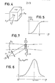
- the straight line 41 represents the intensity of the directly transmitted object beam, in the absence of the reference beam 3. This intensity is constant from time 0 when the incident object beam arrives on the crystal BSO .
- Curve 42 shows the establishment at the end of time T of the diffracted object beam in the case of the present invention, with an intensity two to three times greater than that of the directly transmitted object beam; the energy of this diffracted beam being taken from the reference beam.
- the crystal 1 may or may not be subjected to a transverse electric field, in the direction of the axis OX in FIG. 1, the phase shift of between the interference network and the index network is established automa tically, but the efficiency of the amplification phenomenon is greater the higher the applied electric field, typically between 10 and 20 kV.cm -1 .
- This saturation entry of the index network from the interference fringe network is not instantaneous and requires a certain time T , typically 100 ms, and the same is true for the erasure of the network.
- the preferred orientation of the single crystal with respect to the direction of the electric field which is the x-axis is that which is shown in FIG. 4, that is to say perpendicular to the faces of the shape 001 of the crystal.
- the incidence of the beams on the faces of the ⁇ 110 ⁇ or ⁇ 110 ⁇ shape and which determines the pitch of the fringes, is optimal around 20 to 30 °, for example + 20 ° for the object beam, - 20 ° for the reference beam.
- the time constants T used for the transfer of energy from the reference beam to the object beam are practically independent of the ratio of the intensities of the incident beams, reference and object, T varies from 50 to 100 ms when this ratio varies from 1 at 1000.
- the amplification coefficient obtained on the transmitted object beam is also independent of this ratio as soon as it is greater than 10 and is a non-linear function of the electric field applied to the crystal when this field exceeds a threshold value of 10 kV.cm -1 . It is also technologically difficult to work at more than 20 kV.cm -1 .
- a recording by "diffusion" with null field E 0; ⁇ ⁇ 0.5 to 1 ⁇ m.
- the present device makes it possible to take advantage of the high index variation due to the recording under the applied field by introducing a suitable displacement of the interference fringes during the recording time of the material.
- ⁇ n the variation of index in the medium.
- ⁇ n can be broken down into ⁇ n 1 and ⁇ n 2 ; ⁇ n 1 being in phase with the illumination and A n 2 in quadrature with this illumination.
- ⁇ n 2 is the component which allows a wave coupling such that there is an optimum energy transfer.
- We. can achieve this phase shift using a mirror associated with a piezoelectric transducer for example, or using an acousto-optical device according to the necessary speeds.
- An embodiment of this phase shift with a mirror 24 associated with a piezoelectric transducer is illustrated in FIG. 9.
- This mirror 24 is made, for example, with a piezoelectric material having the form of a film and one of the faces of which is metallized; it can also be one of the control electrodes 23 as shown in FIG. 9.
- the sawtooth signal makes it possible to move the strata which appears to be regular.
- the amplitude of this signal must allow a displacement of an integer number of fringes.
- the curve in Figure 10 represents the displacement of the mirror. If ⁇ is the wavelength of the reflected beam, a displacement of the mirror being amplified by two at the level of the beam. The phase shift represented by this signal is therefore equal to k .
- a rapid displacement of interference fringes is easily obtained with an acousto-optical device.
- An acousto-optic sliding phenomenon is then used for continuous operation; the acousto-optical material being driven by a frequency signal F.
- the propagation of an acoustic wave in a refractive medium is reflected on the optical index of this medium by a synchronous undulatory disturbance whose origin is in the modulation brought to the local density of matter by the local distribution of pressures .
- phase modulator or the acousto-optical device on the incident object beam and no longer on the reference beam.
Landscapes
- Physics & Mathematics (AREA)
- General Physics & Mathematics (AREA)
- Nonlinear Science (AREA)
- Chemical & Material Sciences (AREA)
- Engineering & Computer Science (AREA)
- Ceramic Engineering (AREA)
- Crystallography & Structural Chemistry (AREA)
- Optics & Photonics (AREA)
- Holo Graphy (AREA)
- Non-Silver Salt Photosensitive Materials And Non-Silver Salt Photography (AREA)
Applications Claiming Priority (2)
| Application Number | Priority Date | Filing Date | Title |
|---|---|---|---|
| FR8105135 | 1981-03-13 | ||
| FR8105135A FR2501872A1 (fr) | 1981-03-13 | 1981-03-13 | Dispositif optique d'amplification en temps reel de l'energie radiante d'un faisceau |
Publications (2)
| Publication Number | Publication Date |
|---|---|
| EP0061372A1 true EP0061372A1 (de) | 1982-09-29 |
| EP0061372B1 EP0061372B1 (de) | 1984-11-14 |
Family
ID=9256247
Family Applications (1)
| Application Number | Title | Priority Date | Filing Date |
|---|---|---|---|
| EP82400360A Expired EP0061372B1 (de) | 1981-03-13 | 1982-03-02 | Optische Einrichtung zur Echtzeit-Verstärkung der Strahlungsenergie eines Bündels |
Country Status (5)
| Country | Link |
|---|---|
| US (1) | US4505536A (de) |
| EP (1) | EP0061372B1 (de) |
| JP (1) | JPS57161878A (de) |
| DE (1) | DE3261219D1 (de) |
| FR (1) | FR2501872A1 (de) |
Cited By (1)
| Publication number | Priority date | Publication date | Assignee | Title |
|---|---|---|---|---|
| FR2608792A1 (fr) * | 1986-12-23 | 1988-06-24 | Thomson Csf | Dispositif d'amplification de signaux optiques a milieu photosensible |
Families Citing this family (15)
| Publication number | Priority date | Publication date | Assignee | Title |
|---|---|---|---|---|
| GB8610027D0 (en) * | 1986-04-24 | 1986-05-29 | British Petroleum Co Plc | Phase conjugate reflecting media |
| US4703992A (en) * | 1986-05-27 | 1987-11-03 | Rockwell International Corporation | Laser beam cleanup by photorefractive two-way mixing |
| US4761059A (en) * | 1986-07-28 | 1988-08-02 | Rockwell International Corporation | External beam combining of multiple lasers |
| US4784473A (en) * | 1987-03-02 | 1988-11-15 | United States Of America As Represented By The Secretary Of The Navy | Ferroelectric optical switching |
| US4877297A (en) * | 1988-04-29 | 1989-10-31 | Rockwell International Corporation | Reconfigurable 0ptical interconnect using dynamic hologram |
| FR2674642B1 (fr) * | 1991-03-25 | 1993-12-03 | Gaz De France | Fibre optique a reseau de bragg interne variable et ses applications. |
| FR2681988A1 (fr) * | 1991-09-27 | 1993-04-02 | Thomson Csf | Laser de puissance a deflexion. |
| FR2696014B1 (fr) * | 1992-09-18 | 1994-11-04 | Thomson Csf | Miroir à conjugaison de phase. |
| US5422873A (en) * | 1993-03-25 | 1995-06-06 | California Institute Of Technology | Multiplexing and selective updatable fixing and erasing of volume holograms in photorefractive media and second harmonic generation in photorefractive media by optically induced periodic poling |
| FR2707447B1 (fr) * | 1993-07-09 | 1995-09-01 | Thomson Csf | Dispositif de visualisation couleurs. |
| US5665493A (en) * | 1995-10-03 | 1997-09-09 | Sri International | Gated recording of holograms using rare-earth doped ferroelectric materials |
| EP0864157A1 (de) * | 1995-11-28 | 1998-09-16 | Sri International | Zweistufige gesteuerte aufzeichnung von hologrammen in fotorefraktiven materialien unter verwendung von cw-lasern |
| FR2755516B1 (fr) | 1996-11-05 | 1999-01-22 | Thomson Csf | Dispositif compact d'illumination |
| US5978108A (en) * | 1997-03-12 | 1999-11-02 | Stanford Research Institute | Two-step gated holographic recording in photorefractive materials using cw lasers |
| FR2819061B1 (fr) * | 2000-12-28 | 2003-04-11 | Thomson Csf | Dispositif de controle de polarisation dans une liaison optique |
Family Cites Families (1)
| Publication number | Priority date | Publication date | Assignee | Title |
|---|---|---|---|---|
| FR2362466A1 (fr) * | 1976-08-19 | 1978-03-17 | Thomson Csf | Cellule d'enregistrement holographique, memoire et dispositif de calcul optique utilisant une telle cellule |
-
1981
- 1981-03-13 FR FR8105135A patent/FR2501872A1/fr active Granted
-
1982
- 1982-03-02 US US06/354,049 patent/US4505536A/en not_active Expired - Lifetime
- 1982-03-02 EP EP82400360A patent/EP0061372B1/de not_active Expired
- 1982-03-02 DE DE8282400360T patent/DE3261219D1/de not_active Expired
- 1982-03-11 JP JP57038828A patent/JPS57161878A/ja active Granted
Non-Patent Citations (5)
| Title |
|---|
| APPLIED OPTICS, vol. 15, no. 8, août 1976, NEW YORK (US), S. SU et al.: "Refractive index profile and physical process determination in thick gratings in electro-optical crystals", pages 1947-1952 * |
| JOURNAL OF APPLIED PHYSICS, vol. 43, no. 3, mars 1972, NEW YORK (US), D. STAEBLER et al.: "Coupled wave analysis of holographic storage in LiNbO3", pages 1042-1049 * |
| JOURNAL OF APPLIED PHYSICS, vol. 51, no. 3, mars 1980, NEW YORK (US), J. FEINBERG et al.: "Photorefractive effects and light charge migration in Barium Titanate", pages 1297-1305 * |
| JOURNAL OF THE OPTICAL SOCIETY OF AMERICA, vol. 65, no. 6, juin 1975, NEW YORK (US), S. CASE: "Coupled ware theory for multiply exposed thick holographic gratings", pages 724-729 * |
| OPTICS AND LASER TECHNOLOGY, vol. 11, no. 2, avril 1979, Ed. IPC, HAYWARDS HEATH (GB), V. MARKOV et al.: "Dynamic holography and optical image processing", pages 95-99 * |
Cited By (3)
| Publication number | Priority date | Publication date | Assignee | Title |
|---|---|---|---|---|
| FR2608792A1 (fr) * | 1986-12-23 | 1988-06-24 | Thomson Csf | Dispositif d'amplification de signaux optiques a milieu photosensible |
| EP0275768A1 (de) * | 1986-12-23 | 1988-07-27 | Thomson-Csf | Verstärkungsvorrichtung für optische Signale mit lichtempfindlichem Medium |
| US4847521A (en) * | 1986-12-23 | 1989-07-11 | Thomson-Csf | Device for the amplification of light-sensitive |
Also Published As
| Publication number | Publication date |
|---|---|
| US4505536A (en) | 1985-03-19 |
| FR2501872B1 (de) | 1984-01-20 |
| DE3261219D1 (en) | 1984-12-20 |
| JPS57161878A (en) | 1982-10-05 |
| EP0061372B1 (de) | 1984-11-14 |
| JPH0322963B2 (de) | 1991-03-28 |
| FR2501872A1 (fr) | 1982-09-17 |
Similar Documents
| Publication | Publication Date | Title |
|---|---|---|
| EP0061372B1 (de) | Optische Einrichtung zur Echtzeit-Verstärkung der Strahlungsenergie eines Bündels | |
| EP0067082B1 (de) | Kohärente Strahlungsquelle zur Erzeugung eines in der Fortpflanzungsrichtung regelbaren Strahlenbündels | |
| EP0275768B1 (de) | Verstärkungsvorrichtung für optische Signale mit lichtempfindlichem Medium | |
| EP0112732B1 (de) | Nichtlineare Kopplungsanordnung in integrierter Optik und parametrischer Oszillator, der eine solche Vorrichtung umfasst | |
| EP3009878B1 (de) | Elektrooptischer phasenmodulator | |
| EP0061360B1 (de) | Optische Vorrichtung zum Unterhalten eines in einem Monomode-Wellenleiter zirkulierenden Strahlungsenergieimpulses; Gyrometer und Hydrophon mit einer solchen Vorrichtung | |
| EP0138668B1 (de) | Einrichtung zur Aufnahme eines kohärenten Bildes in einem multimoden-optischen Hohlraum | |
| FR2558270A1 (fr) | Modulateur electro-optique interferentiel a haute sensibilite | |
| EP0053052B1 (de) | Interferometrische Einrichtung zur Echtzeit-Sichtbarmachung der Verformungen von schwingenden Gegenständen | |
| EP0095960A1 (de) | Einrichtung zum Speichern eines kohärenten Bildes in einem optischen Multimodalhohlraum | |
| EP0141739B1 (de) | Interferometrische Anordnung zum Messen einer Winkeldrehgeschwindigkeit | |
| EP0271411A2 (de) | Optische, bistabile Vorrichtung mit einem Photorefraktiven Kristall | |
| EP0299840B1 (de) | Korrelator mit optischer Faser | |
| EP0109886B1 (de) | Akusto-optische Anordnung zur Analyse von Spektren | |
| EP0306401B1 (de) | Frequenz-Wandler für den mittleren Infrarotbereich | |
| EP0098185B1 (de) | Beleuchtungseinrichtung für ein elektro-optisches Medium zur Aufzeichnung von Echtzeithologrammen | |
| EP0228312A1 (de) | Optoelektronischer Schwellenleistungsschalter und sein Steuerungsverfahren | |
| FR2535072A1 (fr) | Dispositif optique de dephasage et application a un generateur laser | |
| FR2669123A1 (fr) | Deflecteur de faisceau lumineux comprenant un reseau de bragg. | |
| JPS63147140A (ja) | 音響光学素子 | |
| FR2751094A1 (fr) | Dispositif de controle d'impulsions lumineuses par un dispositif programmable acousto-optique | |
| FR2904735A1 (fr) | Dispositif de deflexion acousto-optique. | |
| EP0486356A1 (de) | Piezoelektrisch betriebener zweidimensionaler Raumlichtmodulator mit einem Bragg-Gitter | |
| FR2757647A1 (fr) | Modulateur electrooptique de faisceau lumineux | |
| FR2791186A1 (fr) | Source laser a faisceau de sortie sans distorsions |
Legal Events
| Date | Code | Title | Description |
|---|---|---|---|
| PUAI | Public reference made under article 153(3) epc to a published international application that has entered the european phase |
Free format text: ORIGINAL CODE: 0009012 |
|
| AK | Designated contracting states |
Designated state(s): DE GB NL |
|
| 17P | Request for examination filed |
Effective date: 19821014 |
|
| GRAA | (expected) grant |
Free format text: ORIGINAL CODE: 0009210 |
|
| AK | Designated contracting states |
Designated state(s): DE GB NL |
|
| REF | Corresponds to: |
Ref document number: 3261219 Country of ref document: DE Date of ref document: 19841220 |
|
| PLBE | No opposition filed within time limit |
Free format text: ORIGINAL CODE: 0009261 |
|
| STAA | Information on the status of an ep patent application or granted ep patent |
Free format text: STATUS: NO OPPOSITION FILED WITHIN TIME LIMIT |
|
| 26N | No opposition filed | ||
| PGFP | Annual fee paid to national office [announced via postgrant information from national office to epo] |
Ref country code: NL Payment date: 19940331 Year of fee payment: 13 |
|
| REG | Reference to a national code |
Ref country code: GB Ref legal event code: 746 Effective date: 19950214 |
|
| PG25 | Lapsed in a contracting state [announced via postgrant information from national office to epo] |
Ref country code: NL Effective date: 19951001 |
|
| NLV4 | Nl: lapsed or anulled due to non-payment of the annual fee |
Effective date: 19951001 |
|
| PGFP | Annual fee paid to national office [announced via postgrant information from national office to epo] |
Ref country code: GB Payment date: 19970218 Year of fee payment: 16 Ref country code: DE Payment date: 19970218 Year of fee payment: 16 |
|
| PG25 | Lapsed in a contracting state [announced via postgrant information from national office to epo] |
Ref country code: GB Free format text: LAPSE BECAUSE OF NON-PAYMENT OF DUE FEES Effective date: 19980302 |
|
| GBPC | Gb: european patent ceased through non-payment of renewal fee |
Effective date: 19980302 |
|
| PG25 | Lapsed in a contracting state [announced via postgrant information from national office to epo] |
Ref country code: DE Free format text: LAPSE BECAUSE OF NON-PAYMENT OF DUE FEES Effective date: 19981201 |