EP0061396A1 - Drehbare Vorrichtung zum Durchtrennen eines verbrannten Kernbrennstoff enthaltenden Rohrbündels - Google Patents
Drehbare Vorrichtung zum Durchtrennen eines verbrannten Kernbrennstoff enthaltenden Rohrbündels Download PDFInfo
- Publication number
- EP0061396A1 EP0061396A1 EP82400491A EP82400491A EP0061396A1 EP 0061396 A1 EP0061396 A1 EP 0061396A1 EP 82400491 A EP82400491 A EP 82400491A EP 82400491 A EP82400491 A EP 82400491A EP 0061396 A1 EP0061396 A1 EP 0061396A1
- Authority
- EP
- European Patent Office
- Prior art keywords
- cutting
- cutting means
- teeth
- rotor
- bundle
- Prior art date
- Legal status (The legal status is an assumption and is not a legal conclusion. Google has not performed a legal analysis and makes no representation as to the accuracy of the status listed.)
- Granted
Links
- 239000000446 fuel Substances 0.000 title description 6
- 239000003758 nuclear fuel Substances 0.000 claims abstract 2
- 238000006073 displacement reaction Methods 0.000 description 4
- 238000000926 separation method Methods 0.000 description 3
- 238000010008 shearing Methods 0.000 description 3
- IJGRMHOSHXDMSA-UHFFFAOYSA-N Atomic nitrogen Chemical compound N#N IJGRMHOSHXDMSA-UHFFFAOYSA-N 0.000 description 2
- 239000000428 dust Substances 0.000 description 2
- 239000007789 gas Substances 0.000 description 2
- 240000008042 Zea mays Species 0.000 description 1
- 238000011109 contamination Methods 0.000 description 1
- 238000004090 dissolution Methods 0.000 description 1
- 238000010410 dusting Methods 0.000 description 1
- 230000000694 effects Effects 0.000 description 1
- 239000002184 metal Substances 0.000 description 1
- 229910052757 nitrogen Inorganic materials 0.000 description 1
- 230000000750 progressive effect Effects 0.000 description 1
- 230000002285 radioactive effect Effects 0.000 description 1
- 238000012958 reprocessing Methods 0.000 description 1
- 230000000630 rising effect Effects 0.000 description 1
- 230000036346 tooth eruption Effects 0.000 description 1
Images



Classifications
-
- G—PHYSICS
- G21—NUCLEAR PHYSICS; NUCLEAR ENGINEERING
- G21C—NUCLEAR REACTORS
- G21C19/00—Arrangements for treating, for handling, or for facilitating the handling of, fuel or other materials which are used within the reactor, e.g. within its pressure vessel
- G21C19/34—Apparatus or processes for dismantling nuclear fuel, e.g. before reprocessing ; Apparatus or processes for dismantling strings of spent fuel elements
- G21C19/36—Mechanical means only
-
- Y—GENERAL TAGGING OF NEW TECHNOLOGICAL DEVELOPMENTS; GENERAL TAGGING OF CROSS-SECTIONAL TECHNOLOGIES SPANNING OVER SEVERAL SECTIONS OF THE IPC; TECHNICAL SUBJECTS COVERED BY FORMER USPC CROSS-REFERENCE ART COLLECTIONS [XRACs] AND DIGESTS
- Y02—TECHNOLOGIES OR APPLICATIONS FOR MITIGATION OR ADAPTATION AGAINST CLIMATE CHANGE
- Y02E—REDUCTION OF GREENHOUSE GAS [GHG] EMISSIONS, RELATED TO ENERGY GENERATION, TRANSMISSION OR DISTRIBUTION
- Y02E30/00—Energy generation of nuclear origin
- Y02E30/30—Nuclear fission reactors
-
- Y—GENERAL TAGGING OF NEW TECHNOLOGICAL DEVELOPMENTS; GENERAL TAGGING OF CROSS-SECTIONAL TECHNOLOGIES SPANNING OVER SEVERAL SECTIONS OF THE IPC; TECHNICAL SUBJECTS COVERED BY FORMER USPC CROSS-REFERENCE ART COLLECTIONS [XRACs] AND DIGESTS
- Y10—TECHNICAL SUBJECTS COVERED BY FORMER USPC
- Y10S—TECHNICAL SUBJECTS COVERED BY FORMER USPC CROSS-REFERENCE ART COLLECTIONS [XRACs] AND DIGESTS
- Y10S83/00—Cutting
- Y10S83/929—Particular nature of work or product
- Y10S83/93—Radioactive
-
- Y—GENERAL TAGGING OF NEW TECHNOLOGICAL DEVELOPMENTS; GENERAL TAGGING OF CROSS-SECTIONAL TECHNOLOGIES SPANNING OVER SEVERAL SECTIONS OF THE IPC; TECHNICAL SUBJECTS COVERED BY FORMER USPC CROSS-REFERENCE ART COLLECTIONS [XRACs] AND DIGESTS
- Y10—TECHNICAL SUBJECTS COVERED BY FORMER USPC
- Y10T—TECHNICAL SUBJECTS COVERED BY FORMER US CLASSIFICATION
- Y10T83/00—Cutting
- Y10T83/242—With means to clean work or tool
-
- Y—GENERAL TAGGING OF NEW TECHNOLOGICAL DEVELOPMENTS; GENERAL TAGGING OF CROSS-SECTIONAL TECHNOLOGIES SPANNING OVER SEVERAL SECTIONS OF THE IPC; TECHNICAL SUBJECTS COVERED BY FORMER USPC CROSS-REFERENCE ART COLLECTIONS [XRACs] AND DIGESTS
- Y10—TECHNICAL SUBJECTS COVERED BY FORMER USPC
- Y10T—TECHNICAL SUBJECTS COVERED BY FORMER US CLASSIFICATION
- Y10T83/00—Cutting
- Y10T83/444—Tool engages work during dwell of intermittent workfeed
- Y10T83/4645—With means to clamp work during dwell
-
- Y—GENERAL TAGGING OF NEW TECHNOLOGICAL DEVELOPMENTS; GENERAL TAGGING OF CROSS-SECTIONAL TECHNOLOGIES SPANNING OVER SEVERAL SECTIONS OF THE IPC; TECHNICAL SUBJECTS COVERED BY FORMER USPC CROSS-REFERENCE ART COLLECTIONS [XRACs] AND DIGESTS
- Y10—TECHNICAL SUBJECTS COVERED BY FORMER USPC
- Y10T—TECHNICAL SUBJECTS COVERED BY FORMER US CLASSIFICATION
- Y10T83/00—Cutting
- Y10T83/485—Cutter with timed stroke relative to moving work
- Y10T83/494—Uniform periodic tool actuation
- Y10T83/496—With periodic lateral feed of tool or work
-
- Y—GENERAL TAGGING OF NEW TECHNOLOGICAL DEVELOPMENTS; GENERAL TAGGING OF CROSS-SECTIONAL TECHNOLOGIES SPANNING OVER SEVERAL SECTIONS OF THE IPC; TECHNICAL SUBJECTS COVERED BY FORMER USPC CROSS-REFERENCE ART COLLECTIONS [XRACs] AND DIGESTS
- Y10—TECHNICAL SUBJECTS COVERED BY FORMER USPC
- Y10T—TECHNICAL SUBJECTS COVERED BY FORMER US CLASSIFICATION
- Y10T83/00—Cutting
- Y10T83/485—Cutter with timed stroke relative to moving work
- Y10T83/494—Uniform periodic tool actuation
- Y10T83/501—With plural tools on a single tool support
Definitions
- the present invention relates to a rotary device for shearing a bundle of tubes containing burned fuels.
- the bundles of tubes containing the fuels burned in an atomic stack are cut into small elements on which it is easier to carry out the subsequent physicochemical operations (for example dissolutions) with a view to reprocessing the fuels.
- the object of the present invention is a device allowing this cutting of the tube bundles to be carried out under clearly improved safety and reliability conditions compared to the devices currently used or previously described.
- the cutting device can advantageously consist of a rotor carrying stepped teeth, said teeth being the cutting parts of the device.
- These teeth are either formed by protuberances arranged on the rotor or formed by a notch of suitable shape cut from the rotor. It is essential that the teeth are symmetrically arranged with respect to the axis of the beam to be cut and that said beam is attacked at all times by the teeth arranged opposite the outer edges of said beam.
- the device according to the present invention could comprise at the end of the rotor carrying teeth, ensuring the cutting of the beams, a foot-cutting blade, driven by the same motor.
- the beam can therefore move, by a translational or pivoting movement around a vertical axis, to be brought successively above the foot-cutting blade and then above the tooth-holding rotor for shearing the tubes and beam tie rods.
- Figure 1 shows a first version of the shears where the bearing rings are located on the cutting side. This figure 1 represents a vertical section.
- Figure 2 shows the same version for the rotating part, but exploded perspective view.
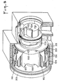
- Figure 3 shows a second version of the shears where the bearing rings are located on the engine side so that the cutting part is cantilevered.
- Figure 4 shows the rotating part of the second version, in exploded perspective.
- Figure 5 shows the second version of the partially cutaway perspective shear.
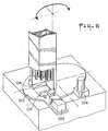
- FIG. 6 shows an example of displacement of the bundle holder magazine (displacement by rotation), in partially cutaway perspective view.
- Example 1 description of a shear according to the invention (first version).
- the shears consist of a frame 1 closed on one side by a door stopper 2 to which the horizontal shaft 3 is fixed. The other end of the frame is closed by a door 4.
- the sleeves 5 and 6 On the shaft 3 are placed the sleeves 5 and 6. On the sleeve 5 rotates a motor 9, for example hydraulic, or a set of motors. The speed of rotation of this (or these) motor (s) is adjustable between 1 and 10 rpm. The total torque must be between 0.5 and 1 MN / m.
- a motor 9 for example hydraulic, or a set of motors.
- the speed of rotation of this (or these) motor (s) is adjustable between 1 and 10 rpm.
- the total torque must be between 0.5 and 1 MN / m.
- a seal is mounted between the rotor 10 and the frame 1.
- the blade holder 12 carrying the stepped teeth 13 and the single tooth 19.
- the stepped teeth are intended to cut the tubes of the bundle while tooth 19 only cuts the foot of the bundle.
- the ring 14 is mounted on the sheath 6.
- The-ring 14 has a notch 15 in which engages the foot of the bundle for cutting said foot. Lateral grooves 16 make it possible to place a gauge 17 in the notch.
- the surface of the gauge 17 is machined cylindrical coaxial with the whole of the rotor. The t61e of this gauge will be described in the example of operation of the shears.
- the upper part of the frame has an opening where the presser 22 is fixed.
- said presser can be moved by translation along the arrow A.
- a magazine 21 is fixed containing the bundle of tubes 20 to be sheared.
- the frame includes a part 23 forming a counter blade during shearing.
- a gas such as air or nitrogen is blown through the pipe 25.
- a seal 26 is interposed, between the door 2 and the frame 1, a seal 29, between the frame 1 and the blade holder 12, a seal 31 .
- the purpose of a device not shown is to press on the upper end of the bundle of tubes to ensure the descent after each cut.
- the presser 22 is brought into an upright position, that is to say above the notch 15.
- a caliber 17 of suitable thickness is chosen for the upper part of the blade 19 to be at the same height as the top of the beam foot when the foot touches the caliber 17
- a half-turn of the engine is made so that the blade 19 shears the foot, then another half-turn to drive the cut part until the discharge 27.
- the assembly 20, 21, 22 is then moved to the left position, that is to say above the teeth 13 and the motor is made to rotate in a continuous movement at a speed of between 1 and 10 rpm.
- the teeth 13 are offset, which has the effect of making the cutting of the progressive bundle of tubes. Unlike a single straight tooth which would cut across its entire width, the system described was chosen after testing.
- the circumferential length of the teeth is such that a set of teeth attacks only when the immediately preceding set has finished cutting the bundle: the developed length of each tooth is at least equal to the total width of the bundle of tubes.
- the device already indicated lowers the entire beam by a height equal to the height of the teeth and the cutting is resumed by the next set of teeth.
- FIG 2 there is shown a blade holder having two sets of teeth distributed in 6 stages, but these numbers can be changed, in particular according to the dimensions of the tubes constituting the bundles.-or the hardness of the metal of the tubes , among other factors.
- the teeth will be chosen by experience.
- the pieces of sheared tubes accompany the rotor during a half-turn and fall through the outlet 28 for example to a dissolver (not shown).
- outlets 27 and 28 are represented in FIG. 1 with hydraulic guards preventing an external propagation of the contamination or the steam outlets rising from the dissolver.
- Example 2 description of another shears according to the invention (said second version).
- the second version differs from the first by a further separation of the "clean" mechanical part and the "polished” cut part. To do this, cut the part was mounted port ⁇ . up to away from the bearings.
- Figure 3 shows this second version in section. There are almost the same parts as on the previous version.
- a frame 101 is closed at one end by a door stopper 103 to which a non-rotating shaft 105 is fixed.
- the frame has a bore on which the sleeve 104 is fitted. Inside said sleeve are housed two bearing rings 106.
- the rotating part consists of the motor 107 identical to that described in the first embodiment according to the invention, and of the rotor 102.
- the rear part of said rotor turns inside the bearing rings 106 in such a way that the part cuts turns overhang.
- the seal between the rear part and the cut part is ensured by a seal 109.
- the section part is also simplified compared to the first version described above, in the sense that the ring 14 of FIG. 1 of the first version is no longer distinct from the rotor: the part 120 (front part of the rotor of FIG. 3) groups parts 10 and 14 of FIG. 1 of the first version, so that the notch 125 is machined in part 120.
- FIG. 3 Also shown in FIG. 3 is the supply part which, in this figure, has the same configuration as in the first version. It is therefore unnecessary to describe it a second time.
- the machine is isolated by hydraulic guards 135.
- the front door 130 has a seal 131 to prevent dust from escaping towards the atmosphere of the work cell 132, the left door carries the seal 141, and between the blade holder and the frame seal 142 is placed.
- this second embodiment of the invention is identical to that of the first version, as regards both the cutting of the base and the cutting of the tubes of the bundle. Obviously, the direction of rotation of the cutting elements must be adapted to the shape of the teeth.
- FIG. 6 shows in perspective a second embodiment of this movement: the presser 201 and the magazine holder are mounted on a rotating plate 202.
- a jack 203 has also been shown actuating the presser and the counter blade 210. This part of the mechanism is not shown in Figures 1 and 3 to lighten the drawing.
- the direction of rotation of the cutting element may be reversed, if necessary (this will depend on the arrangement of the teeth) between the cutting of the foot and that of the tubes.
- the axis of the shears can be horizontal or vertical.
- the claimed device is capable of a plurality of practical embodiments and is not limited to the examples described.
Landscapes
- Physics & Mathematics (AREA)
- Engineering & Computer Science (AREA)
- Plasma & Fusion (AREA)
- General Engineering & Computer Science (AREA)
- High Energy & Nuclear Physics (AREA)
- Shearing Machines (AREA)
- Disintegrating Or Milling (AREA)
- Sawing (AREA)
- Crushing And Pulverization Processes (AREA)
- Processing Of Solid Wastes (AREA)
Applications Claiming Priority (2)
| Application Number | Priority Date | Filing Date | Title |
|---|---|---|---|
| FR8105880 | 1981-03-24 | ||
| FR8105880A FR2502830A1 (fr) | 1981-03-24 | 1981-03-24 | Dispositif rotatif permettant de cisailler un faisceau de tubes contenant des combustibles nucleaires |
Publications (2)
| Publication Number | Publication Date |
|---|---|
| EP0061396A1 true EP0061396A1 (de) | 1982-09-29 |
| EP0061396B1 EP0061396B1 (de) | 1984-09-26 |
Family
ID=9256585
Family Applications (1)
| Application Number | Title | Priority Date | Filing Date |
|---|---|---|---|
| EP82400491A Expired EP0061396B1 (de) | 1981-03-24 | 1982-03-18 | Drehbare Vorrichtung zum Durchtrennen eines verbrannten Kernbrennstoff enthaltenden Rohrbündels |
Country Status (6)
| Country | Link |
|---|---|
| US (1) | US4510832A (de) |
| EP (1) | EP0061396B1 (de) |
| JP (1) | JPS58113796A (de) |
| CA (1) | CA1174962A (de) |
| DE (1) | DE3260815D1 (de) |
| FR (1) | FR2502830A1 (de) |
Cited By (5)
| Publication number | Priority date | Publication date | Assignee | Title |
|---|---|---|---|---|
| FR2534732A1 (fr) * | 1982-10-13 | 1984-04-20 | Cerca | Procede et dispositif pour le demantelement de grappes de barres irradiees |
| FR2611077A1 (fr) * | 1987-02-17 | 1988-08-19 | Sgn Soc Gen Tech Nouvelle | Procede et dispositif pour couper des elements combustibles irradies en position horizontale a l'aide d'un chariot porte-lame |
| DE3734038C1 (en) * | 1987-10-08 | 1989-03-02 | Kernforschungsz Karlsruhe | Remote-controlled shears for cutting up irradiated nuclear fuel rods into segments |
| EP0347312A1 (de) * | 1988-06-15 | 1989-12-20 | SOCIETE GENERALE POUR LES TECHNIQUES NOUVELLES S.G.N. Société anonyme dite: | Vorrichtung zum Schneiden eines Stabbündels |
| FR2633089A1 (fr) * | 1988-06-20 | 1989-12-22 | Sgn Soc Gen Tech Nouvelle | Procede et dispositif de coupe d'un faisceau de tubes irradies, contenant du combustible nucleaire |
Families Citing this family (3)
| Publication number | Priority date | Publication date | Assignee | Title |
|---|---|---|---|---|
| DE3301814C2 (de) * | 1983-01-20 | 1986-11-20 | Kraftwerk Union AG, 4330 Mülheim | Vorrichtung zum Beseitigen von länglichen Kerninstrumentierungssonden aus Kernreaktoren |
| DE3525504A1 (de) * | 1985-07-17 | 1987-01-29 | Thyssen Industrie | Brennelement-buendelschere mit schneidstaubableitung |
| RU2658295C1 (ru) * | 2017-08-24 | 2018-06-20 | Федеральное Государственное Унитарное Предприятие "Горно - Химический Комбинат" (Фгуп "Гхк") | Способ расчехловки тепловыделяющих элементов и устройство для его осуществления |
Citations (5)
| Publication number | Priority date | Publication date | Assignee | Title |
|---|---|---|---|---|
| FR1379741A (fr) * | 1963-10-16 | 1964-11-27 | Electricite De France | Procédé de déchemisage et appareil faisant application dudit procédé ou d'un procédé analogue |
| FR2186711A1 (de) * | 1972-05-31 | 1974-01-11 | Westinghouse Electric Corp | |
| FR2242751A1 (de) * | 1973-09-05 | 1975-03-28 | Kernforschungsanlage Juelich | |
| FR2257983A1 (en) * | 1974-01-11 | 1975-08-08 | Saint Gobain Techn Nouvelles | Spent fuel rod sectioning apparatus - for recovery of fissionable or fertile nuclear fuel |
| FR2324093A1 (fr) * | 1975-09-11 | 1977-04-08 | Saint Gobain Techn Nouvelles | Procede et dispositif pour alimenter une tronconneuse de combustible nucleaire |
Family Cites Families (4)
| Publication number | Priority date | Publication date | Assignee | Title |
|---|---|---|---|---|
| NL291174A (de) * | 1962-04-12 | |||
| US3621742A (en) * | 1968-03-25 | 1971-11-23 | Gen Electric | Irradiated fuel processing system |
| US3722338A (en) * | 1970-02-25 | 1973-03-27 | Saint Gobain Tech Nouvellas | Apparatus and process for the treatment of spent fuel |
| FR2324094A1 (fr) * | 1975-09-11 | 1977-04-08 | Saint Gobain Techn Nouvelles | Procede et dispositif pour cisailler un faisceau de tubes contenant des combustibles nucleaires |
-
1981
- 1981-03-24 FR FR8105880A patent/FR2502830A1/fr active Pending
-
1982
- 1982-03-18 EP EP82400491A patent/EP0061396B1/de not_active Expired
- 1982-03-18 DE DE8282400491T patent/DE3260815D1/de not_active Expired
- 1982-03-24 US US06/361,285 patent/US4510832A/en not_active Expired - Fee Related
- 1982-03-24 JP JP57045734A patent/JPS58113796A/ja active Granted
- 1982-03-24 CA CA000399314A patent/CA1174962A/en not_active Expired
Patent Citations (5)
| Publication number | Priority date | Publication date | Assignee | Title |
|---|---|---|---|---|
| FR1379741A (fr) * | 1963-10-16 | 1964-11-27 | Electricite De France | Procédé de déchemisage et appareil faisant application dudit procédé ou d'un procédé analogue |
| FR2186711A1 (de) * | 1972-05-31 | 1974-01-11 | Westinghouse Electric Corp | |
| FR2242751A1 (de) * | 1973-09-05 | 1975-03-28 | Kernforschungsanlage Juelich | |
| FR2257983A1 (en) * | 1974-01-11 | 1975-08-08 | Saint Gobain Techn Nouvelles | Spent fuel rod sectioning apparatus - for recovery of fissionable or fertile nuclear fuel |
| FR2324093A1 (fr) * | 1975-09-11 | 1977-04-08 | Saint Gobain Techn Nouvelles | Procede et dispositif pour alimenter une tronconneuse de combustible nucleaire |
Cited By (7)
| Publication number | Priority date | Publication date | Assignee | Title |
|---|---|---|---|---|
| FR2534732A1 (fr) * | 1982-10-13 | 1984-04-20 | Cerca | Procede et dispositif pour le demantelement de grappes de barres irradiees |
| FR2611077A1 (fr) * | 1987-02-17 | 1988-08-19 | Sgn Soc Gen Tech Nouvelle | Procede et dispositif pour couper des elements combustibles irradies en position horizontale a l'aide d'un chariot porte-lame |
| EP0279741A1 (de) * | 1987-02-17 | 1988-08-24 | SOCIETE GENERALE POUR LES TECHNIQUES NOUVELLES S.G.N. Société anonyme dite: | Verfahren und Vorrichtung zum Schneiden von verstrahlten Brennelementen in horizontaler Richtung unter Verwendung eines Messerschlittens |
| DE3734038C1 (en) * | 1987-10-08 | 1989-03-02 | Kernforschungsz Karlsruhe | Remote-controlled shears for cutting up irradiated nuclear fuel rods into segments |
| EP0347312A1 (de) * | 1988-06-15 | 1989-12-20 | SOCIETE GENERALE POUR LES TECHNIQUES NOUVELLES S.G.N. Société anonyme dite: | Vorrichtung zum Schneiden eines Stabbündels |
| FR2633088A1 (fr) * | 1988-06-15 | 1989-12-22 | Sgn Soc Gen Tech Nouvelle | Dispositif pour cisailler un assemblage de tubes |
| FR2633089A1 (fr) * | 1988-06-20 | 1989-12-22 | Sgn Soc Gen Tech Nouvelle | Procede et dispositif de coupe d'un faisceau de tubes irradies, contenant du combustible nucleaire |
Also Published As
| Publication number | Publication date |
|---|---|
| FR2502830A1 (fr) | 1982-10-01 |
| JPS58113796A (ja) | 1983-07-06 |
| EP0061396B1 (de) | 1984-09-26 |
| US4510832A (en) | 1985-04-16 |
| JPH0229198B2 (de) | 1990-06-28 |
| DE3260815D1 (en) | 1984-10-31 |
| CA1174962A (en) | 1984-09-25 |
Similar Documents
| Publication | Publication Date | Title |
|---|---|---|
| EP0061396B1 (de) | Drehbare Vorrichtung zum Durchtrennen eines verbrannten Kernbrennstoff enthaltenden Rohrbündels | |
| EP2504102B1 (de) | Gehäuse für dichte verbindungsvorrichtung und aseptische transfervorrichtung | |
| EP2647462B1 (de) | Elektrodenwechsler mit translatorischem Antrieb von Greiffern | |
| FR2561151A1 (fr) | Procede et installation de soudage de grilles pour assemblage de combustible nucleaire | |
| WO2009087297A1 (fr) | Machine a cintrer un profile selon deux sens de cintrage et outillage de cintrage | |
| EP0219404A1 (de) | Innenbearbeitungsvorrichtung für eine Röhre | |
| CA1211029A (fr) | Machine a scie annulaire pour le tronconnage de tubes | |
| EP0524121A1 (de) | Einrichtung zum Entmanteln der mit einem isolierendem oder schutzendem Schicht überzogener Leiteroberfläche | |
| EP0388296A1 (de) | Interventionsvorrichtung, insbesondere zur Prüfung, Inspektion und Wartung von Wärmeaustauschern | |
| EP0074888B1 (de) | Einrichtung zur Manipulation einer Last sowie Anwendung bei der Manipulation einer eingetauchten Last | |
| FR2610508A1 (fr) | Appareil a biopsie osseuse | |
| EP0682222A1 (de) | Automatische Ladevorrichtung für einen Ofen im Weltraum | |
| EP0374334B1 (de) | Hydraulische Schneidvorrichtung | |
| EP0600786B1 (de) | Automatische Ladevorrichtung für einen Ofen im Weltraum | |
| EP0320357B1 (de) | Maschine zum Entfernen des Abstandsdrahtes von Kernbrennstäben | |
| EP0311522A1 (de) | Vorrichtung zum Halten von zwei zusammenzubauenden Strukturelementen | |
| EP4223405A1 (de) | Vorrichtung zum einsetzen eines packungsabschnitts | |
| FR2520593A1 (fr) | Dispositif de coupe pour tiges continues de cigarettes | |
| WO2004035251A2 (fr) | Procede et dispositif pour l'extraction et/ou le changement des electrodes d'une pince a souder ou d'un appareil de soudage | |
| EP4223406B1 (de) | Vorrichtung zum einsetzen eines packungsabschnitts | |
| EP0072765A1 (de) | Vorrichtung zum Werkzeugwechseln an Pilgerschrittwalzwerken | |
| EP0639775B1 (de) | Vorrichtung zur Lagerung von zylindrischen Gegenständen, mit schneller Be- und Entladung | |
| FR3118270A1 (fr) | Installation de nettoyage d’un assemblage combustible et procédé de nettoyage qui en fait usage | |
| FR2524367A1 (fr) | Dispositif telemanipulaire pour le decoupage de toles et de tubes en atmosphere dangereuse | |
| EP0760257B1 (de) | Schervorrichtung für verschiedenartige Körper |
Legal Events
| Date | Code | Title | Description |
|---|---|---|---|
| PUAI | Public reference made under article 153(3) epc to a published international application that has entered the european phase |
Free format text: ORIGINAL CODE: 0009012 |
|
| AK | Designated contracting states |
Designated state(s): BE CH DE FR GB IT LI SE |
|
| 17P | Request for examination filed |
Effective date: 19821231 |
|
| ITF | It: translation for a ep patent filed | ||
| GRAA | (expected) grant |
Free format text: ORIGINAL CODE: 0009210 |
|
| AK | Designated contracting states |
Designated state(s): BE CH DE FR GB IT LI SE |
|
| REF | Corresponds to: |
Ref document number: 3260815 Country of ref document: DE Date of ref document: 19841031 |
|
| PLBE | No opposition filed within time limit |
Free format text: ORIGINAL CODE: 0009261 |
|
| STAA | Information on the status of an ep patent application or granted ep patent |
Free format text: STATUS: NO OPPOSITION FILED WITHIN TIME LIMIT |
|
| 26N | No opposition filed | ||
| PGFP | Annual fee paid to national office [announced via postgrant information from national office to epo] |
Ref country code: CH Payment date: 19920311 Year of fee payment: 11 |
|
| PGFP | Annual fee paid to national office [announced via postgrant information from national office to epo] |
Ref country code: SE Payment date: 19920326 Year of fee payment: 11 |
|
| ITTA | It: last paid annual fee | ||
| PGFP | Annual fee paid to national office [announced via postgrant information from national office to epo] |
Ref country code: BE Payment date: 19920409 Year of fee payment: 11 |
|
| PG25 | Lapsed in a contracting state [announced via postgrant information from national office to epo] |
Ref country code: SE Effective date: 19930319 |
|
| PG25 | Lapsed in a contracting state [announced via postgrant information from national office to epo] |
Ref country code: LI Effective date: 19930331 Ref country code: CH Effective date: 19930331 Ref country code: BE Effective date: 19930331 |
|
| BERE | Be: lapsed |
Owner name: SOC. GENERALE POUR LES TECHNIQUES NOUVELLES SGN Effective date: 19930331 |
|
| REG | Reference to a national code |
Ref country code: CH Ref legal event code: PL |
|
| EUG | Se: european patent has lapsed |
Ref document number: 82400491.5 Effective date: 19931008 |
|
| PGFP | Annual fee paid to national office [announced via postgrant information from national office to epo] |
Ref country code: GB Payment date: 19950310 Year of fee payment: 14 |
|
| PGFP | Annual fee paid to national office [announced via postgrant information from national office to epo] |
Ref country code: DE Payment date: 19950324 Year of fee payment: 14 |
|
| PGFP | Annual fee paid to national office [announced via postgrant information from national office to epo] |
Ref country code: FR Payment date: 19951228 Year of fee payment: 15 |
|
| PG25 | Lapsed in a contracting state [announced via postgrant information from national office to epo] |
Ref country code: GB Effective date: 19960318 |
|
| GBPC | Gb: european patent ceased through non-payment of renewal fee |
Effective date: 19960318 |
|
| PG25 | Lapsed in a contracting state [announced via postgrant information from national office to epo] |
Ref country code: DE Effective date: 19961203 |
|
| PG25 | Lapsed in a contracting state [announced via postgrant information from national office to epo] |
Ref country code: FR Free format text: LAPSE BECAUSE OF NON-PAYMENT OF DUE FEES Effective date: 19971128 |
|
| REG | Reference to a national code |
Ref country code: FR Ref legal event code: ST |