EP0061398A1 - Verfahren und Vorrichtung zum Speichern und Ausklinken von zylindrischen Objekten in Fahrzeugen - Google Patents
Verfahren und Vorrichtung zum Speichern und Ausklinken von zylindrischen Objekten in Fahrzeugen Download PDFInfo
- Publication number
- EP0061398A1 EP0061398A1 EP82400496A EP82400496A EP0061398A1 EP 0061398 A1 EP0061398 A1 EP 0061398A1 EP 82400496 A EP82400496 A EP 82400496A EP 82400496 A EP82400496 A EP 82400496A EP 0061398 A1 EP0061398 A1 EP 0061398A1
- Authority
- EP
- European Patent Office
- Prior art keywords
- plug
- bladder
- tube
- container
- ejectable
- Prior art date
- Legal status (The legal status is an assumption and is not a legal conclusion. Google has not performed a legal analysis and makes no representation as to the accuracy of the status listed.)
- Granted
Links
- 238000000034 method Methods 0.000 title claims abstract description 5
- 230000007774 longterm Effects 0.000 claims description 4
- 230000001143 conditioned effect Effects 0.000 claims description 2
- 238000009527 percussion Methods 0.000 claims description 2
- 230000008901 benefit Effects 0.000 description 5
- 230000000295 complement effect Effects 0.000 description 3
- 239000003814 drug Substances 0.000 description 2
- 230000009467 reduction Effects 0.000 description 2
- 239000000779 smoke Substances 0.000 description 2
- 230000009471 action Effects 0.000 description 1
- 230000000903 blocking effect Effects 0.000 description 1
- 230000008878 coupling Effects 0.000 description 1
- 238000010168 coupling process Methods 0.000 description 1
- 238000005859 coupling reaction Methods 0.000 description 1
- 229940079593 drug Drugs 0.000 description 1
- 239000000428 dust Substances 0.000 description 1
- 230000000694 effects Effects 0.000 description 1
- 229920001971 elastomer Polymers 0.000 description 1
- 239000000806 elastomer Substances 0.000 description 1
- 239000013536 elastomeric material Substances 0.000 description 1
- 230000005484 gravity Effects 0.000 description 1
- 238000005259 measurement Methods 0.000 description 1
- 230000004048 modification Effects 0.000 description 1
- 238000012986 modification Methods 0.000 description 1
- 238000004806 packaging method and process Methods 0.000 description 1
- 238000002360 preparation method Methods 0.000 description 1
- 230000008569 process Effects 0.000 description 1
- 238000007789 sealing Methods 0.000 description 1
- 230000035939 shock Effects 0.000 description 1
- 230000008961 swelling Effects 0.000 description 1
- 229920003051 synthetic elastomer Polymers 0.000 description 1
- 230000008719 thickening Effects 0.000 description 1
- 230000001960 triggered effect Effects 0.000 description 1
Images


Classifications
-
- B—PERFORMING OPERATIONS; TRANSPORTING
- B64—AIRCRAFT; AVIATION; COSMONAUTICS
- B64D—EQUIPMENT FOR FITTING IN OR TO AIRCRAFT; FLIGHT SUITS; PARACHUTES; ARRANGEMENT OR MOUNTING OF POWER PLANTS OR PROPULSION TRANSMISSIONS IN AIRCRAFT
- B64D1/00—Dropping, ejecting, releasing or receiving articles, liquids, or the like, in flight
- B64D1/02—Dropping, ejecting, or releasing articles
-
- B—PERFORMING OPERATIONS; TRANSPORTING
- B63—SHIPS OR OTHER WATERBORNE VESSELS; RELATED EQUIPMENT
- B63B—SHIPS OR OTHER WATERBORNE VESSELS; EQUIPMENT FOR SHIPPING
- B63B22/00—Buoys
- B63B22/003—Buoys adapted for being launched from an aircraft or water vehicle;, e.g. with brakes deployed in the water
-
- B—PERFORMING OPERATIONS; TRANSPORTING
- B63—SHIPS OR OTHER WATERBORNE VESSELS; RELATED EQUIPMENT
- B63C—LAUNCHING, HAULING-OUT, OR DRY-DOCKING OF VESSELS; LIFE-SAVING IN WATER; EQUIPMENT FOR DWELLING OR WORKING UNDER WATER; MEANS FOR SALVAGING OR SEARCHING FOR UNDERWATER OBJECTS
- B63C9/00—Life-saving in water
- B63C9/22—Devices for holding or launching life-buoys, inflatable life-rafts, or other floatable life-saving equipment
-
- F—MECHANICAL ENGINEERING; LIGHTING; HEATING; WEAPONS; BLASTING
- F41—WEAPONS
- F41F—APPARATUS FOR LAUNCHING PROJECTILES OR MISSILES FROM BARRELS, e.g. CANNONS; LAUNCHERS FOR ROCKETS OR TORPEDOES; HARPOON GUNS
- F41F5/00—Launching-apparatus for gravity-propelled missiles or projectiles
Definitions
- the present invention relates to a method and devices intended for the storage and then the dropping of a cylindrical object, for example in the dropping at sea of a cylindrical buoy, from an aircraft or a boat.
- aircraft which are equipped with launching tubes in each of which a cylindrical object is placed before takeoff ' from the aircraft which must be dropped in flight.
- the objects must be dropped either several at the same time, in well-determined places, or in a staggered manner and the launching tubes include means which allow the crew to prepare the release and to order it at the desired moment.
- the objective of the present invention is to provide means which make it possible to condition objects to be dropped for long-term storage and which make it possible to use the storage containers to drop the object which they contain, with speed. of launch determined in intensity and direction.
- the device for locking the ejectable cap is of the type comprising two connecting rods hinged together and at their ends, which form a toggle joint having a locking position and the release vehicle comprises a striker which makes it possible to unlock, by percussion. , said toggle joint, which causes the unlocking of said front plug and the ejection of said plug and said object under the pressure of the compressed air contained in the bladder.
- the invention results in new containers which can be used both for packaging the releasable buoys, or any other similar releasable cylindrical object, during storage which can be of long duration and for dropping them, from an aircraft, a helicopter or a boat with a speed that can be determined by choosing the inflation pressure of the inflatable bladder.
- an inflatable bladder has many advantages. It allows the use during storage of a low inflation pressure which is intended only to maintain the cohesion of the assembly placed inside the container and to inflate the bladder to the pressure desired for the release during preparations for the latter. before loading the containers in the drop vehicle ...
- an inflatable bladder avoids the risks of friction or lack of tightness which could occur with containers fitted with a piston and a chamber filled with compressed air and, therefore, a container equipped with an inflatable bladder allows to obtain at the time of the release a good reproducibility of the ballistic characteristics.
- the containers according to the invention which are fitted with a rear plug carrying a fixing device which cooperates with a complementary device carried by the release vehicle allow the containers according to the invention to be used as launching tubes. It is also possible to place the containers according to the invention in the gravity launch tubes which equip certain drop vehicles. j
- La.figure 1 is an axial section of a container according to the invention.
- Figure 2 is an axial section of a cascade arrangement of two containers according to the invention.
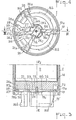
- the figures 3 and 4 are respectively an axial section and a front view of a first embodiment of a device for locking the ejectable plug.
- Figures 5, 6 and 7 are respectively a view in ' axial section, in cross section and a partial perspective view of a second embodiment of a device for locking the ejectable plug.
- Figure 8 is an axial section of the rear end of a container according to the invention.
- FIG. 1 represents an axial section of a cylindrical container 1, of axis x xl, in which is placed a cylindrical object 2 which is to be released from an aircraft from which a part of the fuselage 3 which has been depicted, has an orifice drop 4 opposite which the container 1 is placed.
- the inclination of the axis x xl relative to the aircraft is determined so that the object to be dropped leaves the aircraft with a determined direction trajectory in order to avoid that it risks striking the aircraft.
- a dropping aircraft has a plurality of dropping orifices 4 opposite each of which can be placed a container 1 according to the invention.
- Each of the release orifices 4 is equipped with a device for guiding the container 1, which consists for example of a sleeve 4a.
- cylindrical is used in a general sense to designate any volume delimited by parallel generatrices and it includes cylinders whose cross section is not circular.
- the objects to be dropped 2 are for example listening or measuring buoys which must be dropped at sea, or containers containing relief items such as food, medication or inflatable boat, light or smoke markers or acoustic beacons or radio-electric etc ...
- the container 1 comprises a cylindrical tube 5 whose diameter or section are slightly greater than those of the object 2, so that the latter can slide freely inside the container.
- the tube 5 has a length greater than that of the object 2, for example a length of the order of 1.5 times the length of the object 2.
- the tube 5 is open at its two axial ends.
- the rear end is closed by a plug 6 which is fixed to the tube for example by screwing or by any other equivalent means.
- the front end is closed by a plug 7 which is an ejectable plug comprising a locking device 8 which is unlocked at the time of launch by a striker 9 fixed to the aircraft.
- the striker 9 is actuated for example by a spring 10 or by an electromagnet, or by any other equivalent means.
- the tube 5 contains an inflatable bladder or envelope 11, which is located in contact with the rear plug, and a distribution disc 12 which is interposed between the bladder 11 and the rear end of the object to be dropped.
- the disc 12 is a disc made of an elastomeric material, for example of relatively hard artificial rubber. Its function is to protect the inflatable bladder 11 from direct contact with the rear face of the object 2 which may have roughness.
- the casing 11 includes a valve 13 which passes through the rear plug 6.
- a container according to the invention is as follows. At first, the disc 12 is successively placed in the container, then the rear plug 6 carrying the bladder 11 and the valve 12, then the object to be released 2 and finally the plug 7 which is locked.
- the bladder 11 is slightly inflated so that it maintains the object 2 applied against the front cap. It is thus possible to provide long-term storage of the objects to be dropped 2 placed inside the container which effectively protects them from dust and shocks.
- the bladders 11 are inflated by means of the valves 13 under a pressure which is between 2 bars and 10 bars depending on the desired ejection speed, which depends on the speed of the aircraft or boat drop.
- the bladders 11 are composed of a thin elastomer envelope which can undergo without increasing a tear an increase in volume of the order of five to seven times.
- the crew of the aircraft sets off the strikers 9 which strike the locking devices 8 and which cause the release of the plug 7.
- the plug 7 and the load 2 are ejected under the thrust. compressed air contained in the bladder 11. Thanks to its great deformability; the bladder 11 can occupy, without tearing, the entire interior volume of the container 5, so that it pushes the load 2 during all of its progression inside the tube 5.
- the wall of the tube 5 preferably has a small internal shoulder 14 which allows the load 2 to pass, but which stops the disc 12 and the bladder 11, so that these can be recovered at the same time as the container.
- the shoulder 14 is situated slightly set back from the front end of the load 2 in order to avoid that it risks catching the latter.
- FIG. 1 represents an example of the use of a container according to the invention used as a launching tube.
- the rear plug 6 has slots 15 forming the male part of a bayonet coupling or the like which cooperate with complementary slots 16, forming the female part of a support 17 which is fixed to the launcher and which allows. to orient the x xl axis of the container in a well-defined position with respect to. launcher to obtain a determined direction of launch speed.
- the support 17 is fixed to the launcher opposite a launch orifice.
- the containers 1 according to the invention can be placed in these tubes.
- the front plug 7 may also include, on its outer face, a female assembly end piece identical to the end piece 16 and, in this case, it is possible to mount several containers in cascade, one behind the other, and to drop them one after the other.
- FIG. 2 shows an example of such a cascade arrangement of two coaxial containers making it possible to drop two cylindrical loads 2a and 2b successively through the same release orifice 4 which is equipped in this example with guide rails 4b, 4c.
- the container 1b is fixed, as in the case of FIG. 1, on a support 1-7, comprising assembly slots 16, which is fixed to the structure 18 of the launcher.
- the front plug 7b of the container 1b has assembly slots 16b identical to the slots 16, so that a second container comprising it a rear plug 6a identical to the plug 6b can be assembled coaxially on the slots and so on.
- the dropping vehicle must include several strikers 9a, 9b staggered along the containers to control the successive drops.
- Such a cascade arrangement has the advantage of making it possible to drop successively, by the same release orifice, several charges. It makes it possible to increase the launching capacity of the same vehicle and to fully benefit from the reduction in length of the charges 2 which is made possible by the increasingly extensive miniaturization of the components thereof, in particular electronic components.
- Figure 3 is an axial section on a larger scale of the front end of a container according to the invention.
- Figure 4 is a bottom view of Figure 3.
- FIGS. 3 and 4 represent the front end of a container 1. which is equipped with an ejectable plug 7b making it possible to fix a second container in cascade on this plug, as shown in FIG. 2.
- the plug 7b shown in FIGS. 3 and 4 has outward extensions 16b which form male studs in the form of slots which are intended to cooperate with the studs 17 of the rear plug of another container.
- the arrangement of the pins of this bayonet assembly is such that the two containers can only be assembled in one position so that the triggers on the locking devices are aligned.
- Figures 3 and 4 show a first embodiment of a device for locking the ejectable plug.
- This device comprises several levers, for example three levers 19, 20 and 21 arranged at 120 ° from one another. Each lever is articulated around an axis, respectively 19a, 20a and 21a, located near the periphery.
- each lever located towards the exterior, is engaged in a slot 22 cut out in the wall of the container 1.
- a notch 19b, 20b and 21b In the locked position, the end of the large arm of each lever is engaged in a notch 19b, 20b and 21b respectively.
- the three notches 19b, 20b and 21b are cut radially in a central boss 23 which extends outwards the body of the plug. Outside this boss 23 is located a rotary disc 24. which can pivot around a central axis 25. This disc also carries three notches 24a, 24b and 24c which are superimposed on the notches 19b, 20b and 21b when the device is unlocked.
- the disc 24 is integral with an arm 26, the free end of which is articulated at 26a on a toggle or compass blocking system which comprises two movable links 27 and 28.
- the link 28 is articulated at 28a on the plug and in 27a on the intermediate link 27 which is itself articulated at 26a on the arm 26.
- the operation is as follows.
- the disc 24 and the arm 26 cannot pivot in the direction which would release the levers, because the toggle joint is blocked.
- the link 27 occupies position 27 ′ which touches the wall of the container.
- each lever 19, 20 and 21 carries, at the end of the large arm, an inclined range 19c, 20c, 21c forming a ramp which tends to rotate the disc 24 under the action of the bladder push, in the direction closing the compass formed by the parts 27 and 28; which places the notches 24a, 24b and 24c above the notches 19b, 20b and 21b and releases the levers 19, 20 and 21.
- FIGS. 5 and 6 show, in axial and cross section, another embodiment of a front cap 7. ejectable.
- a plug is not shown in these figures equipped with a bayonet assembly device .16b as in the case of FIGS. 3 and 4, but of course, the plug according to FIGS. 5 and 6 could be fitted with such a device.
- the plug 7 is locked by a rod or an elastic ring 30 which is placed in a groove 31 hollowed out at the internal periphery of the front end of the tube 5 and in a groove 32 hollowed out at the periphery of the plug 7.
- the groove 32 has a depth greater than the diameter of the rod 30, so that the latter can be entirely housed in the groove 32.
- the rod 30 is prestressed, so that it tends to under the effect of elastic forces, to close and re-enter the groove 32.
- the rod 30 is open and its two ends are connected to each other by a locking device 33 of the toggle or compass type.
- the groove 31 has an inclined external franc 31a which facilitates the closing of the elastic ring 30.
- Figures 5 and 6 show the device 33 in the locked position, in which the rod 30 is kept open and partially engaged in the groove 31, so that the plug 7 can not be ejected.
- the locking device comprises an intermediate piece 34 which is flush with the external wall of the container, in the locked position, through a window 35 of said wall.
- the striker 9 strikes' on the part 34 in the direction of the arrow P, which causes the release of the toggle joint device which is housed in a housing 36, formed in the plug 7.
- FIG. 7 shows a perspective view of the locking device of Figures 5 and 6.
- the end 30a is articulated around an axis 34a on a rod 34 in form of yoke or stirrup.
- the end 30b is articulated around an axis 37a on a second intermediate link 37 which is. itself articulated around an axis 38 on the part 34.
- the two links 34, 37 form a compass whose joint 38 is the top. If the joint 38 is placed outside the alignment defined by the axes 36a and 37a, the elastic forces exerted by the rod 30 cannot close this compass which remains blocked until the striker has repelled part 34 inwards.
- the rod 30 is housed inside the groove 32 of the plug and it is .. ejected at the same time as the plug.
- FIG. 8 represents an axial section on a larger scale of the rear end of the container 1.
- This section shows the fixed plug 6, which is a threaded plug and the bladder 11 which includes an inflation valve 13 which passes through the plug and which is provided with a valve 13a.
- FIG. 8 also shows a pressure sensor device which is composed of a rod 40 which passes through the plug and which bears against a spring leaf 41 fixed to the internal face of the plug. When the bladder 11 is normally inflated, it crushes the spring 41 and the rod 40 protrudes outside the plug where it actuates a contact indicating normal swelling.
- the rod 40 opens the contact which activates an alarm or a prohibition of dropping.
Landscapes
- Engineering & Computer Science (AREA)
- Aviation & Aerospace Engineering (AREA)
- Mechanical Engineering (AREA)
- Ocean & Marine Engineering (AREA)
- Chemical & Material Sciences (AREA)
- Combustion & Propulsion (AREA)
- General Engineering & Computer Science (AREA)
- Filling Or Discharging Of Gas Storage Vessels (AREA)
- Closures For Containers (AREA)
- Replacement Of Web Rolls (AREA)
Applications Claiming Priority (2)
| Application Number | Priority Date | Filing Date | Title |
|---|---|---|---|
| FR8105804A FR2502576A1 (fr) | 1981-03-24 | 1981-03-24 | Procede et dispositifs pour stocker et larguer un objet cylindrique a partir d'un vehicule |
| FR8105804 | 1981-03-24 |
Publications (2)
| Publication Number | Publication Date |
|---|---|
| EP0061398A1 true EP0061398A1 (de) | 1982-09-29 |
| EP0061398B1 EP0061398B1 (de) | 1986-07-23 |
Family
ID=9256551
Family Applications (1)
| Application Number | Title | Priority Date | Filing Date |
|---|---|---|---|
| EP82400496A Expired EP0061398B1 (de) | 1981-03-24 | 1982-03-18 | Verfahren und Vorrichtung zum Speichern und Ausklinken von zylindrischen Objekten in Fahrzeugen |
Country Status (8)
| Country | Link |
|---|---|
| US (1) | US4474101A (de) |
| EP (1) | EP0061398B1 (de) |
| JP (1) | JPS5830897A (de) |
| AU (1) | AU547256B2 (de) |
| BR (1) | BR8201627A (de) |
| CA (1) | CA1187346A (de) |
| DE (1) | DE3272075D1 (de) |
| FR (1) | FR2502576A1 (de) |
Cited By (6)
| Publication number | Priority date | Publication date | Assignee | Title |
|---|---|---|---|---|
| GB2169067A (en) * | 1982-06-16 | 1986-07-02 | Hunting Eng Ltd | Ejection equipment |
| EP0267699A3 (en) * | 1986-11-12 | 1988-08-31 | The Marconi Company Limited | Releasable closure arrangement |
| US4799907A (en) * | 1987-02-03 | 1989-01-24 | Conax Florida Corporation | Survival apparatus |
| GB2320556A (en) * | 1993-02-23 | 1998-06-24 | Marconi Gec Ltd | Gun launchable sensor |
| FR3046779A1 (fr) * | 2016-01-14 | 2017-07-21 | Dassault Aviat | Systeme de largage d'un colis a partir d'un aeronef, aeronef et procede associes |
| FR3046777A1 (fr) * | 2016-01-14 | 2017-07-21 | Dassault Aviat | Trappe d'obturation d'une ouverture menagee a travers la structure d'un aeronef, structure, et procede associes |
Families Citing this family (17)
| Publication number | Priority date | Publication date | Assignee | Title |
|---|---|---|---|---|
| JPS6140331A (ja) * | 1984-07-31 | 1986-02-26 | Sekisui Plastics Co Ltd | 導電性プラスチツクス発泡体の製造法 |
| US5092221A (en) * | 1990-09-28 | 1992-03-03 | The United States Of America As Represented By The Secretary Of The Navy | Launch container for multiple stores |
| US5063823A (en) * | 1990-10-30 | 1991-11-12 | The United States Of America As Represented By The Secretary Of The Navy | Launch container for multiple stores using electrically-actuated paddle assemblies |
| US5076134A (en) * | 1990-10-30 | 1991-12-31 | The United States Of America As Represented By The Secretary Of The Navy | Launch container for multiple stores using piezo electrically-actuated paddle assemblies |
| US5160800A (en) * | 1991-04-24 | 1992-11-03 | The United States Of America As Represented By The Secretary Of The Navy | Obturator retaining means |
| US5279199A (en) * | 1992-08-14 | 1994-01-18 | Hughes Aircraft Company | Technique and apparatus for rearward launch of a missile |
| US5333528A (en) * | 1992-08-28 | 1994-08-02 | Hughes Aircraft Company | Multiple missile ejection system |
| FR2722872B1 (fr) * | 1994-07-19 | 1996-10-04 | Lacroix Soc E | Dispositif pyrotechnique de lancement d'au moins un projectile |
| US6347567B1 (en) * | 2000-05-04 | 2002-02-19 | Donald B. Eckstein | Covert aerial encapsulated munition ejection system |
| FR2817532A1 (fr) * | 2000-12-01 | 2002-06-07 | Jean Jacques Caillon | Perche de reperage a reflecteur radar et lumineux avec lampe stroboscopique |
| FR2817533A1 (fr) * | 2000-12-01 | 2002-06-07 | Jean Jacques Caillon | Perche de securite a largage automatique avec reflecteur radar et lumineux avec lampe stroboscopique pour le reperage et le sauvetage de l'homme a la mer |
| RU2236982C2 (ru) * | 2002-06-20 | 2004-09-27 | Закрытое акционерное общество "Научно-производственный комплекс "Радиосвязь" | Устройство для хранения и сбрасывания спасательного плота |
| US8091481B1 (en) * | 2009-05-01 | 2012-01-10 | Floyd Brian A | Gas strut separation for staged rocket |
| CN106314796A (zh) * | 2016-09-01 | 2017-01-11 | 肇庆高新区异星科技有限公司 | 一种弹射装置 |
| RU2722601C2 (ru) * | 2017-12-18 | 2020-06-02 | Российская Федерация, от имени которой выступает Министерство обороны Российской Федерации | Комплекс спасательный универсальный надводный для подводной лодки |
| FR3155804A1 (fr) * | 2023-11-24 | 2025-05-30 | Aresia-Valenton | Dispositif de vessie à pression de gaz et ensemble d’éjection |
| CN117602072A (zh) * | 2023-12-28 | 2024-02-27 | 中国船舶重工集团公司第七〇五研究所 | 一种直升机内挂空投自航器的投放装置和直升机 |
Citations (3)
| Publication number | Priority date | Publication date | Assignee | Title |
|---|---|---|---|---|
| BE563098A (de) * | ||||
| US3435725A (en) * | 1966-09-01 | 1969-04-01 | Fairchild Hiller Corp | Store launching system |
| FR2413629A1 (fr) * | 1978-01-03 | 1979-07-27 | Raytheon Co | Appareil de lancement de bouees |
Family Cites Families (2)
| Publication number | Priority date | Publication date | Assignee | Title |
|---|---|---|---|---|
| US3387537A (en) * | 1967-02-17 | 1968-06-11 | Navy Usa | Torpedo suspension band |
| DE2462267A1 (de) * | 1974-11-19 | 1977-03-03 | Mak Maschinenbau Gmbh | Ausstossvorrichtung fuer torpedos |
-
1981
- 1981-03-24 FR FR8105804A patent/FR2502576A1/fr active Granted
-
1982
- 1982-03-15 US US06/358,207 patent/US4474101A/en not_active Expired - Fee Related
- 1982-03-18 EP EP82400496A patent/EP0061398B1/de not_active Expired
- 1982-03-18 DE DE8282400496T patent/DE3272075D1/de not_active Expired
- 1982-03-18 AU AU81693/82A patent/AU547256B2/en not_active Ceased
- 1982-03-23 BR BR8201627A patent/BR8201627A/pt unknown
- 1982-03-23 CA CA000399129A patent/CA1187346A/fr not_active Expired
- 1982-03-24 JP JP57045744A patent/JPS5830897A/ja active Pending
Patent Citations (3)
| Publication number | Priority date | Publication date | Assignee | Title |
|---|---|---|---|---|
| BE563098A (de) * | ||||
| US3435725A (en) * | 1966-09-01 | 1969-04-01 | Fairchild Hiller Corp | Store launching system |
| FR2413629A1 (fr) * | 1978-01-03 | 1979-07-27 | Raytheon Co | Appareil de lancement de bouees |
Cited By (9)
| Publication number | Priority date | Publication date | Assignee | Title |
|---|---|---|---|---|
| GB2169067A (en) * | 1982-06-16 | 1986-07-02 | Hunting Eng Ltd | Ejection equipment |
| EP0267699A3 (en) * | 1986-11-12 | 1988-08-31 | The Marconi Company Limited | Releasable closure arrangement |
| US4799907A (en) * | 1987-02-03 | 1989-01-24 | Conax Florida Corporation | Survival apparatus |
| GB2320556A (en) * | 1993-02-23 | 1998-06-24 | Marconi Gec Ltd | Gun launchable sensor |
| GB2320556B (en) * | 1993-02-23 | 1998-09-23 | Marconi Gec Ltd | Gun launchable sensor |
| FR3046779A1 (fr) * | 2016-01-14 | 2017-07-21 | Dassault Aviat | Systeme de largage d'un colis a partir d'un aeronef, aeronef et procede associes |
| FR3046777A1 (fr) * | 2016-01-14 | 2017-07-21 | Dassault Aviat | Trappe d'obturation d'une ouverture menagee a travers la structure d'un aeronef, structure, et procede associes |
| US10464672B2 (en) | 2016-01-14 | 2019-11-05 | Dassault Aviation | System for dropping a package from an aircraft, related aircraft and method |
| US10577071B2 (en) | 2016-01-14 | 2020-03-03 | Dassault Aviation | Hatch for closing an opening provided through an aircraft structure, related structure and method |
Also Published As
| Publication number | Publication date |
|---|---|
| AU8169382A (en) | 1982-09-30 |
| FR2502576B1 (de) | 1985-02-01 |
| US4474101A (en) | 1984-10-02 |
| CA1187346A (fr) | 1985-05-21 |
| DE3272075D1 (en) | 1986-08-28 |
| AU547256B2 (en) | 1985-10-10 |
| BR8201627A (pt) | 1983-02-16 |
| FR2502576A1 (fr) | 1982-10-01 |
| JPS5830897A (ja) | 1983-02-23 |
| EP0061398B1 (de) | 1986-07-23 |
Similar Documents
| Publication | Publication Date | Title |
|---|---|---|
| EP0061398B1 (de) | Verfahren und Vorrichtung zum Speichern und Ausklinken von zylindrischen Objekten in Fahrzeugen | |
| EP0541411B1 (de) | Vorrichtung zum Auswerfen der Submunitionen aus einem Trägergeschoss | |
| EP4486652B1 (de) | Vorrichtung zum pneumatischen starten einer drohne | |
| FR3065521B1 (fr) | Missile pourvu d'une coiffe separable comprenant au moins une coque ejectable cooperant avec un element de support | |
| FR2648902A1 (fr) | Vessie gonflable et dispositif de dispersion la comportant pour systeme d'armes | |
| FR2685467A1 (fr) | Dispositif de separation et de freinage aerodynamique de l'etage propulseur d'un missile. | |
| FR2640369A1 (fr) | Projectile de lancement de leurres electromagnetiques | |
| EP4193113B1 (de) | Projektilabschussvorrichtung | |
| FR2555725A1 (fr) | Dispositif de lancement de missile | |
| EP0379402A1 (de) | Pneumatische Entriegelungsvorrichtung für aus einem Trägergeschoss ausklinkbare Munition | |
| EP3344547A1 (de) | Verfahren zur linearen trennung und verbindung von zwei elementen | |
| FR2919269A1 (fr) | Dispositif de montage d'une drisse d'armement reliant une charge largable a un systeme d'emport fixe sous un aeronef. | |
| EP0597750B1 (de) | Gerät zum Halten und Auswerfen eines Objekts bezüglich eines Trägers, mit einer kontrollierten Ablauffolge | |
| CA1334908C (fr) | Dispositif d'ouverture d'empennage pour obus | |
| EP3459853B1 (de) | Sicherheitsvorrichtung für die ausstattung eines gurtzeugs für gleitschirm oder luftfahrzeug, und mit einer solchen vorrichtung ausgestattetes gurtzeug | |
| EP2546143B1 (de) | Geschützabschusssystem, insbesondere als Gegenmaßnahme von einem Luftfahrzeug aus | |
| EP0777101B1 (de) | Mechanische und aerodynamische Trennvorrichtung für mehrstufige Flugkörper | |
| FR2644881A1 (fr) | Dispositif de liaison entre un premier et deuxieme troncon d'un projectile gyrostabilise | |
| EP0363543B1 (de) | Verankerungsmechanik einer Notausstiegsrutsche oder eines Rettungsbootes für Flugzeuge | |
| EP0433159A1 (de) | Spreizbare Vorrichtung nach Art eines Fallschirms zur Beförderung von Munition | |
| FR2530332A1 (fr) | Dispositif d'ouverture de l'empennage d'un projectile | |
| EP0767356B1 (de) | Drallabbremsende Mittel für ein Trägermunitionsubgeschoss | |
| EP0829698A1 (de) | Transportvorrichtung für grosskalibrige Munition | |
| EP4502402A1 (de) | Trennbare verbindungsvorrichtung, insbesondere für ein fluggerät und/oder raumfahrzeug | |
| FR2650639A1 (fr) | Systeme de fixation deverrouillable pour deux elements notamment de munition |
Legal Events
| Date | Code | Title | Description |
|---|---|---|---|
| PUAI | Public reference made under article 153(3) epc to a published international application that has entered the european phase |
Free format text: ORIGINAL CODE: 0009012 |
|
| 17P | Request for examination filed |
Effective date: 19820319 |
|
| AK | Designated contracting states |
Designated state(s): DE GB IT NL |
|
| GRAA | (expected) grant |
Free format text: ORIGINAL CODE: 0009210 |
|
| AK | Designated contracting states |
Kind code of ref document: B1 Designated state(s): DE GB IT NL |
|
| REF | Corresponds to: |
Ref document number: 3272075 Country of ref document: DE Date of ref document: 19860828 |
|
| ITF | It: translation for a ep patent filed | ||
| PLBE | No opposition filed within time limit |
Free format text: ORIGINAL CODE: 0009261 |
|
| STAA | Information on the status of an ep patent application or granted ep patent |
Free format text: STATUS: NO OPPOSITION FILED WITHIN TIME LIMIT |
|
| 26N | No opposition filed | ||
| ITTA | It: last paid annual fee | ||
| PGFP | Annual fee paid to national office [announced via postgrant information from national office to epo] |
Ref country code: GB Payment date: 19950307 Year of fee payment: 14 |
|
| PGFP | Annual fee paid to national office [announced via postgrant information from national office to epo] |
Ref country code: NL Payment date: 19950331 Year of fee payment: 14 |
|
| PGFP | Annual fee paid to national office [announced via postgrant information from national office to epo] |
Ref country code: DE Payment date: 19950518 Year of fee payment: 14 |
|
| PG25 | Lapsed in a contracting state [announced via postgrant information from national office to epo] |
Ref country code: GB Effective date: 19960318 |
|
| PG25 | Lapsed in a contracting state [announced via postgrant information from national office to epo] |
Ref country code: NL Effective date: 19961001 |
|
| GBPC | Gb: european patent ceased through non-payment of renewal fee |
Effective date: 19960318 |
|
| NLV4 | Nl: lapsed or anulled due to non-payment of the annual fee |
Effective date: 19961001 |
|
| PG25 | Lapsed in a contracting state [announced via postgrant information from national office to epo] |
Ref country code: DE Effective date: 19961203 |