EP0061405A1 - Hydraulische Pumpe mit variablem Hub und Druckflüssigkeitserzeuger, der eine solche Pumpe verwendet - Google Patents
Hydraulische Pumpe mit variablem Hub und Druckflüssigkeitserzeuger, der eine solche Pumpe verwendet Download PDFInfo
- Publication number
- EP0061405A1 EP0061405A1 EP82400513A EP82400513A EP0061405A1 EP 0061405 A1 EP0061405 A1 EP 0061405A1 EP 82400513 A EP82400513 A EP 82400513A EP 82400513 A EP82400513 A EP 82400513A EP 0061405 A1 EP0061405 A1 EP 0061405A1
- Authority
- EP
- European Patent Office
- Prior art keywords
- piston
- pump
- chamber
- hydraulic pump
- cylinder
- Prior art date
- Legal status (The legal status is an assumption and is not a legal conclusion. Google has not performed a legal analysis and makes no representation as to the accuracy of the status listed.)
- Granted
Links
- 239000012530 fluid Substances 0.000 title claims description 29
- 238000002485 combustion reaction Methods 0.000 claims description 19
- 230000007423 decrease Effects 0.000 claims description 4
- 238000011144 upstream manufacturing Methods 0.000 claims description 3
- 238000006073 displacement reaction Methods 0.000 abstract description 2
- 239000007800 oxidant agent Substances 0.000 description 4
- 238000004880 explosion Methods 0.000 description 3
- 239000000203 mixture Substances 0.000 description 3
- 238000005086 pumping Methods 0.000 description 3
- 230000033228 biological regulation Effects 0.000 description 2
- 230000006835 compression Effects 0.000 description 2
- 238000007906 compression Methods 0.000 description 2
- 238000010586 diagram Methods 0.000 description 2
- 239000007788 liquid Substances 0.000 description 2
- 230000001105 regulatory effect Effects 0.000 description 2
- 238000007789 sealing Methods 0.000 description 2
- 239000006096 absorbing agent Substances 0.000 description 1
- 230000003247 decreasing effect Effects 0.000 description 1
- 230000001419 dependent effect Effects 0.000 description 1
- 238000007599 discharging Methods 0.000 description 1
- 230000000694 effects Effects 0.000 description 1
- 230000002349 favourable effect Effects 0.000 description 1
- 239000000446 fuel Substances 0.000 description 1
- 239000012528 membrane Substances 0.000 description 1
- 210000000056 organ Anatomy 0.000 description 1
- 230000001590 oxidative effect Effects 0.000 description 1
- 230000010349 pulsation Effects 0.000 description 1
- 230000001846 repelling effect Effects 0.000 description 1
- 238000005096 rolling process Methods 0.000 description 1
- 230000035939 shock Effects 0.000 description 1
Images




Classifications
-
- F—MECHANICAL ENGINEERING; LIGHTING; HEATING; WEAPONS; BLASTING
- F04—POSITIVE - DISPLACEMENT MACHINES FOR LIQUIDS; PUMPS FOR LIQUIDS OR ELASTIC FLUIDS
- F04B—POSITIVE-DISPLACEMENT MACHINES FOR LIQUIDS; PUMPS
- F04B17/00—Pumps characterised by combination with, or adaptation to, specific driving engines or motors
- F04B17/05—Pumps characterised by combination with, or adaptation to, specific driving engines or motors driven by internal-combustion engines
Definitions
- a suitable zone of the piston evolves in a cylinder and defines there two chambers.
- the first, said pumping chamber is capable of being placed in communication with the atmosphere with a view to filling it with air; the latter is then partially discharged into the combustion chamber to ensure the role of the oxidant there.
- the second chamber, called the mattress chamber also capable of being supplied with atmospheric air, constitutes an elastic element repelling the piston of the engine and thus ensuring the compression of the fuel-oxidant mixture before it explodes. It is known that one of the main advantages of this kind of engine is to avoid the need for a mechanical connection of the piston with the fixed casing while allowing high security with respect to the risks presented by the free piston.
- the invention therefore firstly relates to a double-acting hydraulic pump, the piston of which can be provided by a variable-stroke motor member.
- the flow rate supplied is of course a function of the outward and return stroke of the piston, at least in the vicinity of the maximum load of the pump and more precisely up to approximately 60% of this maximum load. Below this load, it can be seen that it generally becomes impossible to adjust the stroke of the drive member.
- the piston rod of the pump is extended beyond the piston and evolves, outside the cylinder, in a variable volume capacity formed in the body of the pump, communicating with the control member.
- This bypass device can be produced in various ways, but, according to an advantageous characteristic of the invention, it is constituted by a drawer evolving in front of two orifices communicating respectively with each of the chambers of the cylinder, this drawer being subjected, against the action of an adjustable spring (depending on the flow rate requested from the pump), the action of the pressure prevailing in the variable volume capacity.
- the pump according to the invention comprises, on the discharge pipe, a fluid accumulator situated downstream of the discharge valves of each of the chambers.
- the corollary of the previous difficulty is that the flow aspirated by the pump is itself pulsating.
- the invention therefore provides to have, upstream of the suction valves of each of the chambers, a fluid accumulator and to supply the latter by a booster pump itself driven by an auxiliary motor.
- the delivery of the booster pump will also advantageously be linked to the variable volume capacity mentioned above so as to compensate for any leaks occurring during the operation of the bypass device controlled by said capacity.
- the invention also extends to this particular application and is aimed in particular at a generator of pressurized hydraulic fluid comprising a free piston motor, known per se, while the piston of the hydraulic pump, of the type described above, is coupled to the piston of the motor and arranged coaxially with the latter to constitute with it a one-piece mobile assembly having no mechanical connection with the outside. This keeps the advantages of the free piston engine mentioned above.
- the invention however provides, in the case of such a generator, to advantageously produce the auxiliary motor of the booster pump of the hydraulic pump.
- Such an auxiliary engine is driven by the pressurized air existing in the mattress chamber of the free piston engine.
- the auxiliary motor will itself be a single-acting piston motor whose piston is subjected, against the action of a return spring, to the action of the pressure prevailing in the mattress chamber.
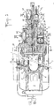
- a generator according to the invention essentially comprises a free piston engine designated by the general reference 1 and a hydraulic pump designated by the general reference 2.
- the engine 1 is constituted, as is known, by a combustion chamber 3 in which a piston 4 operates.
- the engine is of the two-stroke Diesel type.
- the piston 4 has at its end opposite to the combustion chamber an annular portion 5 evolving in a cylinder 6 and delimiting, on the one hand, a chamber 7, called pumping, and, on the other hand, a chamber 8, called bedroom-mattress.
- Valves 9 allow the chamber 7 to communicate with the atmosphere, while valves 10 open onto conduits 11 communicating with the combustion chamber, when the piston 4 releases the corresponding lights.
- a duct 12 schematically shown and provided with a valve 13 allows the filling of the mattress chamber 8 from the air contained in the pumping chamber 7, in particular to compensate for the air leaks occurring in this mattress chamber at during operation.
- the hydraulic pump 2 which is driven by the engine 1, is constituted by a body 14, fixed to the body of the engine, in which is formed a cylinder 15, preferably coaxial with the cylinder 6 of the engine and its combustion chamber 3. preferably also, the cylinder 15 is constituted by an attached jacket, mounted in the bore 14a of the body 14.
- the piston 16 of the pump is coupled to the piston 4 of the engine by means of a piston rod 17, coaxial with the latter and constituting with it a one-piece assembly.
- the piston 16 thus defines in the cylinder 15 two chambers 18 and 19, each of them being provided with at least one suction valve 20 and one discharge valve 21.
- Two sealing rings 25 and 25a close the chambers 18 and 19 and also ensure the immobilization of the cylinder 15 in the axial direction, while allowing the passage of the piston rod 17 under conditions which will be specified even more far.
- FIG. 1 represents an engine 1, the piston 4 of which receives the rod 17 of the piston 16 of the pump on its face opposite to the combustion chamber
- FIG. 1a shows an alternative embodiment which makes it possible to reduce the longitudinal dimensions of the generator.
- the face of the piston 4 opposite the combustion chamber is open and allows the latter to cover, at least in part, the body 14 of the pump, when the moving element is in the position shown in the Figure 1.
- the mattress chamber 8 then partially extends inside the piston 4, while the rod 17 of the piston 16 of the hydraulic pump is coupled to the piston 4 on its face limiting the combustion chamber.
- the piston rod 17 On the side opposite the piston 16, the piston rod 17 is extended by a coaxial rod 23 which moves outside the chamber 19 in a capacity 24 formed in a part 14b fixed to the body 14 of the pump.
- the sealing ring 25 crossed by the rod 23 avoids any communication between the chamber 19 and the capacity 24.
- the capacity 24 must have a variable volume.
- an accumulator 26 communicates by a conduit 27 with the capacity 24. It is constituted by a piston 28 evolving in a cylindrical chamber and subjected to the action of a spring 29.
- the two chambers 18 and 19 of the pump can be put in communication by a bypass device which will now be described.
- the conduits 30 and 31 communicating respectively with the chambers 18 and 19 open into a drawer distributor 32.
- the groove 33 of the drawer 32 ensures the communication of the conduits 30 and 31.
- the drawer 32 is however coupled to a piston 34 subjected to the action of a spring 35 and coming to rest bearing on the body 14 of the pump by its shoulder 34a.
- a control rod 36 capable of being coupled to a member for use, is slidably mounted in the part 14b of the pump body and allows the setting of the setting force of the spring 35.
- a chamber 37 formed in the body of the pump and one of the walls of which is constituted by the piston 34, communicates with the capacity 24 by a conduit 38.
- a pump for this purpose, there is firstly provided from the supply orifice 39 connected to a fluid reservoir, a pump, called a booster pump, designated by the general reference 40 and at least one accumulator 41 (FIGS. 3 and 5) regulating the discharge pressure of this booster pump.
- the booster pump consists of a piston 42 operating in a cylindrical chamber 43, one of the walls of which essentially consists of a plate 43a, com carries a suction valve 44 connected to the supply orifice 39.
- discharge valves 45 allow the communication of the chamber 43 with a chamber 46, itself connected to the supply conduits 22 by through a conduit 47 ( Figure 3). Bypassed on the conduit 47 is disposed the accumulator 41 comprising a piston 48 evolving in a chamber 49 and subjected to the action of a spring 50.
- the booster pump 40 or more precisely its delivery chamber 46, is on the other hand connected by a conduit 24a, equipped with a non-return valve 24b (shown diagrammatically by a dotted line in FIG. 3), to the variable volume capacity 24, so as to compensate for any leaks from the latter.
- a conduit 24a equipped with a non-return valve 24b (shown diagrammatically by a dotted line in FIG. 3), to the variable volume capacity 24, so as to compensate for any leaks from the latter.
- the piston 42 of the booster pump is driven by an auxiliary motor designated by the general reference 51.
- this engine comprises a piston 52 coupled to the piston 42 by means of a rod 53 and moving in a chamber 54 against the action of a spring 55 which bears on a ring 56 fixed to the body of the pump. In its rest position shown in FIG. 1, the piston 52 also bears on the body of the engine 1.
- the chamber 54, one of the walls of which is constituted by the piston 52 is in communication by a conduit 57 with the chamber - mattress 8 of engine 1.
- conduits 58 collect the fluid having passed through the valves 21 and are connected to a main discharge conduit 59 intended to be placed in communication with the user devices.
- a main discharge conduit 59 intended to be placed in communication with the user devices.
- an accumulator 60 On the conduit 59 is disposed bypass an accumulator 60, which, in the example shown, is of the membrane type.
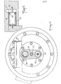
- FIGS. 8 and 9 essentially concern the structure of the body of the hydrau pump. 2, as well as the constitution of the booster pump 40 and its single accumulator 41, these last two members being arranged coaxially with the rod 17. This arrangement in fact makes it possible to reduce the size of the generator.
- the cylinder 15 of the pump has an outside diameter smaller than that of the bore 14a of the body 14 of the pump. It has at its left end (motor side) orifices 115, so that the chamber 18 opens into the annular space 118 located between the bore 14a and the cylinder 15. However, at its end opposite to the orifices 115, the cylinder 15 comprises a portion 115a, the outside diameter of which is identical to the inside diameter of the bore 14a: the annular space 118 can thus be isolated in a sealed manner from the chamber 19. Thanks to this arrangement, the suction valves 20 and of delivery 21 corresponding to the chamber 18 can be grouped in the vicinity of those which correspond to the chamber 19.
- This arrangement allows to clear the left side (motor side) of the pump 2 to place the booster pump 40 and the accumulator 41 in conditions which will be specified later.
- the action of the spring 35 on the slide 32 is exerted from the left to the right in FIG. 8 thanks to the lever 135.
- the drawer 32 ensures, by its groove 33, the communication between the conduits-30 and 31, while the piston 34 disposed at its end opposite the lever 135 bears directly by its shoulder 34a on the shoulder 114b of the part 14b fixed to the body 14 of the pump.
- the fluid contained in the capacity 24 and the accumulator 26 can act on the piston 34 in the direction opposite to the action of the spring 35.
- the booster pump 40 visible in FIG. 8 has a substantially different constitution from that described above, while comprising the same essential members.
- a casing 114 fixed to the motor 1 and having a central bore 114a, coaxial with the rod 17.
- An annular plate 43a is fixed in the space situated between the body 14 and the casing 114.
- plate 43a defines an annular chamber 43 in which the piston 42 of the booster pump moves.
- the face 152 of the piston 42 located on the side of the motor 1 closes the mattress chamber 8 and will thus constitute the piston 52 of the motor 51 of the booster pump.
- the piston 42 of the booster pump and the piston 52 of the motor 5L constitute a one-piece assembly.
- a ring 101 limits the axial movement of the piston 42-52 under the action of the spring 55 bearing on the plate 43a.
- the plate 43a On the side of the chamber 43, the plate 43a carries an annular suction valve 44 connected to the supply orifice 39. On the other side, the plate 43a carries an annular discharge valve 45 allowing the communication of the chamber 43 with a chamber 46, itself connected to the suction valves 20 of the pump 2 by the conduits 47 (formed in the casing 114) and 22 shown diagrammatically in FIG. 8.
- the chamber 46 is closed by the annular piston 48 of the shock absorber 41, this piston 48 being subjected to the action of the spring 50 bearing on the body 14 of the pump 2.
- the annular arrangement of the booster pump 40 and its accumulator 41 makes it possible to remove many dead spaces, such as the conduit 57 and the chamber 54 of the engine. 51, as well as the chamber 49 of the damper 41 which is here merged with the chamber 46.
- the conduits 47 and 22 may be shorter and less numerous than in the embodiment according to FIGS. 1 to 5.
- conduit 24a and its valve 24b the roles of which have been explained above, will be provided in the casing 114 and then in the body 14 of the pump, although they have been shown schematically in punted line figure 8.
- the operation of the pump 2 is then carried out in the following manner, whatever the embodiment.
- the "moving stroke” of the mobile assembly piston 4-rod 17-piston 16-rod 23 will denote its displacement under the effect of an explosion in the combustion chamber 3. In FIG. 1 and in FIG. 8, this movement takes place from left to right.
- the "return race” will designate the movement in the opposite direction of the moving equipment.
- the pump 2 provides its maximum flow rate, that is to say that the control rod 36 is in the position shown in the drawings, corresponding to the minimum setting force of the spring 35.
- the minimum pressure in the capacity 24 is sufficient to push the piston 34 completely against the action of the spring 35, the shoulder 34a then coming to bear on the stop 14c.
- the drawer 32 is thus maintained in its position obturation of the communication between the conduits 30 and 31.
- the volume of the chamber 18 increases and fills with fluid coming in particular from the accumulator or accumulators 41 through the suction valve or valves 20.
- the volume of the chamber 19 decreases and the fluid which it contains is discharged, through the corresponding valve 21, towards the accumulator 60 and from there towards the evacuation duct 59.
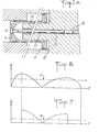
- FIG. 6 shows the graphical representation of the instantaneous flow rate Q of the pump 2 (that is to say of the quantity of liquid discharged per unit of time) as a function of time. Thanks to the presence of the accumulator 60, the average flow represented by the line A in dotted lines is almost constant despite the significant variations in instantaneous flow, on the one hand during a race of the moving assembly, on the other hand share between the "outward race” and the "return race".
- the average partial flow rate B (FIG. 7) of the pump can be adjusted to any desired value, by adjusting the compression of the spring 35 by the control rod 36. If the force of the spring 35 is sufficient to maintain permanently, whatever the pressure in the capacity 24, the slide 32 in the position shown in FIG. 1, the mean flow rate of the pump will be zero. The proper regulation of the motor 1 then acts on the latter to maintain its power at a minimum value, no loss of energy being thus recorded.
- the accumulator 60 is dimensioned in such a way that its capacity makes it possible to absorb and then restore the fluid discharged from the chambers 18 and 19, whatever the variations in the instantaneous flow rate, due to the operation as well at maximum average flow than at partial average flow.
- the fluid contained in the chamber 43 is then discharged by the valves 45 towards the chamber 46 and, beyond, towards the.or the accumulators 41 and the supply valves 20 by the conduits 47 and 22.
- the valves 20 do not open only to the extent that the chambers 18 and 19 need to be filled, which will not be the case during the phases of bringing these two chambers into communication with the drawer 32.
- the chamber 43 is filled through the valve 44 as a result of the vacuum created by the return of the piston 42, to the position shown in FIG. 1 or in FIG. 8, under the action of the spring 55.
Landscapes
- Engineering & Computer Science (AREA)
- Chemical & Material Sciences (AREA)
- Combustion & Propulsion (AREA)
- Mechanical Engineering (AREA)
- General Engineering & Computer Science (AREA)
- Reciprocating Pumps (AREA)
- Lubricants (AREA)
- Control Of Throttle Valves Provided In The Intake System Or In The Exhaust System (AREA)
- Braking Systems And Boosters (AREA)
- Lubrication Of Internal Combustion Engines (AREA)
- Electromagnetic Pumps, Or The Like (AREA)
- Servomotors (AREA)
- Nozzles (AREA)
- Fluid-Pressure Circuits (AREA)
Priority Applications (1)
| Application Number | Priority Date | Filing Date | Title |
|---|---|---|---|
| AT82400513T ATE13932T1 (de) | 1981-03-23 | 1982-03-22 | Hydraulische pumpe mit variablem hub und druckfluessigkeitserzeuger, der eine solche pumpe verwendet. |
Applications Claiming Priority (2)
| Application Number | Priority Date | Filing Date | Title |
|---|---|---|---|
| FR8105770 | 1981-03-23 | ||
| FR8105770A FR2502256A1 (fr) | 1981-03-23 | 1981-03-23 | Pompe hydraulique a piston a course variable et generateur faisant application de la pompe |
Publications (2)
| Publication Number | Publication Date |
|---|---|
| EP0061405A1 true EP0061405A1 (de) | 1982-09-29 |
| EP0061405B1 EP0061405B1 (de) | 1985-06-19 |
Family
ID=9256531
Family Applications (1)
| Application Number | Title | Priority Date | Filing Date |
|---|---|---|---|
| EP82400513A Expired EP0061405B1 (de) | 1981-03-23 | 1982-03-22 | Hydraulische Pumpe mit variablem Hub und Druckflüssigkeitserzeuger, der eine solche Pumpe verwendet |
Country Status (9)
| Country | Link |
|---|---|
| US (1) | US4461613A (de) |
| EP (1) | EP0061405B1 (de) |
| JP (1) | JPS57210179A (de) |
| AT (1) | ATE13932T1 (de) |
| BR (1) | BR8201628A (de) |
| CA (1) | CA1186947A (de) |
| DE (1) | DE3264219D1 (de) |
| ES (1) | ES510632A0 (de) |
| FR (1) | FR2502256A1 (de) |
Families Citing this family (1)
| Publication number | Priority date | Publication date | Assignee | Title |
|---|---|---|---|---|
| US5622142A (en) * | 1995-08-08 | 1997-04-22 | Strieber; Louis C. | Rotating piston engine with variable effective compression stroke |
Citations (7)
| Publication number | Priority date | Publication date | Assignee | Title |
|---|---|---|---|---|
| DE420266C (de) * | 1925-10-21 | Rudolf Ise | Zweitaktmotorpumpe | |
| US3065703A (en) * | 1960-11-03 | 1962-11-27 | Int Harvester Co | Free piston engine pump |
| GB1332799A (en) * | 1970-10-12 | 1973-10-03 | Riekkinen As | Hydraulic power unit including a hydraulic pump operated by a free piston internal combustion engine |
| FR2217529A1 (de) * | 1971-11-18 | 1974-09-06 | Fitzgerald William | |
| DE2648958A1 (de) * | 1976-10-28 | 1978-05-03 | Fengler Karl Heinz | Hydraulische kolbenpumpe mit antrieb durch freiflugkolben |
| US4097198A (en) * | 1974-09-18 | 1978-06-27 | Herron Allen R | Internal combustion assisted hydraulic engine |
| DE2758182A1 (de) * | 1976-12-30 | 1978-07-13 | Dewandre Co Ltd C | Hydraulische pumpe |
Family Cites Families (8)
| Publication number | Priority date | Publication date | Assignee | Title |
|---|---|---|---|---|
| US689272A (en) * | 1899-06-29 | 1901-12-17 | Armand Bailly | Blowing-engine. |
| US1001295A (en) * | 1909-08-10 | 1911-08-22 | Albert E Moorhead | Automatic by-pass for pumps. |
| US2387603A (en) * | 1940-10-22 | 1945-10-23 | Neugebauer Franz | Free piston motor compressor |
| US2667300A (en) * | 1949-06-14 | 1954-01-26 | Participations Soc Et | Free piston machine the compressor portion of which includes at least two stages |
| US3012509A (en) * | 1957-03-22 | 1961-12-12 | Mercier Jean | Differential pumps |
| NL160632C (nl) * | 1968-10-08 | 1979-11-15 | Ir Theodorus Gerhardus Potma | Vrije-zuigerpompinstallatie. |
| US4307999A (en) * | 1979-06-25 | 1981-12-29 | Pneumo Corporation | Free piston engine pump including variable energy rate and acceleration-deceleration controls |
| US4382748A (en) * | 1980-11-03 | 1983-05-10 | Pneumo Corporation | Opposed piston type free piston engine pump unit |
-
1981
- 1981-03-23 FR FR8105770A patent/FR2502256A1/fr active Granted
-
1982
- 1982-03-19 US US06/359,995 patent/US4461613A/en not_active Expired - Fee Related
- 1982-03-22 DE DE8282400513T patent/DE3264219D1/de not_active Expired
- 1982-03-22 AT AT82400513T patent/ATE13932T1/de not_active IP Right Cessation
- 1982-03-22 CA CA000398991A patent/CA1186947A/en not_active Expired
- 1982-03-22 EP EP82400513A patent/EP0061405B1/de not_active Expired
- 1982-03-22 ES ES510632A patent/ES510632A0/es active Granted
- 1982-03-23 JP JP57046156A patent/JPS57210179A/ja active Pending
- 1982-03-23 BR BR8201628A patent/BR8201628A/pt unknown
Patent Citations (7)
| Publication number | Priority date | Publication date | Assignee | Title |
|---|---|---|---|---|
| DE420266C (de) * | 1925-10-21 | Rudolf Ise | Zweitaktmotorpumpe | |
| US3065703A (en) * | 1960-11-03 | 1962-11-27 | Int Harvester Co | Free piston engine pump |
| GB1332799A (en) * | 1970-10-12 | 1973-10-03 | Riekkinen As | Hydraulic power unit including a hydraulic pump operated by a free piston internal combustion engine |
| FR2217529A1 (de) * | 1971-11-18 | 1974-09-06 | Fitzgerald William | |
| US4097198A (en) * | 1974-09-18 | 1978-06-27 | Herron Allen R | Internal combustion assisted hydraulic engine |
| DE2648958A1 (de) * | 1976-10-28 | 1978-05-03 | Fengler Karl Heinz | Hydraulische kolbenpumpe mit antrieb durch freiflugkolben |
| DE2758182A1 (de) * | 1976-12-30 | 1978-07-13 | Dewandre Co Ltd C | Hydraulische pumpe |
Also Published As
| Publication number | Publication date |
|---|---|
| JPS57210179A (en) | 1982-12-23 |
| BR8201628A (pt) | 1983-02-16 |
| ES8400802A1 (es) | 1983-11-01 |
| CA1186947A (en) | 1985-05-14 |
| EP0061405B1 (de) | 1985-06-19 |
| FR2502256B1 (de) | 1984-07-13 |
| DE3264219D1 (en) | 1985-07-25 |
| US4461613A (en) | 1984-07-24 |
| ATE13932T1 (de) | 1985-07-15 |
| FR2502256A1 (fr) | 1982-09-24 |
| ES510632A0 (es) | 1983-11-01 |
Similar Documents
| Publication | Publication Date | Title |
|---|---|---|
| EP1048849B1 (de) | Flüssigkeitshochdruckpumpe | |
| FR2552172A1 (fr) | Verin pneumatique a mecanisme d'amortissement et procede d'amortissement d'un verin pneumatique | |
| EP0461943A2 (de) | Verdichtungsvorrichtung, insbesondere zur Druckfüllung eines Behälters | |
| FR2492473A1 (fr) | Pompe a membrane a compensation dans la chambre hydraulique de commande | |
| CA2074955A1 (fr) | Dispositif pour l'injection d'un liquide, a savoir du carburant, dans au moins une des chambres pressurisees d'une machine fonctionnant de facon periodique tel qu'un moteur a combustion interne ou semblable | |
| EP1464912B1 (de) | Vorrichtung zur Rückgewinnung von der Rückstossenergie einer Waffe | |
| FR2716494A1 (fr) | Machine à pistons rotatifs utilisable notamment en tant que moteur thermique. | |
| WO2007110492A1 (fr) | Pompe transfert pour injection d'essence a haute pression | |
| EP0061405B1 (de) | Hydraulische Pumpe mit variablem Hub und Druckflüssigkeitserzeuger, der eine solche Pumpe verwendet | |
| FR2551139A1 (fr) | Demarreur a commande par air comprime, notamment pour moteurs a combustion interne | |
| EP0283348B1 (de) | Hydraulische Pumpen | |
| FR2640698A1 (fr) | Pompe peristaltique | |
| EP0351277B1 (de) | Dichtungseinrichtung zwischen den beweglichen Teilen einer Geschützrücklaufbremse | |
| EP0731886A1 (de) | Schmiervorrichtung eines zusammenbaus von zwei mechanisch verbundenen teilen, bzw. kolben und pleuelstange | |
| FR2485110A1 (fr) | Dispositif pour produire successivement des debits de fluide hydraulique de valeurs echelonnees | |
| EP1748194A1 (de) | Vorrichtung zur Erhöhung des Druckes für eine hydraulische Verstelleinrichtung in einer Brennkraftmaschine und Brennkraftmaschine mit einer solchen Einrichtung | |
| FR2711433A1 (fr) | Régulateur coaxial de débit. | |
| FR2518657A1 (fr) | Piston d'obturation pour pompe a cylindree fixe | |
| WO2021111088A1 (fr) | Systeme hydraulique de commande pour un moteur a taux de compression variable | |
| FR2515256A1 (fr) | Pompe mixte a carburant et huile actionnee par pression | |
| EP0624719A1 (de) | Druckbegrenzungsvorrichtung in einem Schmierkreislauf einer Brennkraftmaschine | |
| BE1015545A3 (fr) | Systeme de transformation d'energie a appareil volumetrique. | |
| CH640310A5 (en) | Hydraulic pump with a sprung valve | |
| EP0086725A1 (de) | Druckflüssigkeitserzeuger | |
| FR2722840A1 (fr) | Dispositif de pompage pour presse d'injection |
Legal Events
| Date | Code | Title | Description |
|---|---|---|---|
| PUAI | Public reference made under article 153(3) epc to a published international application that has entered the european phase |
Free format text: ORIGINAL CODE: 0009012 |
|
| AK | Designated contracting states |
Designated state(s): AT BE CH DE FR GB IT NL SE |
|
| 17P | Request for examination filed |
Effective date: 19820826 |
|
| ITF | It: translation for a ep patent filed | ||
| GRAA | (expected) grant |
Free format text: ORIGINAL CODE: 0009210 |
|
| AK | Designated contracting states |
Designated state(s): AT BE CH DE FR GB IT LI NL SE |
|
| REF | Corresponds to: |
Ref document number: 13932 Country of ref document: AT Date of ref document: 19850715 Kind code of ref document: T |
|
| REF | Corresponds to: |
Ref document number: 3264219 Country of ref document: DE Date of ref document: 19850725 |
|
| PG25 | Lapsed in a contracting state [announced via postgrant information from national office to epo] |
Ref country code: AT Effective date: 19860322 |
|
| PG25 | Lapsed in a contracting state [announced via postgrant information from national office to epo] |
Ref country code: SE Effective date: 19860323 |
|
| PG25 | Lapsed in a contracting state [announced via postgrant information from national office to epo] |
Ref country code: LI Effective date: 19860331 Ref country code: CH Effective date: 19860331 Ref country code: BE Effective date: 19860331 |
|
| PLBE | No opposition filed within time limit |
Free format text: ORIGINAL CODE: 0009261 |
|
| STAA | Information on the status of an ep patent application or granted ep patent |
Free format text: STATUS: NO OPPOSITION FILED WITHIN TIME LIMIT |
|
| 26N | No opposition filed | ||
| BERE | Be: lapsed |
Owner name: POCLAIN HYDRAULICS S.A. DE DROIT FRANCAIS Effective date: 19860331 Owner name: AIRMACHINES Effective date: 19860331 |
|
| PG25 | Lapsed in a contracting state [announced via postgrant information from national office to epo] |
Ref country code: NL Effective date: 19861001 |
|
| GBPC | Gb: european patent ceased through non-payment of renewal fee | ||
| PG25 | Lapsed in a contracting state [announced via postgrant information from national office to epo] |
Ref country code: FR Free format text: LAPSE BECAUSE OF NON-PAYMENT OF DUE FEES Effective date: 19861128 |
|
| REG | Reference to a national code |
Ref country code: CH Ref legal event code: PL |
|
| PG25 | Lapsed in a contracting state [announced via postgrant information from national office to epo] |
Ref country code: DE Effective date: 19861202 |
|
| NLV4 | Nl: lapsed or anulled due to non-payment of the annual fee | ||
| REG | Reference to a national code |
Ref country code: FR Ref legal event code: ST |
|
| PG25 | Lapsed in a contracting state [announced via postgrant information from national office to epo] |
Ref country code: GB Effective date: 19881121 |
|
| EUG | Se: european patent has lapsed |
Ref document number: 82400513.6 Effective date: 19870224 |