EP0061524A1 - Méthode pour la transmission bidirectionnelle de signaux de données binaires sur une ligne de transmission de signaux qui est fermée des deux côtés par un transformateur - Google Patents
Méthode pour la transmission bidirectionnelle de signaux de données binaires sur une ligne de transmission de signaux qui est fermée des deux côtés par un transformateur Download PDFInfo
- Publication number
- EP0061524A1 EP0061524A1 EP81108930A EP81108930A EP0061524A1 EP 0061524 A1 EP0061524 A1 EP 0061524A1 EP 81108930 A EP81108930 A EP 81108930A EP 81108930 A EP81108930 A EP 81108930A EP 0061524 A1 EP0061524 A1 EP 0061524A1
- Authority
- EP
- European Patent Office
- Prior art keywords
- pulse
- transmission
- information
- binary
- pulses
- Prior art date
- Legal status (The legal status is an assumption and is not a legal conclusion. Google has not performed a legal analysis and makes no representation as to the accuracy of the status listed.)
- Granted
Links
- 230000005540 biological transmission Effects 0.000 title claims abstract description 42
- 238000000034 method Methods 0.000 title claims abstract description 16
- 230000002457 bidirectional effect Effects 0.000 title 1
- 206010010904 Convulsion Diseases 0.000 claims abstract description 3
- 230000008054 signal transmission Effects 0.000 claims abstract description 3
- 238000004804 winding Methods 0.000 description 14
- 238000011156 evaluation Methods 0.000 description 8
- 230000011664 signaling Effects 0.000 description 8
- 238000010586 diagram Methods 0.000 description 5
- 230000003287 optical effect Effects 0.000 description 4
- 230000008569 process Effects 0.000 description 4
- 230000004913 activation Effects 0.000 description 2
- 230000008859 change Effects 0.000 description 2
- 230000008878 coupling Effects 0.000 description 2
- 238000010168 coupling process Methods 0.000 description 2
- 238000005859 coupling reaction Methods 0.000 description 2
- 230000000694 effects Effects 0.000 description 2
- 238000011017 operating method Methods 0.000 description 2
- 230000004044 response Effects 0.000 description 2
- 230000000284 resting effect Effects 0.000 description 2
- 230000000630 rising effect Effects 0.000 description 2
- 230000001960 triggered effect Effects 0.000 description 2
- 239000003990 capacitor Substances 0.000 description 1
- 239000000284 extract Substances 0.000 description 1
- 238000003780 insertion Methods 0.000 description 1
- 230000037431 insertion Effects 0.000 description 1
- 230000009467 reduction Effects 0.000 description 1
Images
Classifications
-
- H—ELECTRICITY
- H04—ELECTRIC COMMUNICATION TECHNIQUE
- H04L—TRANSMISSION OF DIGITAL INFORMATION, e.g. TELEGRAPHIC COMMUNICATION
- H04L25/00—Baseband systems
- H04L25/38—Synchronous or start-stop systems, e.g. for Baudot code
- H04L25/40—Transmitting circuits; Receiving circuits
- H04L25/49—Transmitting circuits; Receiving circuits using code conversion at the transmitter; using predistortion; using insertion of idle bits for obtaining a desired frequency spectrum; using three or more amplitude levels ; Baseband coding techniques specific to data transmission systems
- H04L25/4906—Transmitting circuits; Receiving circuits using code conversion at the transmitter; using predistortion; using insertion of idle bits for obtaining a desired frequency spectrum; using three or more amplitude levels ; Baseband coding techniques specific to data transmission systems using binary codes
-
- H—ELECTRICITY
- H04—ELECTRIC COMMUNICATION TECHNIQUE
- H04M—TELEPHONIC COMMUNICATION
- H04M9/00—Arrangements for interconnection not involving centralised switching
- H04M9/002—Arrangements for interconnection not involving centralised switching with subscriber controlled access to a line, i.e. key telephone systems
- H04M9/003—Transmission of control signals from or to the key telephone set; signalling equipment at key telephone set, e.g. keyboard or display equipment
Definitions
- the invention relates to a method for the mutual transmission of binary data signals via a signal line which is symmetrically terminated on both sides with a transmitter and connected to a transmitting / receiving unit, wherein a bitwise interleaving of the data signals assigned to the two directions is made within a data block having a fixed predetermined number of binary characters is made, in particular for small private branch exchanges in which, among other things, between the subscriber terminals and a central facility to transmit the dialing information used to establish the connection and entered by the subscriber or information on line seizures and to transmit optically and / or acoustically registered on the subscriber terminal device by means of appropriately controlled display elements, certain states of the call connection and the system relating to signal transmission via the intended and with the - Signal academy forming a connecting line for each speech academy.
- a mutually directed signaling takes place between the individual terminal devices and a device common to them.
- These terminals can be, for example, the individual speech devices of the subscriber stations of a small private branch exchange. To them from the central device, setting information for display elements attached to them are transmitted. If these display elements are of an optical type, they can be formed by so-called light-emitting diodes and / or by a display.
- a subscriber of this type can be used to inform a subscriber, for example, of the number dialed by him or of the call charges that have accrued.
- the light status of the existing optical display elements which can be set on the basis of the transmitted signals, can be used to indicate to a subscriber whether, for example, the external lines or the internal lines provided for the system are free or busy. Furthermore, information can be transmitted that the delivery of acoustic. Concern signals at the respective subscriber station. Depending on whether the connection request is from an internal or an external subscriber, different call signals could be triggered, for example. In this way it would be possible to determine the type of origin of the desired call connection.
- switching elements which are designed as keys, represent, for example, selection keys. Further keys can be provided which enable certain operating procedures or, by actuating them, the type of the intended connection can be signaled.
- a distinction can be made in the central device as to whether an internal connection to another intercom of the respective private branch exchange or whether an external connection to a public intercom Lichen network or to a telephone of another private branch exchange.
- the bitwise interleaving of the information bits to be mutually assigned to the two directions within a data block requires an exact timing of the respective transmission times.
- the clock which is the basis for the transmission of the information bits in the respective terminal device must be matched to the clock which determines the transmission of the information bits in the central device.
- This requires mutual synchronization of the respective oscillators from which the clock is derived. It is the object of the invention to enable this synchronization in the case of a method for the mutual transmission of binary data signals with the least possible outlay for the existing oscillators and at the same time to ensure a high evaluation reliability.
- this is achieved by using pulses of the same polarity in one transmission direction to identify the two binary values, which differ both in their duration and in their pulse amplitude in such a way that the pulse has a shorter duration has a higher and approximate pulse area as in the case of the other pulse type, that at least the time period specified between them is defined as the pause time between the data blocks, that in the other transmission direction pulses with such a shape and amplitude are selected to represent the binary values that at their insertion through the swing-out behavior the line certain potential relationships correspond approximately to those that occur with two successive, uninfluenced pulses of the first type.
- the ratios that result from the pulses emitted in one direction can be kept unchanged when transmitting in the opposite direction if a bipolar pulse of suitable dimension for the representation of one binary value and one for the representation of the other binary value Quiescent potential of the line corresponding pulse-free state is used.
- a specially designed pulse is used as the active binary character.
- This pulse which is inserted between two successive pulses of the forward direction which define the bit frames, preferably represents a bipolar pulse shaped in such a way that the line at the end of the bit frame has the same potential that it would have if no such pulse had been faded in . A disadvantageous additional level shift is thus prevented.
- the result of this is that the receiving circuit for the pulses of the forward direction can have a high evaluation threshold, which increases the security against disturbances.
- each of these can be properly received via an evaluating control unit registering pulses are derived from a synchronization pulse for a clocking unit.
- the beginning of a data block can be recognized in a simple manner by evaluating the pause provided between the data blocks, which corresponds, for example, to the time period provided for the bit frame. By evaluating the pause, interference pulses cannot have a disadvantageous effect.
- a further synchronization pulse for synchronizing the control processes in the central device and in the subscriber terminals can be obtained.
- the solution according to the invention for data transmission therefore differs in several respects from a known transmission method in which such a reduction in the amplitude of the pulse compensation to compensate for pulse distortions
- the trailing edge of the respective individual pulse has the effect that the subsequent pulse is no longer influenced in an undesirable manner. This is also possible in cases where an additional pulse to be assigned to the other direction is inserted between the individual pulses of the same direction. (DE-AS 27 42 301).
- the unipolar impulses are selected as binary characters for the direction in which there is a significantly higher information flow than in the opposite direction.
- this is the case for the information to be transmitted from the central facility to the individual terminals.
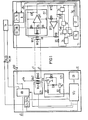
- FIG. 1 shows in part a small private branch exchange in which the microphone units are connected to a facility common to them and in which the method according to the invention can be used for the mutual transmission of information.
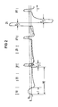
- FIG. 2 shows a pulse diagram representing the binary values used.
- a small private branch exchange is shown in extracts, in which a small number of call stations T1 to Tn are each connected in a star shape via a multi-core connecting line to the unit ZE which fulfills them control and switching functions.
- Each subscriber line consists of at least one pair of speech wires a, b and one pair of signaling wires c, d.
- all other wire pairs are shown in simplified single-wire fashion.
- a speech circuit SS is connected to the speech wires leading to each speech station, eg speech wires a1 and bl, as indicated for the speech station T1. It is used in conjunction with the handset HA to process the transmitted voice information and forms the line termination. Internal connections can be established between the individual speech devices T and there is also the possibility of connecting to one of several external lines EL. These can lead to an exchange in the public telephone network or to another private branch exchange.
- the unit TA is intended to indicate the possibility that certain information can be sent out by pressing buttons.
- there may be other keys which, when pressed, initiate certain operating procedures.
- the respective key actuation is registered by a control unit ST present in each telephone set.
- This control unit which can represent a processor, then initiates the transmission of the relevant information to the central unit ZE by influencing a corresponding transmission arrangement.
- the signaling carried out by binary data signals takes place via the signaling wires Q1, d1, which are terminated on both sides with a transformer Ut or Uz, in that the transmission winding Wt2 is activated according to the bit pattern to be assigned in each case.
- the transmitted information is registered by a receiving circuit EZ, which is available individually for each speech apparatus, and is sent to a control unit STz for evaluation.
- the talk Apparatus T1 is therefore assigned to the receiving circuit EZ1 in the central unit.
- The. Control unit STz also supplies the setting and switching commands necessary for establishing a voice connection for the coupling contacts contained in the existing coupling arrangement KN. In addition, it controls a transmitting unit SZ, through which information about the individual speech devices is transmitted.
- the transmitting circuit SZ1 is decisive for the speech apparatus T1 and is coupled to the signaling wires of the connecting line leading to the telephone apparatus T1 via the transmission winding of the assigned transmitter Uz.
- the central of the unit to the individual appliances S p accounting-information submitted concerning, for example, setting information for optical display elements A, which are attached to the respective telephone set. It can be used, for example, to determine the busy status of the individual internal or External lines are displayed.
- the information transmitted is registered by the receiving unit EF and fed to the control unit ST. This then initiates the activation of the optical display elements in accordance with the information content.
- Acoustic signal transmitters which make it possible to differentiate between certain operating modes, could also be activated on the basis of information transmitted in this regard.
- the sequence of the binary values within an information block to be formed is determined by the control unit STz and, based on the bit pattern thus specified, the two transistors T1 and T2 of the transmission unit SZ1 shown in the details are controlled. If, for example, control potential for the transistor T1 is applied via the base series resistor R1 during the time period T / 2, the transmission winding Wz2 of the transformer Uz is traversed by the current during the control time. As a result, a pulse of width T / 2 is induced in the line-side winding Wz3.
- control unit STz applies control potential for the transistor T2 via the base resistor R2 for a period T
- the transmission winding is connected to the supply voltage via the series resistor R3 during this time, while the transistor T1 is blocked via the diode D.
- a pulse of width T is induced in the line-side winding Wz3, which pulse has a smaller amplitude than the first-mentioned pulse.
- the amplitudes for the generated pulses are determined in such a way that the product of the pulse duration and the relevant amplitude approximates the same value for both pulse types results. In the illustration in FIG.
- each telephone set T. circuit for example the receiving circuit EF for the speech apparatus T1
- a fixed response threshold for the operational amplifier is specified by the divider circuit formed from the resistors R4 to R6.
- Each receive pulse of a bit cycle BZ leads to a change in the output signal of the operational amplifier, which is registered by the control unit ST.
- the information contained in the transmitted bit pattern within a data block formed is recognized and the corresponding follow-up functions are initiated. These consist, for example, of a corresponding activation of the display elements contained in display unit A.
- a synchronization pulse can be derived in every bit cycle BZ for the clock-generating unit Oz present in each telephone set.
- This unit supplies the clock sequences necessary for the control processes via correspondingly switched on divider stages.
- An inexpensive oscillator with lower frequency constancy can thus be used. It is a prerequisite that the information bits emitted by the individual speech apparatuses in the case of mutual signaling are interleaved bit by bit within a data block formed with the information bits transmitted by the central unit ZE. This requires a precise timing of the respective transmission times, which is possible by deriving the synchronization pulses mentioned. This can be done by inserting the pause between the data blocks Be recognized at the end of each data block.
- a bipolar pulse Z1 is used to represent the binary value 1 and the pulse-free state is used to represent the binary value 0.
- the information bit ZO defined by the latter is recognized as such by the correct evaluation in time at the head office.
- the bipolar pulse shown in the diagram in FIG. 2 has a substantially higher amplitude than the incoming pulses, since - as already mentioned - the voltage conditions / the line are shown directly on the telephone set.
- the dimensions of the bipolar pulse are determined in such a way that it must be inserted between two incoming pulses at the correct time without the potential relationships on the rising flank of the pulse received after it being temporally changed compared to the relationships which arise when two such pulses which follow one another uninfluenced occur.
- the control unit ST emits a control signal at the output Se, which has the duration T, for example.
- the NOR gate I3 is unlocked, so that the pulse generated by the multivibrator at the output of the switch I5 and thus also via the resistor R9, at the inverting input of the operational amplifier OP2.
- the output of the operational amplifier is set to the potential U / 2 as the output state via the adjustable resistor R5, so that the transmission winding Wt2 of the transformer Ut lies between the potentials U and U / 2.
- the output of the operational amplifier is switched to approximately 0 volts and to the supply voltage potential U during the remaining period of the drive pulse applied by the control unit ST.
- the multivibrator and the switch 15 are blocked, so that the output of the operational amplifier again assumes the output potential U / 2.
- the potential on the side of the transmission winding Wt2 connected to it is first lowered from the value U / 2 to the value 0 via the operational amplifier.
- a positively directed pulse of duration T / 2 is induced in the line-side winding Wt3.
- a current decrease in the transmission winding is carried out due to the raising of the potential from the value 0 to the value U.
- a negatively directed pulse of the duration T / 2 is induced in the line-side winding Wt3.
- a bipolar pulse Z1 with the total time period T is thus transmitted on the line at the point in time determined by the control unit ST on the basis of the bit pattern to be transmitted.
- This is registered by the receiving circuit EZ present in the central unit ZE and coupled to the respective signal line via a transmitter Uz.
- the receiving circuit EZ1 assigned to the signal wires c1, d1 only the receiving side is used Winding Wz1 of the transformer shown.
- the information bits received are evaluated by the control unit STz, which then also initiates the corresponding follow-up functions.
- the information transmitted by the speech apparatus which therefore primarily contains statements about the actuation of certain keys, can be stored, for example, in the storage device SR, which can also contain information about individual control processes and connection states.
- the bipolar pulse emitted by a telephone set as an active binary character is also registered by the reception winding Wt1 in the arrangement of the exemplary embodiment and transferred to the evaluating control unit via the comparator. Since this control unit determines the time of transmission, it can be ensured that the relevant output information of the comparator is not evaluated.
Landscapes
- Engineering & Computer Science (AREA)
- Signal Processing (AREA)
- Physics & Mathematics (AREA)
- Spectroscopy & Molecular Physics (AREA)
- Computer Networks & Wireless Communication (AREA)
- Sub-Exchange Stations And Push- Button Telephones (AREA)
- Dc Digital Transmission (AREA)
- Arrangements For Transmission Of Measured Signals (AREA)
Priority Applications (1)
| Application Number | Priority Date | Filing Date | Title |
|---|---|---|---|
| AT81108930T ATE12868T1 (de) | 1981-03-31 | 1981-10-26 | Verfahren zur wechselseitigen uebertragung von binaeren daten-signalen ueber eine beidseitig mit einem uebertrager abgeschlossene signalleitung. |
Applications Claiming Priority (2)
| Application Number | Priority Date | Filing Date | Title |
|---|---|---|---|
| DE3112847 | 1981-03-31 | ||
| DE3112847A DE3112847C2 (de) | 1981-03-31 | 1981-03-31 | Verfahren zur wechselseitigen Übertragung von binären Datensignalen über eine beidseitig mit einem Übertrager abgeschlossene Signalleitung |
Publications (2)
| Publication Number | Publication Date |
|---|---|
| EP0061524A1 true EP0061524A1 (fr) | 1982-10-06 |
| EP0061524B1 EP0061524B1 (fr) | 1985-04-17 |
Family
ID=6128894
Family Applications (1)
| Application Number | Title | Priority Date | Filing Date |
|---|---|---|---|
| EP81108930A Expired EP0061524B1 (fr) | 1981-03-31 | 1981-10-26 | Méthode pour la transmission bidirectionnelle de signaux de données binaires sur une ligne de transmission de signaux qui est fermée des deux côtés par un transformateur |
Country Status (8)
| Country | Link |
|---|---|
| EP (1) | EP0061524B1 (fr) |
| AR (1) | AR230908A1 (fr) |
| AT (1) | ATE12868T1 (fr) |
| AU (1) | AU548150B2 (fr) |
| BR (1) | BR8201815A (fr) |
| DE (1) | DE3112847C2 (fr) |
| FI (1) | FI74852C (fr) |
| NO (1) | NO155749C (fr) |
Families Citing this family (4)
| Publication number | Priority date | Publication date | Assignee | Title |
|---|---|---|---|---|
| DE3139511C2 (de) * | 1981-09-30 | 1983-08-18 | Siemens AG, 1000 Berlin und 8000 München | Verfahren zur Synchronisation von wechselseitig über eine Signalleitung übertragenen binären Datensignalen |
| DE4114485A1 (de) * | 1991-05-03 | 1992-11-05 | Kommunikations Elektronik | Verfahren zur bidirektionalen datenuebertragung |
| DE4405038A1 (de) * | 1994-02-17 | 1995-08-24 | Sel Alcatel Ag | Netzabschlußeinrichtung eines Telekommunikationsnetzes |
| AU692201B2 (en) * | 1994-02-17 | 1998-06-04 | Alcatel N.V. | Network termination unit |
Citations (4)
| Publication number | Priority date | Publication date | Assignee | Title |
|---|---|---|---|---|
| FR2224958A1 (fr) * | 1973-04-04 | 1974-10-31 | Plessey Handel Investment Ag | |
| US4125749A (en) * | 1975-08-09 | 1978-11-14 | Tamura Electric Works, Ltd. | Key telephone systems |
| US4170715A (en) * | 1976-08-07 | 1979-10-09 | Hitachi, Ltd. | Data communication system |
| US4219890A (en) * | 1977-07-01 | 1980-08-26 | The General Corporation | Digital signal regulation system |
Family Cites Families (2)
| Publication number | Priority date | Publication date | Assignee | Title |
|---|---|---|---|---|
| JPS5321963B2 (fr) * | 1973-11-12 | 1978-07-06 | ||
| DE2742301C3 (de) * | 1977-09-20 | 1980-07-17 | Siemens Ag, 1000 Berlin Und 8000 Muenchen | Kompensation von Impulsverzerrungen |
-
1981
- 1981-03-31 DE DE3112847A patent/DE3112847C2/de not_active Expired
- 1981-10-26 EP EP81108930A patent/EP0061524B1/fr not_active Expired
- 1981-10-26 AT AT81108930T patent/ATE12868T1/de not_active IP Right Cessation
-
1982
- 1982-03-05 AR AR288652A patent/AR230908A1/es active
- 1982-03-30 AU AU82149/82A patent/AU548150B2/en not_active Ceased
- 1982-03-30 BR BR8201815A patent/BR8201815A/pt unknown
- 1982-03-30 NO NO821055A patent/NO155749C/no unknown
- 1982-03-30 FI FI821097A patent/FI74852C/fi not_active IP Right Cessation
Patent Citations (4)
| Publication number | Priority date | Publication date | Assignee | Title |
|---|---|---|---|---|
| FR2224958A1 (fr) * | 1973-04-04 | 1974-10-31 | Plessey Handel Investment Ag | |
| US4125749A (en) * | 1975-08-09 | 1978-11-14 | Tamura Electric Works, Ltd. | Key telephone systems |
| US4170715A (en) * | 1976-08-07 | 1979-10-09 | Hitachi, Ltd. | Data communication system |
| US4219890A (en) * | 1977-07-01 | 1980-08-26 | The General Corporation | Digital signal regulation system |
Non-Patent Citations (1)
| Title |
|---|
| INTERNATIONAL CONFERENCE ON PRIVATE ELECTRONIC SWITCHING SYSTEMS, 10.-12. April 1978, Seiten 64-69, London, G.B. * |
Also Published As
| Publication number | Publication date |
|---|---|
| EP0061524B1 (fr) | 1985-04-17 |
| DE3112847C2 (de) | 1983-02-03 |
| ATE12868T1 (de) | 1985-05-15 |
| FI821097A0 (fi) | 1982-03-30 |
| FI74852C (fi) | 1988-03-10 |
| NO155749B (no) | 1987-02-09 |
| AU8214982A (en) | 1982-10-07 |
| NO155749C (no) | 1987-05-20 |
| AU548150B2 (en) | 1985-11-28 |
| FI821097L (fi) | 1982-10-01 |
| BR8201815A (pt) | 1983-03-01 |
| NO821055L (no) | 1982-10-01 |
| DE3112847A1 (de) | 1982-10-14 |
| FI74852B (fi) | 1987-11-30 |
| AR230908A1 (es) | 1984-07-31 |
Similar Documents
| Publication | Publication Date | Title |
|---|---|---|
| EP0061524B1 (fr) | Méthode pour la transmission bidirectionnelle de signaux de données binaires sur une ligne de transmission de signaux qui est fermée des deux côtés par un transformateur | |
| DE2146109C3 (de) | Schaltungsanordnung zum Sperren eines insbesondere an eine Nebenstellenanlage angeschlossenen Fernsprechapparates | |
| DE2518126C2 (de) | Einrichtung zum Empfang von Wählimpulsen | |
| DE3607717C2 (fr) | ||
| DE2722393A1 (de) | Ueberlappender pcm-kodierer/dekodierer mit reaktionszeitkompensation | |
| DE3036240C2 (de) | Verfahren zur Übertragung von Binärzeichen zwischen einer zentralen Einrichtung und einer Anzahl von Teilnehmerstellen bei Fernsprechvermittlungsanlagen | |
| DE3036182C2 (de) | Verfahren zur wechselseitigen Übertragung von binären Digitalsignalen zwischen einer zentralen Einrichtung und mit ihr verbundenen Fernsprechteilnehmerstellen | |
| DE3112846A1 (de) | Verfahren fuer die uebertragung von binaer- impulsdauermodulierten signalen in fernsprechvermittlungsanlagen, insbesondere in kleinen nebenstellenanlagen | |
| DE3036183C2 (de) | Schaltungsanordnung zur Aussendung von digitalen Datensignalen von einer zentralen Einrichtung zu Teilnehmerstellen kleiner Nebenstellenanlagen | |
| DE3112894C2 (de) | Sende- und Empfangseinheit für in Fernsprechvermittlungsanlagen, insbesondere in kleinen Nebenstellenanlagen zu übertragende binäre Steuerdatensignale | |
| DE4111301A1 (de) | Verfahren und kommunikationssystem zum uebertragen von seriellen daten | |
| EP0004867B1 (fr) | Circuit pour postes d'abonnés dans des installations téléphoniques privées à sélection au clavier par fréquences vocales | |
| DE2831145C2 (de) | Schaltungsanordnung für Teilnehmerapparate in Fernsprechnebenstellenanlagen mit tonfrequenter Tastwahl der Nebenstellenteilnehmer | |
| DE3427140C1 (de) | Einrichtung zur Übertragung von Daten über eine Fernsprechleitung | |
| DE2452699C3 (de) | Verfahren zur Bestätigung der richtigen Verbindung zwischen zwei Datenendstellen | |
| DE3036204C2 (de) | Empfangsschaltung in kleinen Fernsprech-Nebenstellenanlagen für über das Signalisierungsadernpaar einer vieradrigen Teilnehmeranschlußleitung übertragene binäre Digitalsignale, deren Binärwerte unterschiedlichen Spannungswerten entsprechen | |
| DE1762969C (de) | Schaltungsanordnung zum Anzeigen der Berechtigungsklasse in Fernmeldevermittlungsanlagen. Ausscheidung aus: 1412985 | |
| EP0246480B1 (fr) | Circuit dans des centraux téléphoniques pour l'évaluation de signes binaires, dont la valeur binaire est formée par des valeurs de courant fixées qui sont différentes l'une de l'autre | |
| DE1766628C3 (de) | Sende- und Empfangseinrichtung für ein Duplexfunk-Fernsprechnetz | |
| DE2219104C3 (de) | Schaltungsanordnung für Fernmeldeanlagen, in denen die Verbindungswege für verschiedene Arten der Nachrichtenübermittlung, z.B. Fernsprechen und Datenübertragung, benutzbar sind Siemens AG, 1000 Berlin und 8000 München | |
| DE3036205A1 (de) | Verfahren zur wechselseitigen uebertragung von binaeren digitalsignalen zwischen einer zentralen einrichtung und mit ihr verbundenen endeinrichtung | |
| DE1920677B1 (de) | Schaltungsanordnung fuer Fernmeldeanlagen,in denen Verbindungswege fuer verschiedene Arten der Nachrichtenuebermittlung benutzbar sind | |
| DE2656087A1 (de) | Verfahren zum austausch von schaltkennzeichen im verbindungsverkehr in fernsprechnebenstellennetzen | |
| DE2604459A1 (de) | Schaltungsanordnung zur wahlkontrolle in fernsprechsystemen mit orts- und fernzeitzaehlung, insbesondere fuer an solche systeme angeschlossene nebenstellenanlagen | |
| DE3019134A1 (de) | Schaltungsanordnung zur ausloesung der gebuehrenzaehlung waehrend der informationseingabe von einer fernsprech-teilnehmerstation |
Legal Events
| Date | Code | Title | Description |
|---|---|---|---|
| PUAI | Public reference made under article 153(3) epc to a published international application that has entered the european phase |
Free format text: ORIGINAL CODE: 0009012 |
|
| 17P | Request for examination filed |
Effective date: 19811026 |
|
| AK | Designated contracting states |
Designated state(s): AT BE GB IT NL |
|
| ITF | It: translation for a ep patent filed | ||
| GRAA | (expected) grant |
Free format text: ORIGINAL CODE: 0009210 |
|
| AK | Designated contracting states |
Designated state(s): AT BE GB IT NL |
|
| REF | Corresponds to: |
Ref document number: 12868 Country of ref document: AT Date of ref document: 19850515 Kind code of ref document: T |
|
| PLBE | No opposition filed within time limit |
Free format text: ORIGINAL CODE: 0009261 |
|
| STAA | Information on the status of an ep patent application or granted ep patent |
Free format text: STATUS: NO OPPOSITION FILED WITHIN TIME LIMIT |
|
| 26N | No opposition filed | ||
| PGFP | Annual fee paid to national office [announced via postgrant information from national office to epo] |
Ref country code: AT Payment date: 19861003 Year of fee payment: 6 |
|
| PGFP | Annual fee paid to national office [announced via postgrant information from national office to epo] |
Ref country code: NL Payment date: 19871031 Year of fee payment: 7 |
|
| PG25 | Lapsed in a contracting state [announced via postgrant information from national office to epo] |
Ref country code: GB Effective date: 19881026 |
|
| PG25 | Lapsed in a contracting state [announced via postgrant information from national office to epo] |
Ref country code: BE Effective date: 19881031 |
|
| BERE | Be: lapsed |
Owner name: SIEMENS A.G. BERLIN UND MUNCHEN Effective date: 19881031 |
|
| PG25 | Lapsed in a contracting state [announced via postgrant information from national office to epo] |
Ref country code: NL Effective date: 19890501 |
|
| NLV4 | Nl: lapsed or anulled due to non-payment of the annual fee | ||
| GBPC | Gb: european patent ceased through non-payment of renewal fee | ||
| PG25 | Lapsed in a contracting state [announced via postgrant information from national office to epo] |
Ref country code: AT Effective date: 19891026 |