EP0061529A1 - Buse d'injection de carburant pour moteurs à combustion interne - Google Patents
Buse d'injection de carburant pour moteurs à combustion interne Download PDFInfo
- Publication number
- EP0061529A1 EP0061529A1 EP81109692A EP81109692A EP0061529A1 EP 0061529 A1 EP0061529 A1 EP 0061529A1 EP 81109692 A EP81109692 A EP 81109692A EP 81109692 A EP81109692 A EP 81109692A EP 0061529 A1 EP0061529 A1 EP 0061529A1
- Authority
- EP
- European Patent Office
- Prior art keywords
- throttle
- pin
- bore
- section
- valve needle
- Prior art date
- Legal status (The legal status is an assumption and is not a legal conclusion. Google has not performed a legal analysis and makes no representation as to the accuracy of the status listed.)
- Granted
Links
- 239000000446 fuel Substances 0.000 title claims abstract description 23
- 238000002347 injection Methods 0.000 title claims abstract description 19
- 239000007924 injection Substances 0.000 title claims abstract description 19
- 238000002485 combustion reaction Methods 0.000 title claims abstract description 7
- 238000007789 sealing Methods 0.000 claims abstract description 11
- 238000007493 shaping process Methods 0.000 claims description 4
- 239000007921 spray Substances 0.000 claims description 3
- 230000007704 transition Effects 0.000 claims description 2
- 230000001681 protective effect Effects 0.000 abstract 1
- 239000000567 combustion gas Substances 0.000 description 5
- 238000001746 injection moulding Methods 0.000 description 2
- 230000002411 adverse Effects 0.000 description 1
- 230000015572 biosynthetic process Effects 0.000 description 1
- 238000010276 construction Methods 0.000 description 1
- 230000007423 decrease Effects 0.000 description 1
- 238000011161 development Methods 0.000 description 1
- 230000018109 developmental process Effects 0.000 description 1
- 230000000694 effects Effects 0.000 description 1
- 230000002349 favourable effect Effects 0.000 description 1
- 230000001771 impaired effect Effects 0.000 description 1
- 238000012423 maintenance Methods 0.000 description 1
- 238000004519 manufacturing process Methods 0.000 description 1
- 238000000465 moulding Methods 0.000 description 1
- 238000011144 upstream manufacturing Methods 0.000 description 1
Images


Classifications
-
- F—MECHANICAL ENGINEERING; LIGHTING; HEATING; WEAPONS; BLASTING
- F02—COMBUSTION ENGINES; HOT-GAS OR COMBUSTION-PRODUCT ENGINE PLANTS
- F02M—SUPPLYING COMBUSTION ENGINES IN GENERAL WITH COMBUSTIBLE MIXTURES OR CONSTITUENTS THEREOF
- F02M61/00—Fuel-injectors not provided for in groups F02M39/00 - F02M57/00 or F02M67/00
- F02M61/04—Fuel-injectors not provided for in groups F02M39/00 - F02M57/00 or F02M67/00 having valves, e.g. having a plurality of valves in series
- F02M61/06—Fuel-injectors not provided for in groups F02M39/00 - F02M57/00 or F02M67/00 having valves, e.g. having a plurality of valves in series the valves being furnished at seated ends with pintle or plug shaped extensions
Definitions
- the invention relates to a fuel injection nozzle according to the preamble of the main claim.
- known injection nozzles of this type (DE-OS 27 09 892) the throttle gap metering the pre-jet of the fuel is directly exposed to the combustion gases at its mouth into the combustion chamber of the machine, so that it can gradually become clogged by combustion residues. This changes the size of the throttle gap and the metering of the fuel, whereby the engine behavior is adversely affected.
- the arrangement according to the invention with the characterizing features of the main claim has the advantage that the throttle gap metering the pre-jet in the nozzle bore is largely shielded from the attack of the combustion gases by a downstream second throttle gap.
- the free flow area of the first Throttle gap therefore maintains the prescribed size and shape over a long operating time, so that longer maintenance intervals than previously customary can be provided for such injection nozzles.
- the throttle pin of which has a circumferential control edge at the end of a first pin section delimiting the first throttle gap, which adjoins the control edge of the throttle pin, has a pin section of smaller cross-section and a further pin section delimiting the second throttle gap, and that the nozzle bore in the region lying between the two throttle gaps has a widened bore section compared to the second throttle gap.
- valve needle and possibly the nozzle bore can be simplified if the pin sections delimiting the throttle gap and optionally also the wall sections of the nozzle bore delimiting the throttle gap to the outside have the same diameter.
- the intermediate section of the nozzle bore in between is then to be provided with a larger cross section than the sections mentioned.
- the pin portion delimiting the second throttle gap has a smaller diameter than the pin portion delimiting the first throttle gap and the area of the nozzle bore lying between the throttle gaps has the same diameter as the bore area assigned to the first throttle gap. In this case, there is no central region of the nozzle bore which has an enlarged cross section.
- the design of the valve needle according to the invention also makes it possible to influence the shape of the preliminary jet and, if appropriate, the main jet of the injected fuel in the desired sense by appropriately designing the throttle pin.
- the throttle pin can have a shaping attachment for the spray jet downstream of the pin portion delimiting the second throttle gap.
- the section of the nozzle bore lying between the two throttle gaps has a profile in longitudinal section, the geometry of which roughly corresponds to the shape of the throttle pin in the region of the shaping attachment, the pin portion delimiting the second throttle gap and its transition corresponds to the pin section with the smaller cross section.
- the additional overlap at the second throttle gap remains effective in all positions of the valve needle. If the annular groove is provided on the circumference of the throttle pin, the throttle pin need not be dimensioned longer than in the case of conventional nozzles.
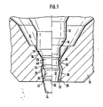
- Figures 1 to 4 each show a partial section through one of the exemplary embodiments.
- valve 1 has a nozzle body 10, in which a valve needle 12 is guided radially and is axially displaceably mounted.
- a pressure chamber 14 is formed in the nozzle body 10, into which the fuel is introduced and which has a valve seat 16 on the bottom, against which a sealing cone 18 of the valve needle 12 is pressed by a closing spring (not shown).
- the valve seat 16 is followed by a nozzle bore 20, at the mouth of which an ejection opening 22 is formed.
- a throttle pin 24 engages in the nozzle bore 20, which connects to the sealing cone 18 of the valve needle 12 and is connected in one piece to it. From the sealing cone 18, the throttle pin 24 has a first cylindrical pin portion 26, which merges conically at a control edge 28 into a pin portion 30 with a smaller diameter. This passes over a conical intermediate area into a further cylindrical pin section 32, whose diameter corresponds approximately to that of the pin section 26. An injection molding extension 34 of the throttle pin is connected to the pin section 32.
- the nozzle bore 20 has a first cylindrical wall portion 35, the diameter of which is larger than the diameter of the pin portion 26 by twice the width of a desired annular gap between the pin portion 26 and the nozzle bore.
- the cylindrical bore section 35 is adjoined by a bore section 36 which initially increases in diameter and then decreases again, which at the ejection opening 22 merges into a cylindrical bore section 38, the diameter of which corresponds to that of the bore section 35.
- the largest diameter of the middle bore section 36 is larger by approximately the difference in diameter between the bore section 35 and the pin section 30 than the pin section 32.
- the position of the largest diameter of the middle bore section 36 is chosen such that it is with the valve needle 12 fully raised (right half Figure 1) is located approximately at the height of the pin portion 32.
- the control edge 28 occurs Za pfenabrough out of the bore portion 35 of the nozzle bore 26; after which the reduced-diameter pin section 30 releases a larger annular gap between the nozzle bore and throttle pin, through which the main jet of fuel is able to pass practically unthrottled.
- its pin section 32 also comes out of the area of the throttle point 42, the cross section of the nozzle bore continuously expanding at this point and the throttling effect being dissolved.
- the pin portion 32 has entered the area of the largest diameter of the central bore portion 36, so that a through the entire nozzle bore sufficiently large annular gap for unthrottled flow of fuel results.
- a nozzle bore 44 has a first cylindrical section 46 which merges via a conical section 48 into a second cylindrical section 50 with a smaller diameter.
- the cylindrical section 46 is formed by a smooth bore in a nozzle body 52, which leads from a pressure chamber 54 in the nozzle body to an end face of the nozzle body.
- the two other bore sections 48 and 50 of the nozzle bore 44 run in a molding plate 56 which is fastened to the end face of the nozzle body 52, centered by a projection projecting into the bore 46.
- a throttle pin 58 of a valve needle 60 projects into the nozzle bore 44 and is shaped such that it forms two throttle gaps 62 and 64 in the nozzle bore in the illustrated closed position of the valve needle 60 and delimits them radially inwards.
- the throttle pin 60 has a first cylindrical section 66 which merges via a conical section 68 into a second cylindrical section 70 of smaller diameter, on which an injection molding pin 72 is scheduled.
- the diameter of the cylindrical pin section 66 is listed to be twice the width of the desired throttle gap 62 smaller than the diameter of the bore section 46.
- the diameter of the pin section 70 is matched in the same way with respect to the bore section 50.
- the throttle gap 64 is in front of the throttle gap 62 serving for metering fuel, so that it cannot be impaired by deposits from the combustion gases.
- the throttle gap 64 is omitted, so that both the pre-jet and the subsequent main jet of the fuel can spray freely.
- nozzle body 74 in which a valve needle provided with a sealing cone 76 is guided radially and is axially displaceably mounted.
- the sealing cone 76 cooperates with a conical valve seat 78 at the lower end of a pressure space for the fuel, not shown in the drawing.
- a cylindrical throttle pin 80 adjoins the sealing cone 76, which plunges with a certain radial play into a throttle bore 82 in the nozzle body, which adjoins the valve seat 78 downstream.
- the throttle pin 80 is provided with a transverse bore 84 which traverses a longitudinal bore 86 which opens out on the free end face 88 of the throttle pin 80.
- the throttle pin 80 is provided with an annular groove 96 in its circumferential surface, in the area of which the transverse bore 84 opens out at both ends.
- two pin sections 98 and 100 are defined, which are separated from one another and are dimensioned in terms of their length, one of which, 98, the throttle gap 90 and the other, 100, delimits an additional throttle gap 102.
- the additional throttle gap 102 which can be the same, smaller or larger than the throttle gap 90, is arranged in front of the throttle gap 90 serving for fuel metering as protection against combustion gases and remains effective over the entire stroke range of the valve needle. A clogging of the additional throttle gap 102 by combustion residues is irrelevant for the proper functioning of the valve needle.
- the construction and the mode of operation of the injection nozzle according to FIG. 4 largely correspond to the injection nozzle according to FIG. 3. However, it has a throttle pin 104 with an additional, transverse bore 106 and an additional longitudinal bore 108, the cross section of which is matched to the idling quantity (pre-jet), similar to a perforated pin nozzle.
- the injection quantity is determined and injected at idle via the longitudinal bore 108 and at full load via the larger longitudinal bore 86.
- the additional throttle gap 102 remains effective in the entire operating range.
Landscapes
- Engineering & Computer Science (AREA)
- Chemical & Material Sciences (AREA)
- Combustion & Propulsion (AREA)
- Mechanical Engineering (AREA)
- General Engineering & Computer Science (AREA)
- Fuel-Injection Apparatus (AREA)
Applications Claiming Priority (2)
| Application Number | Priority Date | Filing Date | Title |
|---|---|---|---|
| DE19813112467 DE3112467A1 (de) | 1981-03-28 | 1981-03-28 | "kraftstoff-einspritzduese fuer brennkraftmaschinen" |
| DE3112467 | 1981-03-28 |
Publications (2)
| Publication Number | Publication Date |
|---|---|
| EP0061529A1 true EP0061529A1 (fr) | 1982-10-06 |
| EP0061529B1 EP0061529B1 (fr) | 1985-06-19 |
Family
ID=6128671
Family Applications (1)
| Application Number | Title | Priority Date | Filing Date |
|---|---|---|---|
| EP81109692A Expired EP0061529B1 (fr) | 1981-03-28 | 1981-11-14 | Buse d'injection de carburant pour moteurs à combustion interne |
Country Status (3)
| Country | Link |
|---|---|
| EP (1) | EP0061529B1 (fr) |
| JP (1) | JPS57173556A (fr) |
| DE (2) | DE3112467A1 (fr) |
Cited By (2)
| Publication number | Priority date | Publication date | Assignee | Title |
|---|---|---|---|---|
| GB2143274A (en) * | 1983-07-12 | 1985-02-06 | Lucas Ind Plc | Fuel injection nozzle |
| KR100722012B1 (ko) * | 1999-06-03 | 2007-05-25 | 코닌클리즈케 필립스 일렉트로닉스 엔.브이. | 반도체 디바이스 |
Citations (4)
| Publication number | Priority date | Publication date | Assignee | Title |
|---|---|---|---|---|
| FR886596A (fr) * | 1941-10-08 | 1943-10-19 | Bosch Gmbh Robert | Soupape d'injection pour moteurs à combustion interne |
| GB562033A (en) * | 1942-11-11 | 1944-06-15 | William Reginald Cobb | Improvements relating to fuel injectors for internal combustion engines |
| GB950252A (en) * | 1961-02-18 | 1964-02-26 | Bosch Gmbh Robert | Improvements in fuel injection valves for internal combustion engines |
| DE2710003A1 (de) * | 1977-03-08 | 1978-09-14 | Bosch Gmbh Robert | Kraftstoffeinspritzduese |
Family Cites Families (1)
| Publication number | Priority date | Publication date | Assignee | Title |
|---|---|---|---|---|
| JPS559837B2 (fr) * | 1973-04-26 | 1980-03-12 |
-
1981
- 1981-03-28 DE DE19813112467 patent/DE3112467A1/de not_active Withdrawn
- 1981-11-14 DE DE8181109692T patent/DE3171063D1/de not_active Expired
- 1981-11-14 EP EP81109692A patent/EP0061529B1/fr not_active Expired
-
1982
- 1982-03-29 JP JP57049235A patent/JPS57173556A/ja active Pending
Patent Citations (4)
| Publication number | Priority date | Publication date | Assignee | Title |
|---|---|---|---|---|
| FR886596A (fr) * | 1941-10-08 | 1943-10-19 | Bosch Gmbh Robert | Soupape d'injection pour moteurs à combustion interne |
| GB562033A (en) * | 1942-11-11 | 1944-06-15 | William Reginald Cobb | Improvements relating to fuel injectors for internal combustion engines |
| GB950252A (en) * | 1961-02-18 | 1964-02-26 | Bosch Gmbh Robert | Improvements in fuel injection valves for internal combustion engines |
| DE2710003A1 (de) * | 1977-03-08 | 1978-09-14 | Bosch Gmbh Robert | Kraftstoffeinspritzduese |
Cited By (3)
| Publication number | Priority date | Publication date | Assignee | Title |
|---|---|---|---|---|
| GB2143274A (en) * | 1983-07-12 | 1985-02-06 | Lucas Ind Plc | Fuel injection nozzle |
| GB2185070A (en) * | 1983-07-12 | 1987-07-08 | Lucas Ind Plc | Fuel injection nozzle |
| KR100722012B1 (ko) * | 1999-06-03 | 2007-05-25 | 코닌클리즈케 필립스 일렉트로닉스 엔.브이. | 반도체 디바이스 |
Also Published As
| Publication number | Publication date |
|---|---|
| DE3112467A1 (de) | 1982-12-30 |
| JPS57173556A (en) | 1982-10-25 |
| DE3171063D1 (en) | 1985-07-25 |
| EP0061529B1 (fr) | 1985-06-19 |
Similar Documents
| Publication | Publication Date | Title |
|---|---|---|
| EP0980474B1 (fr) | Injecteur de carburant pour moteurs a combustion interne a auto-allumage | |
| EP1076772B1 (fr) | Injecteur de carburant pour moteur a combustion interne | |
| DE2710138A1 (de) | Mehrloch-einspritzduese | |
| EP1163442B1 (fr) | Injecteur de carburant | |
| DE2658783C2 (de) | Luftverdichtende, direkt einspritzende Brennkraftmaschine | |
| DE2750929A1 (de) | Kraftstoff-einspritzduese fuer brennkraftmaschinen | |
| DE68904172T2 (de) | Kraftstoffeinspritzduese. | |
| DE2833431A1 (de) | Kraftstoffeinspritzduese | |
| EP1387950B1 (fr) | Soupape dotee de cavites radiales | |
| EP0064146A1 (fr) | Système d'injection pour injecter deux combustibles par une seule buse d'injection | |
| EP1117928B1 (fr) | Buse d'injection de carburant | |
| DE3544503A1 (de) | Spaltfilter fuer eine einspritzduese | |
| EP1346143A1 (fr) | Soupape d'injection de carburant destinee a des moteurs a combustion interne | |
| EP0223018B1 (fr) | Soupape électromagnétique de combustion | |
| DE4415992A1 (de) | Brennstoffeinspritzventil | |
| EP1312789B1 (fr) | Injecteur de carburant à double source | |
| DE3734587A1 (de) | Kraftstoff-einspritzduese fuer brennkraftmaschinen | |
| DE4437927A1 (de) | Injektor mit Magnetventilsteuerung zur Kraftstoffeinspritzung in den Brennraum einer Dieselbrennkraftmaschine | |
| DE3818862A1 (de) | Kraftstoffeinspritzduese | |
| DD139739A1 (de) | Kraftstoff-einspritzduese | |
| EP0061529A1 (fr) | Buse d'injection de carburant pour moteurs à combustion interne | |
| EP0083001A1 (fr) | Système d'injection de combustible pour l'injection directe de combustible dans les moteurs à combustion interne | |
| AT397289B (de) | Kraftstoffeinspritzdüse für brennkraftmaschinen | |
| DE4413937C2 (de) | Kraftstoffeinspritzventil | |
| DE10208222A1 (de) | Brennstoffeinspritzventil |
Legal Events
| Date | Code | Title | Description |
|---|---|---|---|
| PUAI | Public reference made under article 153(3) epc to a published international application that has entered the european phase |
Free format text: ORIGINAL CODE: 0009012 |
|
| 17P | Request for examination filed |
Effective date: 19811114 |
|
| AK | Designated contracting states |
Designated state(s): DE FR GB IT |
|
| ITF | It: translation for a ep patent filed | ||
| GRAA | (expected) grant |
Free format text: ORIGINAL CODE: 0009210 |
|
| AK | Designated contracting states |
Designated state(s): DE FR GB IT |
|
| REF | Corresponds to: |
Ref document number: 3171063 Country of ref document: DE Date of ref document: 19850725 |
|
| ET | Fr: translation filed | ||
| PLBE | No opposition filed within time limit |
Free format text: ORIGINAL CODE: 0009261 |
|
| STAA | Information on the status of an ep patent application or granted ep patent |
Free format text: STATUS: NO OPPOSITION FILED WITHIN TIME LIMIT |
|
| 26N | No opposition filed | ||
| PGFP | Annual fee paid to national office [announced via postgrant information from national office to epo] |
Ref country code: GB Payment date: 19900905 Year of fee payment: 10 |
|
| PGFP | Annual fee paid to national office [announced via postgrant information from national office to epo] |
Ref country code: FR Payment date: 19901129 Year of fee payment: 10 |
|
| ITTA | It: last paid annual fee | ||
| PGFP | Annual fee paid to national office [announced via postgrant information from national office to epo] |
Ref country code: DE Payment date: 19910129 Year of fee payment: 10 |
|
| PG25 | Lapsed in a contracting state [announced via postgrant information from national office to epo] |
Ref country code: GB Effective date: 19911114 |
|
| GBPC | Gb: european patent ceased through non-payment of renewal fee | ||
| PG25 | Lapsed in a contracting state [announced via postgrant information from national office to epo] |
Ref country code: FR Effective date: 19920731 |
|
| PG25 | Lapsed in a contracting state [announced via postgrant information from national office to epo] |
Ref country code: DE Effective date: 19920801 |
|
| REG | Reference to a national code |
Ref country code: FR Ref legal event code: ST |