EP0061539B1 - Verfahren der Regelung für ein mehradriges Walzwerk - Google Patents
Verfahren der Regelung für ein mehradriges Walzwerk Download PDFInfo
- Publication number
- EP0061539B1 EP0061539B1 EP19810301316 EP81301316A EP0061539B1 EP 0061539 B1 EP0061539 B1 EP 0061539B1 EP 19810301316 EP19810301316 EP 19810301316 EP 81301316 A EP81301316 A EP 81301316A EP 0061539 B1 EP0061539 B1 EP 0061539B1
- Authority
- EP
- European Patent Office
- Prior art keywords
- roll
- strand
- roll stand
- strands
- rolling
- Prior art date
- Legal status (The legal status is an assumption and is not a legal conclusion. Google has not performed a legal analysis and makes no representation as to the accuracy of the status listed.)
- Expired
Links
Images

Classifications
-
- B—PERFORMING OPERATIONS; TRANSPORTING
- B21—MECHANICAL METAL-WORKING WITHOUT ESSENTIALLY REMOVING MATERIAL; PUNCHING METAL
- B21B—ROLLING OF METAL
- B21B37/00—Control devices or methods specially adapted for metal-rolling mills or the work produced thereby
- B21B37/16—Control of thickness, width, diameter or other transverse dimensions
- B21B37/165—Control of thickness, width, diameter or other transverse dimensions responsive mainly to the measured thickness of the product
-
- B—PERFORMING OPERATIONS; TRANSPORTING
- B21—MECHANICAL METAL-WORKING WITHOUT ESSENTIALLY REMOVING MATERIAL; PUNCHING METAL
- B21B—ROLLING OF METAL
- B21B1/00—Metal-rolling methods or mills for making semi-finished products of solid or profiled cross-section; Sequence of operations in milling trains; Layout of rolling-mill plant, e.g. grouping of stands; Succession of passes or of sectional pass alternations
- B21B1/16—Metal-rolling methods or mills for making semi-finished products of solid or profiled cross-section; Sequence of operations in milling trains; Layout of rolling-mill plant, e.g. grouping of stands; Succession of passes or of sectional pass alternations for rolling wire rods, bars, merchant bars, rounds wire or material of like small cross-section
- B21B1/18—Metal-rolling methods or mills for making semi-finished products of solid or profiled cross-section; Sequence of operations in milling trains; Layout of rolling-mill plant, e.g. grouping of stands; Succession of passes or of sectional pass alternations for rolling wire rods, bars, merchant bars, rounds wire or material of like small cross-section in a continuous process
-
- B—PERFORMING OPERATIONS; TRANSPORTING
- B21—MECHANICAL METAL-WORKING WITHOUT ESSENTIALLY REMOVING MATERIAL; PUNCHING METAL
- B21B—ROLLING OF METAL
- B21B13/00—Metal-rolling stands, i.e. an assembly composed of a stand frame, rolls, and accessories
- B21B13/02—Metal-rolling stands, i.e. an assembly composed of a stand frame, rolls, and accessories with axes of rolls arranged horizontally
-
- B—PERFORMING OPERATIONS; TRANSPORTING
- B21—MECHANICAL METAL-WORKING WITHOUT ESSENTIALLY REMOVING MATERIAL; PUNCHING METAL
- B21B—ROLLING OF METAL
- B21B13/00—Metal-rolling stands, i.e. an assembly composed of a stand frame, rolls, and accessories
- B21B2013/006—Multiple strand rolling mills; Mill stands with multiple caliber rolls
Definitions
- This invention relates to a method of controlling a multistrand rolling mill of the kind comprising a plurality of roll stands disposed in tandem to roll simultaneously a plurality of strands, in which method the trailing end and the leading end of each of a plurality of strands are traced, and each time at least one strand end passes through each of the roll stands, the ratio of the rolling speeds of the stands is adjusted.
- a method is disclosed in DE-C-1 143263.
- FIG. 1 of the accompanying drawings there is illustrated the essential portion of a roll stand for rolling a pair of workpiece strands simultaneously.
- the arrangement illustrated comprises a pair of upper and lower working rolls 10 and 12 arranged one above the other to form a roll gap therebetween.
- Each of the upper and lower rolls 10 and 12 includes a plurality of axially spaced forming grooves, in this case, two grooves extending circumferentially around the entire surface thereof opposite those on the other rbll.
- Each of the opposed pair of grooves has a cross section substantially complementary to that of a workpiece strand to be rolled.
- FIG. 1 a pair of workpiece strands 14 and 16 are shown in cross section as being sandwiched between the opposite forming grooves on the upper and lower rolls 10 and 12 respectively with a small spacing therebetween.
- the lower roll 12 includes a pair of shafts protruding from both sides thereof and extending rotatably through the opposite lateral walls of a housing 18.
- the upper roll 10 includes a pair of similar shafts extending not only rotatably but also movable toward and away from the lower roll 12 under the control of screw-down devices 20 and 22 disposed in the upper portions of the opposite walls of the housing 18 on the working and driving sides respectively.
- the screw-down devices may be of the electrically operated type or the oil pressure type but they are generally of the manually operated type with rolling mills rolling a plurality of strands simultaneously.
- the roll gap between the upper and lower rolls 10 and 12 is variable in accordance with their loading. Under no load i.e. in the absence of the workpieces, the upper and lower rolls 10 and 12 respectively are located at a roll separation So equal to a magnitude determined by the particular rolling schedule. The lower roll 12 is fixed in its position.
- the upper roll 10 can be tilted.
- the rolling speed on each roll stand arranged in a tandem arrangement in a rolling mill has been preliminarily set to a magnitude determined by a rolling pass schedule and a pair of screw-down devices on each side of each roll stand have been manually operated to set a roll gap between the mating upper and lower working rolls to the magnitude determined by that schedule.
- each workpiece path along which the strands travel may include a gap between the trailing end of one strand and the leading end of the next.
- the roll stand as shown in Figure 1 may change from its state in which both the strands 14 and 16 are being simultaneously rolled to the state in which only one of these strands is being rolled.
- F w and F D designate the rolling force for the strand 14 on the working side and that for the strand 16 on the driving side respectively.
- screwing-down forces F wso and Foso are generated, as reactions to those rolling forces, at screw-down positions on the working and driving sides respectively and
- a plurality of roll stands are disposed in tandem i.e. one after the other to roll simultaneously, for example, a pair of strands and are followed by a pair of branched arrays of roll stands disposed in tandem one for each workpiece each to roll only the associated workpiece.
- Each of the roll stands for rolling simultaneously the pair of strand workpieces includes a pair of upper and lower working rolls as described above and each of the roll stands in the branched arrays includes a pair of upper and lower working rolls differing from those described above only in that in the former stand a single forming groove is disposed on each working roll.
- the present invention seeks to provide a method of controlling a multi-strand rolling mill comprising a plurality of roll stands disposed in tandem so that, when at least one of a plurality of strands leaves or enters any one of the roll stands rolling simultaneously the strands, constant mass flow of the strands is maintained throughout the rolling mills.
- the present invention provides a method of controlling a multi-strand rolling mill comprising a plurality of roll stands disposed in tandem to roll simultaneously a plurality of strands, comprising the steps of tracing the trailing end and the leading end of each of a plurality of strands, and each time at least one strand end passes through each of the roll stands adjusting the ratio of the rolling speeds of the roll stands, characterised in that the ratios of the rolling speed of the roll stand(s) upstream of the roll stand through which the said strand end passes, the rolling speed of the last-mentioned roll stand, and the rolling speed of the roll stand(s) downstream of the latter roll stand are given by: wherein b, and f, designate the rate of backward slip and the rate of forward slip on the roll stand through which the said strand end passes, when all the strands are present in the last-mentioned roll stand, and b 2 and f 2 designate the rate of backward slip and the rate of forward slip on the same roll stand when
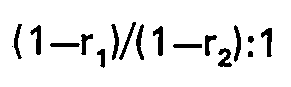
- the present invention provides a method of controlling a multi-strand rolling mill comprising a plurality of roll stands disposed in tandem to roll simultaneously a plurality of strands, comprising the steps of tracing the trailing end and the leading end of each of a plurality of strands, and each time at least one strand end passes through each of the roll stands adjusting the ratio of the rolling speeds of the roll stands, characterised in that the ratio of the rolling speed of the roll stand(s) upstream of roll stand through which the said strand end passes and the rolling speed of the last-mentioned roll stand is: while the rolling speed downstream of the last-mentioned stand remains unchanged, wherein r, designates the screw-down rate on the roll stand through which the said strand end has passed, when all the strands are present in the last-mentioned roll stand, and r 2 designates the screw-down rate on the same roll stand when the end of the strand has passed through the said roll stand.
- the present invention provides a method of controlling a multi-strand rolling mill comprising a plurality of roll stands disposed in tandem to roll simultaneously a plurality of strands, comprising the steps of tracing the trailing end and the leading end of each of a plurality of strands, and each time at least one strand end passes through each of the roll stands adjusting the ratio of the rolling speeds of the roll stands, characterised in that the ratio of the rolling speed of the roll stand through which the strand end passes, and the rolling speed of the roll stand(s) downstream of the latter roll stand is while the rolling speed upstream of the last-mentioned roll stand remains unchanged, wherein r 1 designates the screw-down rate on the roll stand through which the strand end has passed, when all the strands are present in the last-mentioned roll stand, and r 2 designates the screw-down rate on the same roll stand when the strand has passed through the said roll stand.
- Figure 2 shows the manner in which the arrangement of Figure 1 rolls the strands 16.
- the roll gap at the position of the strands 16 is determined by the upper and lower roll now designated by an upper and lower dotted circle 32 and 34 respectively.
- the workpiece 16 enters at an entry speed V El into that roll gap and is rolled into a strand 36. Then the rolled strand 36 leaves with a delivery speed V DI the roll opening.
- the roll gap at the position of the strand 16 is determined by the roll gap between the upper and the lower roll designated by the upper and lower solid circle 38 and 40 respectively.
- the strand 16 enters at an entry speed V E2 into that roll opening and is rolled into a strand 42. Then the rolled strand 42 leaves the roll gap at a delivery speed Vp 2 .
- the upper and lower working rolls have a common speed of rotation remaining unchanged regardless of whether or not a workpiece 14 is present between the working rolls.
- the rolled strand 42 has a ratio of its delivery speed to the circumferential speed of the roll (which is called hereinafter the rate of forward slip) larger than that of the rolled strand 36 because the rolls have screwed down the strand 42 more than the strand 36. Therefore at the outgoing side of the rolls the strand 36 travels at a lower speed than the strand 42. That is, V D1 ⁇ V D2 holds.
- the entry speed V EI is higher than that V E2 due to the change in rate of backward slip which implies a ratio of the entry speed of the strand to the circumferential speed of the working roll.
- Figure 3 shows a multi-strand rolling mill.
- the arrangement illustrated comprises a pair of roll stands 44 and 46 disposed in tandem to roll a pair of working piece strand, A and B simultaneously and a pair of branched arrays each including two roll stands 48 and 50 or 49 and 51 disposed in tandem to roll only an associated one of the strands A or B.
- the workpiece A is being rolled on the roll stands 44, 46, 48 and 50 while it travels along loops 52 and 54 between the roll stands 46 and 48 and between the roll stands 48 and 50 respectively.
- the workpiece A leaves the roll stand 50 as shown by the arrow 56 in Figure 3.
- the strand B is shown in Figure 3 as having just left the roll stand 46 and forming similar loops 53 and 55 between the roll stands 46 and 49 and between the roll stands 49 and 51 respectively. Then the workpiece B leaves the roll stand 51 as shown at the arrow 56 in Figure 3.
- the roll stands 44, 46, 48, 49, 50 and 51 have respectively rolling speeds or speeds of the rolls as determined so that each of the roll stands is equal in mass flow in unit time of the workpiece A or B to other roll stands.
- the workpiece B has already left the roll stand 46 and therefore the delivery speed of the strand workpiece A increases to V 12 from V D1 while at the same time the entry speed thereof decreases to V E2 from V E1 as described above in conjunction with Figure 2.
- the strand A has a mass flow which is not kept constant throughout the arrangement of Figure 3.
- the present invention allows a constant mass flow to be maintained throughout a multi- strand rolling mill comprising a plurality of roll stands disposed in tandem to roll simultaneously a plurality of strand workpiece even when at least one of the strand workpieces leaves or enters one of the roll stands.
- each of the manual screw-down devices 20 or 22 as shown in Figure 1 is replaced by a remotely actuatable, fast response screw-down device such as an electrically operated or an oil pressure screw-down device and there is provided tracing means for tracing the position of the leading and trailing end of each of the workpiece strands.
- a remotely actuatable, fast response screw-down device such as an electrically operated or an oil pressure screw-down device and there is provided tracing means for tracing the position of the leading and trailing end of each of the workpiece strands.
- each of the upper and lower rolls is rotated at a constant circumferential speed or a constant rolling speed V R and each of the plurality of strands has an entry speed V E1 and a delivery speed V D1 with the large roll gap or in the presence of all the strand workpieces on the rolls as well as an entry speed V 12 and a delivery speed V D2 with the small roll gap or in the absence of at least one strand workpieces on the rolls as described above.
- the measure to change the rolling speed on each of all the upstream roll stands alone is arranged to maintain the speeds on all the downstream roll stands constant although those speeds should actually change by a factor as defined by the expression (10). From this it will readily be understood that it is required only to multiply the speeds on all the upstream roll stands including the roll stand 46 by the reciprocal of the factor defined by the expression (10). Thus it is concluded that it is sufficient to multiply the speed on the roll stand 46 by a factor (1 +f 1 )/(1+f 2 ) while at the same time multiplying the speeds on the roll stands disposed upstream of the roll stand 46 by a factor expressed by
- the present invention has been illustrated and described in conjunction with a control method comprising steps of tracing the trailing and leading end of each of the strands, sensing the trailing or leading end of either one thereof leaving or entering one of roll stands and changing the speed ratios of the roll stands disposed upstream or downstream of that roll stand or all the roll stands simultaneously with the sensing of the associated workpiece, it is to be understood that it is essential to change the rolling entry, delivery speeds on the roll stands upstream of that roll stand changed in number of strand workpieces being roll, and last-mentioned roll stand and those downstream thereof following a speed ratio
- the present invention has been described in conjunction with ratios with which the rolling speeds are changed on the respective roll stands, but it is noted that at least one of the strands does not leave or enter the roll stand instantaneously but that it leaves or enters the roll stand within a constant time interval as determined by the speeds thereof, the diameter of the working rolls and screwdown rate on that roll stand. As a result, it has been found that the more satisfactory result is given by making substantially equal the time interval over which the speeds are changed to the constant time interval as described above.
Landscapes
- Engineering & Computer Science (AREA)
- Mechanical Engineering (AREA)
- Metal Rolling (AREA)
- Control Of Metal Rolling (AREA)
Claims (3)


Priority Applications (2)
| Application Number | Priority Date | Filing Date | Title |
|---|---|---|---|
| DE8181301316T DE3168723D1 (en) | 1981-03-26 | 1981-03-26 | Control method for multi-strand rolling mill |
| EP19810301316 EP0061539B1 (de) | 1981-03-26 | 1981-03-26 | Verfahren der Regelung für ein mehradriges Walzwerk |
Applications Claiming Priority (1)
| Application Number | Priority Date | Filing Date | Title |
|---|---|---|---|
| EP19810301316 EP0061539B1 (de) | 1981-03-26 | 1981-03-26 | Verfahren der Regelung für ein mehradriges Walzwerk |
Publications (2)
| Publication Number | Publication Date |
|---|---|
| EP0061539A1 EP0061539A1 (de) | 1982-10-06 |
| EP0061539B1 true EP0061539B1 (de) | 1985-02-06 |
Family
ID=8188251
Family Applications (1)
| Application Number | Title | Priority Date | Filing Date |
|---|---|---|---|
| EP19810301316 Expired EP0061539B1 (de) | 1981-03-26 | 1981-03-26 | Verfahren der Regelung für ein mehradriges Walzwerk |
Country Status (2)
| Country | Link |
|---|---|
| EP (1) | EP0061539B1 (de) |
| DE (1) | DE3168723D1 (de) |
Families Citing this family (2)
| Publication number | Priority date | Publication date | Assignee | Title |
|---|---|---|---|---|
| CN103658193B (zh) * | 2012-08-30 | 2015-09-23 | 宝山钢铁股份有限公司 | 交叉布置式两辊连轧机架孔型抬高方法 |
| EP3507029A4 (de) | 2016-08-30 | 2020-01-15 | Schmacker Investments PTY Ltd | Drahtelement und verfahren zur herstellung eines drahtelements |
Family Cites Families (2)
| Publication number | Priority date | Publication date | Assignee | Title |
|---|---|---|---|---|
| US2933956A (en) * | 1958-01-30 | 1960-04-26 | United States Steel Corp | Automatic screwdown-control system for rod mill |
| US3251207A (en) * | 1963-03-08 | 1966-05-17 | Morgan Construction Co | Automatic screwdown control |
-
1981
- 1981-03-26 EP EP19810301316 patent/EP0061539B1/de not_active Expired
- 1981-03-26 DE DE8181301316T patent/DE3168723D1/de not_active Expired
Also Published As
| Publication number | Publication date |
|---|---|
| DE3168723D1 (en) | 1985-03-21 |
| EP0061539A1 (de) | 1982-10-06 |
Similar Documents
| Publication | Publication Date | Title |
|---|---|---|
| DE102010014350B4 (de) | Walzstraße, Walzvorrichtung und Steuerverfahren dafür | |
| DE3907905C2 (de) | Stranggießverfahren | |
| US4864836A (en) | Rolling method making use of work roll shift rolling mill | |
| US4457154A (en) | Control method for multi-strand rolling mill | |
| US3709017A (en) | Method of rolling metal sheet articles between the driven rolls of the roll mill | |
| DE2645497C2 (de) | ||
| EP3253505B1 (de) | Verfahren und vorrichtung zum prägewalzen eines bandes | |
| US4193283A (en) | Method of slitting a double or triple stranded bar | |
| EP0224333A2 (de) | Presse zur Verringerung der Breite von warmen Brammen | |
| EP0205701B1 (de) | Kontinuierliches Walzverfahren | |
| DE69904513T2 (de) | Verfahren zum Steuern einer kontinuierlichen Kaltverformung eines Metallbands | |
| EP0061539B1 (de) | Verfahren der Regelung für ein mehradriges Walzwerk | |
| US6050122A (en) | Slitter for the production of multiple sections | |
| DE69623343T2 (de) | Walzwerk, walzverfahren und walzanlage | |
| EP1784266B1 (de) | Walzwerk zum walzen von metallischem band | |
| AU660552B2 (en) | Finishing block with dual speed sizing capability | |
| EP3437748A1 (de) | Massenflussregelung in walzanlagen | |
| EP0109235B1 (de) | Walzwerksteuerung für Tandem-Walzen | |
| GB1569196A (en) | Slitting a multi-stranded bar | |
| EP1786577B1 (de) | Verfahren zum walzen eines metallbands | |
| DE10159608B9 (de) | Walzverfahren und Walzstraße für ein Band mit einer Schweißnaht | |
| EP1669141B1 (de) | Verfahren zur Regelung des Querschnitts von aus einer Drahtwalzstrasse austretenden Drähten und Drahtwalzstrasse | |
| GB2078581A (en) | Continuous hot rolling | |
| JPS63168201A (ja) | H形鋼の粗ユニバ−サル圧延機 | |
| JPH0616890B2 (ja) | 圧延材板形状の調整装置 |
Legal Events
| Date | Code | Title | Description |
|---|---|---|---|
| PUAI | Public reference made under article 153(3) epc to a published international application that has entered the european phase |
Free format text: ORIGINAL CODE: 0009012 |
|
| 17P | Request for examination filed |
Effective date: 19811029 |
|
| AK | Designated contracting states |
Designated state(s): DE FR GB |
|
| GRAA | (expected) grant |
Free format text: ORIGINAL CODE: 0009210 |
|
| AK | Designated contracting states |
Designated state(s): DE FR GB |
|
| REF | Corresponds to: |
Ref document number: 3168723 Country of ref document: DE Date of ref document: 19850321 |
|
| ET | Fr: translation filed | ||
| PLBE | No opposition filed within time limit |
Free format text: ORIGINAL CODE: 0009261 |
|
| STAA | Information on the status of an ep patent application or granted ep patent |
Free format text: STATUS: NO OPPOSITION FILED WITHIN TIME LIMIT |
|
| 26N | No opposition filed | ||
| PGFP | Annual fee paid to national office [announced via postgrant information from national office to epo] |
Ref country code: FR Payment date: 19930309 Year of fee payment: 13 |
|
| PGFP | Annual fee paid to national office [announced via postgrant information from national office to epo] |
Ref country code: GB Payment date: 19930312 Year of fee payment: 13 |
|
| PGFP | Annual fee paid to national office [announced via postgrant information from national office to epo] |
Ref country code: DE Payment date: 19930324 Year of fee payment: 13 |
|
| PG25 | Lapsed in a contracting state [announced via postgrant information from national office to epo] |
Ref country code: GB Effective date: 19940326 |
|
| GBPC | Gb: european patent ceased through non-payment of renewal fee |
Effective date: 19940326 |
|
| PG25 | Lapsed in a contracting state [announced via postgrant information from national office to epo] |
Ref country code: FR Effective date: 19941130 |
|
| PG25 | Lapsed in a contracting state [announced via postgrant information from national office to epo] |
Ref country code: DE Effective date: 19941201 |
|
| REG | Reference to a national code |
Ref country code: FR Ref legal event code: ST |