EP0061543A1 - Bremssteuereinrichtung für Kraftfahrzeuge - Google Patents
Bremssteuereinrichtung für Kraftfahrzeuge Download PDFInfo
- Publication number
- EP0061543A1 EP0061543A1 EP81301344A EP81301344A EP0061543A1 EP 0061543 A1 EP0061543 A1 EP 0061543A1 EP 81301344 A EP81301344 A EP 81301344A EP 81301344 A EP81301344 A EP 81301344A EP 0061543 A1 EP0061543 A1 EP 0061543A1
- Authority
- EP
- European Patent Office
- Prior art keywords
- conduit
- fluid
- vehicle
- operable
- control means
- Prior art date
- Legal status (The legal status is an assumption and is not a legal conclusion. Google has not performed a legal analysis and makes no representation as to the accuracy of the status listed.)
- Granted
Links
- 239000012530 fluid Substances 0.000 claims description 23
- 230000002401 inhibitory effect Effects 0.000 claims description 10
- 230000007935 neutral effect Effects 0.000 description 3
- 230000000694 effects Effects 0.000 description 1
- 239000007788 liquid Substances 0.000 description 1
- 238000000034 method Methods 0.000 description 1
- 238000011144 upstream manufacturing Methods 0.000 description 1
Images
Classifications
-
- B—PERFORMING OPERATIONS; TRANSPORTING
- B60—VEHICLES IN GENERAL
- B60T—VEHICLE BRAKE CONTROL SYSTEMS OR PARTS THEREOF; BRAKE CONTROL SYSTEMS OR PARTS THEREOF, IN GENERAL; ARRANGEMENT OF BRAKING ELEMENTS ON VEHICLES IN GENERAL; PORTABLE DEVICES FOR PREVENTING UNWANTED MOVEMENT OF VEHICLES; VEHICLE MODIFICATIONS TO FACILITATE COOLING OF BRAKES
- B60T13/00—Transmitting braking action from initiating means to ultimate brake actuator with power assistance or drive; Brake systems incorporating such transmitting means, e.g. air-pressure brake systems
- B60T13/10—Transmitting braking action from initiating means to ultimate brake actuator with power assistance or drive; Brake systems incorporating such transmitting means, e.g. air-pressure brake systems with fluid assistance, drive, or release
- B60T13/24—Transmitting braking action from initiating means to ultimate brake actuator with power assistance or drive; Brake systems incorporating such transmitting means, e.g. air-pressure brake systems with fluid assistance, drive, or release the fluid being gaseous
- B60T13/26—Compressed-air systems
- B60T13/268—Compressed-air systems using accumulators or reservoirs
-
- B—PERFORMING OPERATIONS; TRANSPORTING
- B60—VEHICLES IN GENERAL
- B60T—VEHICLE BRAKE CONTROL SYSTEMS OR PARTS THEREOF; BRAKE CONTROL SYSTEMS OR PARTS THEREOF, IN GENERAL; ARRANGEMENT OF BRAKING ELEMENTS ON VEHICLES IN GENERAL; PORTABLE DEVICES FOR PREVENTING UNWANTED MOVEMENT OF VEHICLES; VEHICLE MODIFICATIONS TO FACILITATE COOLING OF BRAKES
- B60T11/00—Transmitting braking action from initiating means to ultimate brake actuator without power assistance or drive or where such assistance or drive is irrelevant
- B60T11/10—Transmitting braking action from initiating means to ultimate brake actuator without power assistance or drive or where such assistance or drive is irrelevant transmitting by fluid means, e.g. hydraulic
- B60T11/103—Transmitting braking action from initiating means to ultimate brake actuator without power assistance or drive or where such assistance or drive is irrelevant transmitting by fluid means, e.g. hydraulic in combination with other control devices
-
- B—PERFORMING OPERATIONS; TRANSPORTING
- B60—VEHICLES IN GENERAL
- B60T—VEHICLE BRAKE CONTROL SYSTEMS OR PARTS THEREOF; BRAKE CONTROL SYSTEMS OR PARTS THEREOF, IN GENERAL; ARRANGEMENT OF BRAKING ELEMENTS ON VEHICLES IN GENERAL; PORTABLE DEVICES FOR PREVENTING UNWANTED MOVEMENT OF VEHICLES; VEHICLE MODIFICATIONS TO FACILITATE COOLING OF BRAKES
- B60T15/00—Construction arrangement, or operation of valves incorporated in power brake systems and not covered by groups B60T11/00 or B60T13/00
- B60T15/02—Application and release valves
Definitions
- This invention relates to brake control of motor vehicles.
- Such inhibiting means is generally in the form of a manually operable control member and is provided for safety reasons enabling a driver to operate the control member when a vehicle is to be driven forwardly so that, on operation of the brake system of the vehicle, only the rear brakes are operated thereby avoiding any possibility of the front brakes locking and causing an accident.
- a disadvantage of providing such a control member is that, when a truck is reversing to deposit a load, ground to the rear of the truck is often less firm than ground below the front wheels of the truck and it is desirable to apply front brakes in addition to the rear.brakes to ensure controlled reversal of the truck.
- the disadvantage would be overcome if drivers were to remember to disengage the control member prior to reversal of a truck so that, when the brake system of the truck is operated, the front brakes are operated in addition to the rear brakes, but it has been found that drivers generally fail to do so.
- apparatus for controlling supply of fluid in a brake system of a vehicle comprising a first conduit for supplying the fluid to brake means for a wheel of a vehicle, inhibiting means for inhibiting flow of the fluid in said first conduit, a second conduit for supplying the fluid to the brake means and control means for controlling flow of fluid in said second conduit, the arrangement being such that, when the inhibiting means inhibits flow of the fluid in said first conduit and the control means is operated, the fluid is supplied ⁇ o said brake means through said second conduit.
- 'fluid' includes fluid in a gaseous state or in a liquid state
- the control means may be operable in response to movement of a control member of the vehicle.
- the control means may be operable in response to movement of a gear selection lever of a vehicle.
- the control means may comprise an electrically operable valve member.
- the valve member may be contained in an electrical circuit which also includes a switch operable in response to movement of the lever.
- the switch may be operable when the lever is moved to a position to select reverse gear of the vehicle.
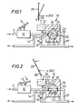
- apparatus 10 for controlling supply of air in an air brake system of a truck (not shown).
- the brake system includes a conduit 11 for supplying air under pressure to front and rear brakes (not shown) of the truck.
- the conduitil isconnected to a valve 12 which is operable by means of a brake pedal 13.
- An outlet of valve 12 is connected to a conduit 14, which directs air from the valve 12 to rear brakes of the truck, and to a conduit 15, which directs air from the valve 12 to front brakes of the truck.
- the conduit 15 includes a manually operable valve 16 arranged, when in an operative position, to inhibit flow of air from the valve 12 to the front brakes of the truck and, when in an inoperative position, to permit flow of air to the front brakes.
- the conduit 15 is provided with an extended portion 17 in communication with the conduit 15 upstream of the valve 16. The extended portion 17 enters into an inlet 18 of a rotary valve 19.
- the valve 19 has an outlet 20 in which is received an end portion of a second extended portion 17' of the conduit 17.
- the second extended portion 17' is in communication with the conduit 17 downstream of the valve 16.
- the rotary valve 19 includes a cylindrical chamber 21 with which the inlet 18 and the outlet 20 are in communication and are located at opposite ends respectively of a diameter of the chamber 21.
- the chamber 21 has located therein a rotary disc member 22 having a passageway 23 extending diametrically therethrough.
- the rotary member 22 is provided with an arcuate gear 24 which engages with a rack 25 provided on an elongate member 26 integral with the armature (not shown) of a solenoid 27.
- the solenoid 27 is connected in an electrical circuit including a switch 28 operable by a gear lever 29 of the truck when the gear lever is moved from a 'neutral' position to a position to select reverse gear of the truck.
- the arrangement is such that, in a de-energised condition of the solenoid 27, the rotary member 22 is located relative to the chamber 21 with the central longitudinal axis of the passageway 23 disposed at an angle to an axis extending through the inlet 18 and the outlet 20 of the valve 19 and, in an energised condition of the solenoid 27, the central longitudinal axis of the passageway 23 is co-axial with the axis extending through the inlet 18 and the outlet 20 of the valve 19.
- valve 16 is by-passed and, when the brake pedal 13 is operated, supply of air is directed not only through the conduit 14 to the rear brakes of the truck but also through the extended portion 17 of the conduit 15., the passageway 23 of the rotary member 22 of the valve 19 and the second extended portion 17' of the conduit 15 to the front brakes of the truck.
- a truck provided with apparatus in accordance with the present invention when reversing to a location at which a load in a skip of the truck is to be deposited, will have air supplied to front brakes thereof on operation of the brake pedal 13 and, in consequence, the front wheels of the truck will be braked. It will be also appreciated that such operation of the front brakes of the truck will be effected even if the driver fails to operate a manually operable valve to permit air of the brake system to be supplied to the front brakes.
Landscapes
- Engineering & Computer Science (AREA)
- Transportation (AREA)
- Mechanical Engineering (AREA)
- Braking Systems And Boosters (AREA)
- Regulating Braking Force (AREA)
- Electric Propulsion And Braking For Vehicles (AREA)
- Control Of Electric Motors In General (AREA)
Priority Applications (4)
| Application Number | Priority Date | Filing Date | Title |
|---|---|---|---|
| US06/247,012 US4623199A (en) | 1981-03-27 | 1981-03-24 | Front brake control |
| DE8181301344T DE3164281D1 (en) | 1981-03-27 | 1981-03-27 | Brake control of motor vehicles |
| AT81301344T ATE8027T1 (de) | 1981-03-27 | 1981-03-27 | Bremssteuereinrichtung fuer kraftfahrzeuge. |
| EP81301344A EP0061543B1 (de) | 1981-03-27 | 1981-03-27 | Bremssteuereinrichtung für Kraftfahrzeuge |
Applications Claiming Priority (1)
| Application Number | Priority Date | Filing Date | Title |
|---|---|---|---|
| EP81301344A EP0061543B1 (de) | 1981-03-27 | 1981-03-27 | Bremssteuereinrichtung für Kraftfahrzeuge |
Publications (2)
| Publication Number | Publication Date |
|---|---|
| EP0061543A1 true EP0061543A1 (de) | 1982-10-06 |
| EP0061543B1 EP0061543B1 (de) | 1984-06-20 |
Family
ID=8188255
Family Applications (1)
| Application Number | Title | Priority Date | Filing Date |
|---|---|---|---|
| EP81301344A Expired EP0061543B1 (de) | 1981-03-27 | 1981-03-27 | Bremssteuereinrichtung für Kraftfahrzeuge |
Country Status (4)
| Country | Link |
|---|---|
| US (1) | US4623199A (de) |
| EP (1) | EP0061543B1 (de) |
| AT (1) | ATE8027T1 (de) |
| DE (1) | DE3164281D1 (de) |
Cited By (1)
| Publication number | Priority date | Publication date | Assignee | Title |
|---|---|---|---|---|
| EP0132462A1 (de) * | 1982-01-22 | 1985-02-13 | Long-Shin Jow | Kraftfahrzeugbremsvorrichtung |
Families Citing this family (1)
| Publication number | Priority date | Publication date | Assignee | Title |
|---|---|---|---|---|
| JPH0220133Y2 (de) * | 1985-05-17 | 1990-06-01 |
Citations (3)
| Publication number | Priority date | Publication date | Assignee | Title |
|---|---|---|---|---|
| US3592315A (en) * | 1969-11-20 | 1971-07-13 | Henry B Lewis | Tractor-trailer brake system |
| US3893698A (en) * | 1972-06-12 | 1975-07-08 | Fail Safe Brake Corp | Brake control apparatus |
| US3974899A (en) * | 1975-05-07 | 1976-08-17 | Kabushiki Kaisha Komatsu Seisakusho | Steering brake system for use in track-type vehicles |
Family Cites Families (7)
| Publication number | Priority date | Publication date | Assignee | Title |
|---|---|---|---|---|
| US3061380A (en) * | 1958-10-30 | 1962-10-30 | Joy Mfg Co | Hydraulic control circuit for a movable vehicle |
| US3285672A (en) * | 1961-03-21 | 1966-11-15 | Royal Industries | Fluid operated braking system |
| US3255837A (en) * | 1963-04-22 | 1966-06-14 | Gen Steel Ind Inc | Motor vehicle control |
| US3276551A (en) * | 1964-05-18 | 1966-10-04 | Charles C Buletti | Vehicle emergency brake |
| US3543891A (en) * | 1968-05-17 | 1970-12-01 | Mathers Controls Inc | Controls for engine,brake and forwardreverse clutches |
| US3913700A (en) * | 1973-10-25 | 1975-10-21 | Paccar Inc | Transmission shift inhibitor |
| US3957315A (en) * | 1974-11-15 | 1976-05-18 | Caterpillar Tractor Co. | Brake control system with proportional loading of the brakes during retarding |
-
1981
- 1981-03-24 US US06/247,012 patent/US4623199A/en not_active Expired - Fee Related
- 1981-03-27 AT AT81301344T patent/ATE8027T1/de not_active IP Right Cessation
- 1981-03-27 EP EP81301344A patent/EP0061543B1/de not_active Expired
- 1981-03-27 DE DE8181301344T patent/DE3164281D1/de not_active Expired
Patent Citations (3)
| Publication number | Priority date | Publication date | Assignee | Title |
|---|---|---|---|---|
| US3592315A (en) * | 1969-11-20 | 1971-07-13 | Henry B Lewis | Tractor-trailer brake system |
| US3893698A (en) * | 1972-06-12 | 1975-07-08 | Fail Safe Brake Corp | Brake control apparatus |
| US3974899A (en) * | 1975-05-07 | 1976-08-17 | Kabushiki Kaisha Komatsu Seisakusho | Steering brake system for use in track-type vehicles |
Cited By (1)
| Publication number | Priority date | Publication date | Assignee | Title |
|---|---|---|---|---|
| EP0132462A1 (de) * | 1982-01-22 | 1985-02-13 | Long-Shin Jow | Kraftfahrzeugbremsvorrichtung |
Also Published As
| Publication number | Publication date |
|---|---|
| DE3164281D1 (en) | 1984-07-26 |
| ATE8027T1 (de) | 1984-07-15 |
| EP0061543B1 (de) | 1984-06-20 |
| US4623199A (en) | 1986-11-18 |
Similar Documents
| Publication | Publication Date | Title |
|---|---|---|
| US3951464A (en) | Truck-trailer brake system with independent control of trailer brakes | |
| US4913253A (en) | Motor driven tug vehicle | |
| US5010982A (en) | Method and apparatus for improving vehicle traction and roadability | |
| GB2153025A (en) | Vehicle hydraulic anti wheel slip brake system | |
| US5226497A (en) | Carrier/excavator remote operating system | |
| EP0495813B1 (de) | Vorrichtung zum betrieb einer hilfspumpe | |
| WO1984003263A1 (en) | Vehicle theft - preventing device acting on the brake system | |
| EP0295396A2 (de) | Bremssystem für ein lenkbares, zwei- oder mehrachsiges, wenigstens hinterachsseitig angetriebenes Kraftfahrzeug | |
| GB2102752A (en) | Steering system including independently operated rear wheel steering means for a vehicle | |
| KR910016558A (ko) | 유압 이중회로 제동 시스템 | |
| DE68907473T2 (de) | Hydraulischer Bremskreis für Kraftfahrzeuge mit Antiblockier- und Antischlupfeinrichtung. | |
| EP0061543B1 (de) | Bremssteuereinrichtung für Kraftfahrzeuge | |
| US5251722A (en) | Rear-discharge concrete mixer having rear-end transmission control | |
| DE3700282C2 (de) | ||
| EP0459117B1 (de) | Hydraulische Zweikreisbremsanlage | |
| GB2257214A (en) | Anti-lock and anti-skid control braking system | |
| US4258958A (en) | Selective control of fluid to brakes | |
| US3539227A (en) | Hydraulic power brake system with skid control | |
| US4037878A (en) | Vehicle with dual braking systems | |
| US3073623A (en) | Trailer brake control for antijack-knifing purposes | |
| US3054476A (en) | Brake control mechanism | |
| EP0512226B1 (de) | Druckluftbremsanlage | |
| KR940701346A (ko) | 차량용 안티-록크 및 드라이브 슬립 제어기를 갖춘 유압식 브레이크 시스템 | |
| EP0061542A1 (de) | Steuervorrichtung für ein bewegliches Unterteil eines Fahrzeugs | |
| DE60011828T2 (de) | Bremsanlage für Kraftfahrzeuge mit hydropneumatischer Radaufhängung |
Legal Events
| Date | Code | Title | Description |
|---|---|---|---|
| PUAI | Public reference made under article 153(3) epc to a published international application that has entered the european phase |
Free format text: ORIGINAL CODE: 0009012 |
|
| 17P | Request for examination filed |
Effective date: 19820112 |
|
| AK | Designated contracting states |
Designated state(s): AT BE CH DE FR GB IT LU NL SE |
|
| ITF | It: translation for a ep patent filed | ||
| GRAA | (expected) grant |
Free format text: ORIGINAL CODE: 0009210 |
|
| AK | Designated contracting states |
Designated state(s): AT BE CH DE FR GB IT LI LU NL SE |
|
| PG25 | Lapsed in a contracting state [announced via postgrant information from national office to epo] |
Ref country code: SE Effective date: 19840620 Ref country code: NL Effective date: 19840620 Ref country code: BE Effective date: 19840620 Ref country code: AT Effective date: 19840620 |
|
| REF | Corresponds to: |
Ref document number: 8027 Country of ref document: AT Date of ref document: 19840715 Kind code of ref document: T |
|
| REF | Corresponds to: |
Ref document number: 3164281 Country of ref document: DE Date of ref document: 19840726 |
|
| ET | Fr: translation filed | ||
| NLV1 | Nl: lapsed or annulled due to failure to fulfill the requirements of art. 29p and 29m of the patents act | ||
| PGFP | Annual fee paid to national office [announced via postgrant information from national office to epo] |
Ref country code: DE Payment date: 19850329 Year of fee payment: 5 |
|
| PG25 | Lapsed in a contracting state [announced via postgrant information from national office to epo] |
Ref country code: LU Free format text: LAPSE BECAUSE OF NON-PAYMENT OF DUE FEES Effective date: 19850331 Ref country code: LI Effective date: 19850331 Ref country code: CH Effective date: 19850331 |
|
| PLBE | No opposition filed within time limit |
Free format text: ORIGINAL CODE: 0009261 |
|
| STAA | Information on the status of an ep patent application or granted ep patent |
Free format text: STATUS: NO OPPOSITION FILED WITHIN TIME LIMIT |
|
| 26N | No opposition filed | ||
| REG | Reference to a national code |
Ref country code: CH Ref legal event code: PL |
|
| PG25 | Lapsed in a contracting state [announced via postgrant information from national office to epo] |
Ref country code: GB Effective date: 19890327 |
|
| GBPC | Gb: european patent ceased through non-payment of renewal fee | ||
| PG25 | Lapsed in a contracting state [announced via postgrant information from national office to epo] |
Ref country code: FR Free format text: LAPSE BECAUSE OF NON-PAYMENT OF DUE FEES Effective date: 19891130 |
|
| PG25 | Lapsed in a contracting state [announced via postgrant information from national office to epo] |
Ref country code: DE Effective date: 19891201 |
|
| REG | Reference to a national code |
Ref country code: FR Ref legal event code: ST |