EP0061565A2 - Aerating device for radiators - Google Patents
Aerating device for radiators Download PDFInfo
- Publication number
- EP0061565A2 EP0061565A2 EP82100460A EP82100460A EP0061565A2 EP 0061565 A2 EP0061565 A2 EP 0061565A2 EP 82100460 A EP82100460 A EP 82100460A EP 82100460 A EP82100460 A EP 82100460A EP 0061565 A2 EP0061565 A2 EP 0061565A2
- Authority
- EP
- European Patent Office
- Prior art keywords
- heating water
- radiator
- tapered extension
- air
- plug
- Prior art date
- Legal status (The legal status is an assumption and is not a legal conclusion. Google has not performed a legal analysis and makes no representation as to the accuracy of the status listed.)
- Withdrawn
Links
Images

Classifications
-
- F—MECHANICAL ENGINEERING; LIGHTING; HEATING; WEAPONS; BLASTING
- F24—HEATING; RANGES; VENTILATING
- F24D—DOMESTIC- OR SPACE-HEATING SYSTEMS, e.g. CENTRAL HEATING SYSTEMS; DOMESTIC HOT-WATER SUPPLY SYSTEMS; ELEMENTS OR COMPONENTS THEREFOR
- F24D19/00—Details
- F24D19/08—Arrangements for drainage, venting or aerating
- F24D19/082—Arrangements for drainage, venting or aerating for water heating systems
- F24D19/083—Venting arrangements
- F24D19/085—Arrangement of venting valves for central heating radiators
- F24D19/086—Arrangement of venting valves for central heating radiators hand-operated
Definitions
- the invention relates to a vent plug intended for radiators and screwed into the upper hub opening of a radiator with an air outflow channel located in the interior of the vent plug, a screwed into a transverse bore of the vent plug from the outside, serving to close the air outflow channel, a tapered extension with a valve screw plug an outlet opening on the circumference of the vent plug.
- the invention is therefore based on the object of developing a vent plug of the type described at the outset in such a way that dirty entrained heating water can be collected outside the paneling of the radiators when venting.
- the screw plug has a channel extending from the head end into the tapered extension into which cross channels located in the tapered extension open.
- the screw plug is provided with an outer square.
- the shaft of the socket wrench used to actuate the locking screw is hollow throughout and of such length that the socket wrench for operating the locking screw can be easily passed through a free space in the radiator casing.
- the vent plug consists of the plug body 1, which is provided with an external hexagon 2 and external thread 3 for screwing into the upper hub of a radiator.
- the plug body 1 has an air outflow channel 4 on the inside. This is directed at one end obliquely towards the free end of the core of the external thread 3 and opens into an internally threaded borehole 5, in which a pipe, not shown in the drawing, can be screwed in at one end in a known manner.
- the other end of the tube is in the highest possible position in the radiator after the vent plug has been screwed into the upper hub opening of a radiator, in order to ensure proper air removal.
- the screw plug of the vent plug is designated, which is provided with an outer square 7.
- the locking screw 6 is actuated by means of a socket wrench 8 with a two-legged shaft, one leg of the shaft being many times longer than the other leg.
- the socket wrench 8 has a mouth 9 formed as an inner square at both ends.
- the shaft of the socket wrench 8 is hollow throughout.
- the screw 6 has a tapered extension lo with a valve tip 11 and is in a transverse bore 12 of the Plug body 1 screwed.
- a channel 13 is provided which extends from the head end of the screw 6 into the tapered extension lo.
- the extension lo has two opposite transverse channels 14 which open into the channel 13.
- the socket wrench 8 with the jaw 9 arranged on the longer leg of its shaft is passed through a free space in the covering and for loosening the locking screw 6 on its outer square 7 attached.
- the air flows with dirty heating water into the transverse bore 12, from there through the transverse channels 14 into the channel 13 of the locking screw 6 and further through the shaft of the socket wrench 8 into the open air, the dirty heating water outside the casing can be caught.
- the application of the invention is of course not limited to radiators, but can also be used in hot water heating systems in which ventilation is required.
Landscapes
- Engineering & Computer Science (AREA)
- Physics & Mathematics (AREA)
- Thermal Sciences (AREA)
- Chemical & Material Sciences (AREA)
- Combustion & Propulsion (AREA)
- Mechanical Engineering (AREA)
- General Engineering & Computer Science (AREA)
- Steam Or Hot-Water Central Heating Systems (AREA)
- Domestic Hot-Water Supply Systems And Details Of Heating Systems (AREA)
Abstract
Bei einem in die obere Nabenöffnung eines Heizkörpers eingeschraubten Entlüftungsstopfen mit einem Luftabströmkanal, einer in eine Querbohrung des Entlüftungsstopfens zum Verschließen des Luftabströmkanales dienenden Verschlußschraube, die mit einer an einem verjüngten Fortsatz erzeugten Ventilspitze versehen ist, wird durch Lösen der Verschlußschraube die Luft sowie von dieser mitgerissenes schmutziges Heizungswasser nach dem Fußboden hin abgeleitet. Es kann hierdurch schmutziges Heizungswasser nicht außerhalb der Heizkörperverkleidung aufgefangen werden.In the case of a vent plug screwed into the upper hub opening of a radiator with an air outflow channel, a screw plug serving in a transverse bore of the vent plug for closing the air outflow channel and which is provided with a valve tip which is produced on a tapered extension, the air is entrained and loosened by it dirty heating water drained off to the floor. This means that dirty heating water cannot be collected outside the radiator cover.
Um diesen Nachteil zu vermeiden, weist die mit einem Außenvierkant versehene Verschlußschraube einen sich vom Kopfende bis in den verjüngten Fortsatz erstreckenden Kanal auf, in den in dem verjüngten Fortsatz befindliche Querkanäle münden. Mittels eines auf den Außenvierkant der Verschlußschraube aufgesteckten, durch die Heizkörperverkleidung hindurchgeführten, mit einem durchgehend hohlen Schaft versehenen Steckschlüssels wird durch den hohlen Schaft hindurch die Luft mit dem schmutzigen Heizungswasser nach außen abgeleitet, so daß das schmutzige Heizungswasser außerhalb der Heizkörperverkleidung aufgefangen werden kann.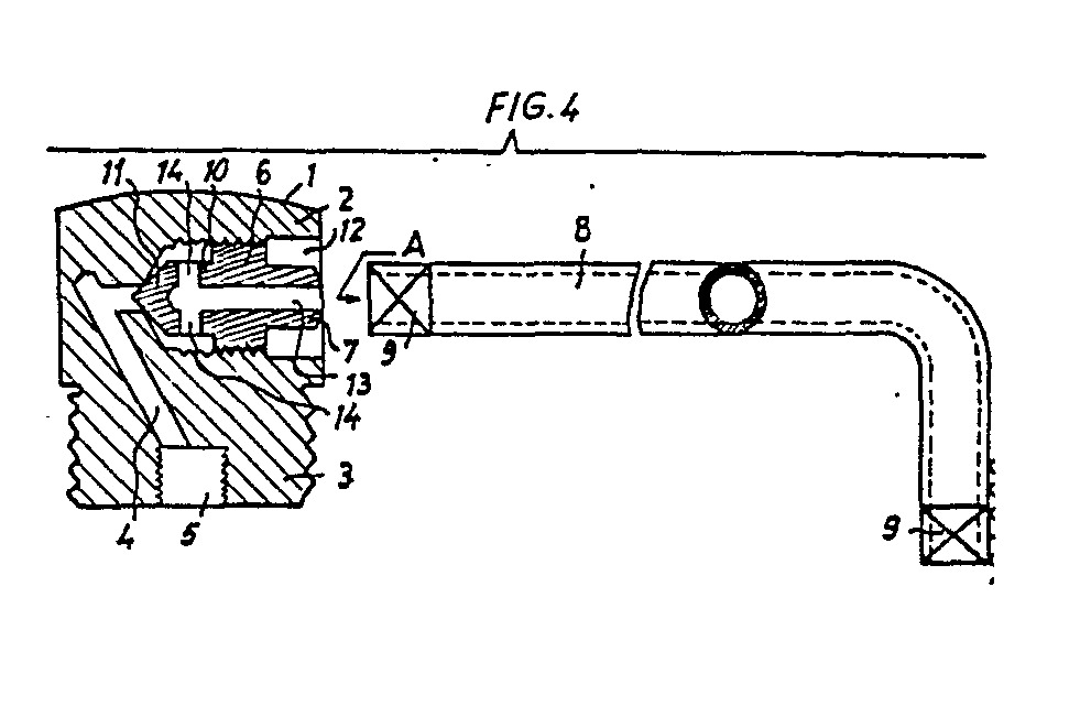
Description
Die Erfindung betrifft einen für Heizkörper bestimmten, in die obere Nabenöffnung eines Heizkörpers eingeschraubten Entlüftungsstopfen mit einem im Innern des Entlüftungsstopfens befindlichen Luftabströmkanal, einer in eine Querbohrung des Entlüftungsstopfens von außen eingeschraubten, zum Verschließen des Luftabströmkanales dienenden, einen verjüngten Fortsatz mit einer Ventilspitze aufweisenden Verschlußschraube und einer Austrittsöffnung am Umfang des Entlüftungsstopfens.The invention relates to a vent plug intended for radiators and screwed into the upper hub opening of a radiator with an air outflow channel located in the interior of the vent plug, a screwed into a transverse bore of the vent plug from the outside, serving to close the air outflow channel, a tapered extension with a valve screw plug an outlet opening on the circumference of the vent plug.
Bei den bisher bekannten Entlüftungsstopfen (vgl. CH-PS 319 487) wird die Luft nach dem Fußboden hin abgeleitet, wobei zwangsweise schmutziges Heizungswasser mitgerissen wird. Eine derartige Ableitung der Luft wirkt sich für den Fall, daß der Heizkörper mit einer Verkleidung versehen ist, insofern nachteilig aus, als in der Regel keine Möglichkeit besteht, das schmutzige Heizungswasser beispielsweise in einer Schale aufzufangen, ohne daß zuvor die Verkleidung entfernt worden ist. Das Entfernen der Verkleidung ist aber häufig umständlich und zeitraubend. Durch das schmutzige Heizungswasser werden aber Fußboden und Wände verschmutzt.In the previously known ventilation plugs (cf. CH-PS 319 487), the air is discharged to the floor, whereby dirty heating water is inevitably entrained. Such a discharge of air has a disadvantage in the event that the radiator is provided with a covering, in that there is generally no possibility of collecting the dirty heating water, for example in a bowl, without the covering having been removed beforehand. Removing the panel is often cumbersome and time consuming. The dirty heating water pollutes the floor and walls.
Der Erfindung liegt daher die Aufgabe zugrunde, einen Entlüftungsstopfen der eingangs beschriebenen Gattung so weiter auszubilden, daß beim Entlüften schmutziges mitgerissenes Heizungswasser außerhalb der Verkleidung der Heizkörper aufgefangen werden kann.The invention is therefore based on the object of developing a vent plug of the type described at the outset in such a way that dirty entrained heating water can be collected outside the paneling of the radiators when venting.
Die Lösung der Aufgabe besteht erfindungsgemäß darin, daß die Verschlußschraube im Innern einen sich vom Kopfende bis in den verjüngten Fortsatz erstreckenden Kanal aufweist, in den in dem verjüngten Fortsatz befindliche Querkanäle münden.The solution to the problem is according to the invention that the screw plug has a channel extending from the head end into the tapered extension into which cross channels located in the tapered extension open.
Die Verschlußschraube ist mit einem Außenvierkant versehen. Der Schaft des zur Betätigung der Verschlußschraube dienenden Steckschlüssels ist durchgehend hohl und längenmäßig so bemessen, daß der Steckschlüssel zum Betätigen der Verschlußschraube mühelos durch einen freien Zwischenraum in der Verkleidung der Heizkörper hindurchgeführt werden kann. Bei Lösen der Verschlußschraube durchströmt in dem Heizkörper befindliche Luft mit mitgerissenem schmutzigen Heizungswasser nach Passieren des Kanals der Verschlußschraube den Schaft des Steckschlüssels, wodurch das schmutzige Heizungswasser außerhalb der Heizkörperverkleidung gezielt aufgefangen werden kann. Es ist dadurch Verschmutzen des Fußbodens und der Wände durch das schmutzige Heizungswasser vermieden.The screw plug is provided with an outer square. The shaft of the socket wrench used to actuate the locking screw is hollow throughout and of such length that the socket wrench for operating the locking screw can be easily passed through a free space in the radiator casing. When the screw plug is loosened, air in the radiator with entrained dirty heating water flows through the socket of the socket wrench after passing through the channel of the screw plug, so that the dirty heating water can be collected outside the radiator cover. This prevents the floor and walls from becoming dirty due to the dirty heating water.
Die Erfindung ist nachstehend anhand der Zeichnung näher erläutert. Es zeigt
- Figur 1 den Entlüftungsstopfen in Seitenansicht,
Figur 2 den Entlüftungsstopfen in gegenüber Figur 1 um 90 0 versetzt in Seitenansicht,Figur 3 den Entlüftungsstopfen in Draufsicht,Figur 4 einen Schnitt nach der Linie IV-IV derFigur 3 mit einem zum Betätigen der Verschlußschraube dienenden Steckschlüssel undFigur 5 den Steckschlüssel in Ansicht in Pfeilrichtung A.
- FIG. 1 the vent plug in a side view,
- FIG. 2 shows the ventilation plug in a side view offset by 9 0 0 compared to FIG. 1,
- FIG. 3 the vent plug in a top view,
- Figure 4 is a section along the line IV-IV of Figure 3 with a socket wrench used to operate the locking screw and
- 5 shows the socket wrench in a view in the direction of arrow A.
Der Entlüftungsstopfen besteht aus dem Stopfenkörper 1, der mit einem Außensechskant 2 und Außengewinde 3 zum Einschrauben in die obere Nabe eines Heizkörpers versehen ist. Der Stopfenkörper 1 weist im Innern einen Luftabströmkanal 4 auf. Dieser ist mit seinem einen Ende schräg nach dem freien Ende des Kernes des Außengewindes 3 hin gerichtet und mündet in ein mit Innengewinde versehenes Bohrloch 5, in das in bekannter Weise ein in der Zeichnung nicht dargestelltes Rohr mit seinem einen Ende einschraubbar ist. Das Rohr befindet sich mit seinem anderen Ende nach Einschrauben des Entlüftungsstopfens in die obere Nabenöffnung eines Heizkörpers in der höchstmöglichen Stellung in dem Heizkörper, um eine einwandfreie Luftabführung sicherzustellen. Mit 6 ist die Verschlußschraube des Entlüftungsstopfens bezeichnet, die mit einem Außenvierkant 7 versehen ist. Die Betätigung der Verschlußschraube 6 erfolgt mittels eines Steckschlüssels 8 mit einem zweischenkeligen Schaft, wobei der eine Schenkel des Schaftes um ein vielfaches länger ist als der andere Schenkel. Der Steckschlüssel 8 besitzt an beiden Enden ein als Innenvierkant ausgebildetes Maul 9. Der Schaft des.Steckschlüssels 8 ist durchgehend hohl. Die Verschlußschraube 6 weist einen verjüngten Fortsatz lo mit einer Ventilspitze 11 auf und ist in einer Querbohrung 12 des Stopfenkörpers 1 eingeschraubt. Im Innern der Verschlußschraube 6 ist ein Kanal 13 vorgesehen, der sich vom Kopfende der Verschlußschraube 6 bis in den verjüngten Fortsatz lo erstreckt. Der Fortsatz lo weist zwei sich gegenüberliegende Querkanäle 14 auf, die in den Kanal 13 münden.The vent plug consists of the plug body 1, which is provided with an
Zum Entlüften der Heizkörper wird für den Fall, daß die Heizkörper mit einer Verkleidung versehen sind, der Steckschlüssel 8 mit dem an dem längeren Schenkel seines Schaftes angeordneten Maul 9 durch einen freien Zwischenraum in der Verkleidung hindurchgeführt und zum Lösen der Verschlußschraube 6 auf deren Außenvierkant 7 aufgesteckt. Nach kurzem Lösen der Verschlußschraube 6 strömt die Luft mit schmutzigem Heizungswasser in die Querbohrung 12, von dort durch die Querkanäle 14 hindurch in den Kanal 13 der Verschlußschraube 6 und weiter durch den Schaft des Steckschlüssels 8 hindurch ins Freie, wobei das schmutzige Heizungswasser außerhalb der Verkleidung aufgefangen werden kann.In order to vent the radiators, in the event that the radiators are provided with a covering, the socket wrench 8 with the
Die Erfindung beschränkt sich in ihrer Anwendung selbstverständlich nicht auf Heizkörper, sondern kann auch bei Warmwasserheizungssystemen schlechthin, bei denen eine Entlüftung erforderlich ist, Anwendung finden.The application of the invention is of course not limited to radiators, but can also be used in hot water heating systems in which ventilation is required.
Claims (1)
Applications Claiming Priority (2)
| Application Number | Priority Date | Filing Date | Title |
|---|---|---|---|
| DE3104355 | 1981-02-07 | ||
| DE19813104355 DE3104355A1 (en) | 1981-02-07 | 1981-02-07 | VENTILATION PLUG, ESPECIALLY FOR RADIATORS |
Publications (2)
| Publication Number | Publication Date |
|---|---|
| EP0061565A2 true EP0061565A2 (en) | 1982-10-06 |
| EP0061565A3 EP0061565A3 (en) | 1983-04-13 |
Family
ID=6124304
Family Applications (1)
| Application Number | Title | Priority Date | Filing Date |
|---|---|---|---|
| EP82100460A Withdrawn EP0061565A3 (en) | 1981-02-07 | 1982-01-23 | Aerating device for radiators |
Country Status (3)
| Country | Link |
|---|---|
| EP (1) | EP0061565A3 (en) |
| DE (1) | DE3104355A1 (en) |
| IT (2) | IT8220737V0 (en) |
Cited By (4)
| Publication number | Priority date | Publication date | Assignee | Title |
|---|---|---|---|---|
| EP0265653A1 (en) * | 1986-10-28 | 1988-05-04 | Horst Eggl | Ventilation collar for radiators |
| DE19506672A1 (en) * | 1995-02-25 | 1996-08-29 | Hummel Anton Verwaltung | Device for emptying and filling radiators |
| CN1071015C (en) * | 1998-10-08 | 2001-09-12 | 关福彦 | Heating radiator screw head |
| CN111140909A (en) * | 2019-12-12 | 2020-05-12 | 郑州宇恒环保技术有限公司 | Multistage compression radiator bottom drainage automatic adjustment tool |
Families Citing this family (3)
| Publication number | Priority date | Publication date | Assignee | Title |
|---|---|---|---|---|
| DE20303986U1 (en) | 2003-03-13 | 2003-05-08 | Anton Hummel Verwaltungs Gmbh, 79183 Waldkirch | Breather valve for radiators with a holding body and an axially adjustable valve body |
| EP3037700B1 (en) * | 2012-06-05 | 2019-09-11 | Delta Systemtechnik GmbH | Method for filling or removal of heating medium |
| GB2572824A (en) * | 2018-04-13 | 2019-10-16 | Beverly Lucas Nigel | Improvements relating to drain valves for domestic radiators |
Family Cites Families (4)
| Publication number | Priority date | Publication date | Assignee | Title |
|---|---|---|---|---|
| GB319493A (en) * | 1928-09-25 | 1929-09-26 | Walter George Case | Improvements in valves or cocks |
| CH319487A (en) * | 1954-04-30 | 1957-02-28 | Trippel Otto | Ventilation device on a central heating body |
| CH386077A (en) * | 1961-10-16 | 1964-12-31 | Strebelwerk Ag | Ventilation device, in particular for radiators |
| DE2111453A1 (en) * | 1971-03-10 | 1972-09-21 | Hummel Metallwarenfab A | Vent valves, preferably for heating systems |
-
1981
- 1981-02-07 DE DE19813104355 patent/DE3104355A1/en not_active Ceased
-
1982
- 1982-01-23 EP EP82100460A patent/EP0061565A3/en not_active Withdrawn
- 1982-02-05 IT IT8220737U patent/IT8220737V0/en unknown
- 1982-02-05 IT IT19478/82A patent/IT1150453B/en active
Cited By (6)
| Publication number | Priority date | Publication date | Assignee | Title |
|---|---|---|---|---|
| EP0265653A1 (en) * | 1986-10-28 | 1988-05-04 | Horst Eggl | Ventilation collar for radiators |
| DE19506672A1 (en) * | 1995-02-25 | 1996-08-29 | Hummel Anton Verwaltung | Device for emptying and filling radiators |
| DE19506672C2 (en) * | 1995-02-25 | 1998-02-19 | Hummel Anton Verwaltung | Device for emptying and filling radiators |
| CN1071015C (en) * | 1998-10-08 | 2001-09-12 | 关福彦 | Heating radiator screw head |
| CN111140909A (en) * | 2019-12-12 | 2020-05-12 | 郑州宇恒环保技术有限公司 | Multistage compression radiator bottom drainage automatic adjustment tool |
| CN111140909B (en) * | 2019-12-12 | 2021-05-28 | 郑州宇恒环保技术有限公司 | Multistage compression radiator bottom drainage automatic adjustment tool |
Also Published As
| Publication number | Publication date |
|---|---|
| IT1150453B (en) | 1986-12-10 |
| EP0061565A3 (en) | 1983-04-13 |
| IT8220737V0 (en) | 1982-02-05 |
| IT8219478A0 (en) | 1982-02-05 |
| DE3104355A1 (en) | 1982-08-19 |
Similar Documents
| Publication | Publication Date | Title |
|---|---|---|
| DE3814683A1 (en) | SCREEN COVER FOR A CLEANING INSERT IN A WATER TREATMENT DEVICE WITH A HOLLOW TUBE | |
| DE3325772C2 (en) | ||
| DE2335915C3 (en) | Device for holding and connecting devices connected in series for controlling and / or conditioning fluids | |
| DE3104355A1 (en) | VENTILATION PLUG, ESPECIALLY FOR RADIATORS | |
| DE1579902C3 (en) | ||
| DE4030142C2 (en) | ||
| CH670690A5 (en) | ||
| DE1105848B (en) | Liquid filter | |
| DE3136647C2 (en) | Device for separating solids from a liquid flow, in particular from a power plant cooling water flow which is contaminated with solids | |
| DE1246606B (en) | Device for introducing air or gas into waste water container or the like. | |
| DE2655935C2 (en) | Spreadable device for attaching tubular winding tubes to spindles | |
| DE20010899U1 (en) | Hydrocyclone | |
| DE3321038C2 (en) | ||
| DE3312654C1 (en) | Floor or ceiling drain | |
| DE1609072A1 (en) | Odor trap | |
| DE4225148A1 (en) | Electric pump or motor terminal box - has separate cable inlet corner unit attachable to different positions on main housing | |
| DE3529116A1 (en) | GARLIC PRESS - WITH SPINDLE OPERATION | |
| EP0629819B1 (en) | Joining piece for automatic fuel oil air exhaust | |
| DE2635923C3 (en) | In-line valve | |
| DE2751948C2 (en) | Combustion device with exhaust fan and several openings for the supply of combustion air and for connection to a corresponding airlock | |
| DE4017121A1 (en) | LIQUID CONTROL ARRANGEMENT | |
| DE3538469C2 (en) | Device for opening the blocked drain head of a centrifugal separator | |
| DE2808239A1 (en) | Sink unit with automatic drying of dishes on draining board - has fan blowing air up through evenly spaced orifices in board surface | |
| DE9212198U1 (en) | Device for filling hot water radiators | |
| CH289617A (en) | Aerator with filter. |
Legal Events
| Date | Code | Title | Description |
|---|---|---|---|
| PUAI | Public reference made under article 153(3) epc to a published international application that has entered the european phase |
Free format text: ORIGINAL CODE: 0009012 |
|
| AK | Designated contracting states |
Designated state(s): FR GB NL SE |
|
| PUAL | Search report despatched |
Free format text: ORIGINAL CODE: 0009013 |
|
| AK | Designated contracting states |
Designated state(s): FR GB NL SE |
|
| STAA | Information on the status of an ep patent application or granted ep patent |
Free format text: STATUS: THE APPLICATION IS DEEMED TO BE WITHDRAWN |
|
| 18D | Application deemed to be withdrawn |
Effective date: 19831214 |
|
| ITF | It: translation for a ep patent filed |