EP0061569B1 - Manchon - Google Patents
Manchon Download PDFInfo
- Publication number
- EP0061569B1 EP0061569B1 EP82100815A EP82100815A EP0061569B1 EP 0061569 B1 EP0061569 B1 EP 0061569B1 EP 82100815 A EP82100815 A EP 82100815A EP 82100815 A EP82100815 A EP 82100815A EP 0061569 B1 EP0061569 B1 EP 0061569B1
- Authority
- EP
- European Patent Office
- Prior art keywords
- sleeve
- section
- ring
- longitudinal
- stiffening sleeve
- Prior art date
- Legal status (The legal status is an assumption and is not a legal conclusion. Google has not performed a legal analysis and makes no representation as to the accuracy of the status listed.)
- Expired
Links
Images
Classifications
-
- F—MECHANICAL ENGINEERING; LIGHTING; HEATING; WEAPONS; BLASTING
- F16—ENGINEERING ELEMENTS AND UNITS; GENERAL MEASURES FOR PRODUCING AND MAINTAINING EFFECTIVE FUNCTIONING OF MACHINES OR INSTALLATIONS; THERMAL INSULATION IN GENERAL
- F16L—PIPES; JOINTS OR FITTINGS FOR PIPES; SUPPORTS FOR PIPES, CABLES OR PROTECTIVE TUBING; MEANS FOR THERMAL INSULATION IN GENERAL
- F16L21/00—Joints with sleeve or socket
- F16L21/002—Sleeves or nipples for pipes of the same diameter; Reduction pieces
- F16L21/005—Sleeves or nipples for pipes of the same diameter; Reduction pieces made of elastic material, e.g. partly or completely surrounded by clamping devices
-
- F—MECHANICAL ENGINEERING; LIGHTING; HEATING; WEAPONS; BLASTING
- F16—ENGINEERING ELEMENTS AND UNITS; GENERAL MEASURES FOR PRODUCING AND MAINTAINING EFFECTIVE FUNCTIONING OF MACHINES OR INSTALLATIONS; THERMAL INSULATION IN GENERAL
- F16L—PIPES; JOINTS OR FITTINGS FOR PIPES; SUPPORTS FOR PIPES, CABLES OR PROTECTIVE TUBING; MEANS FOR THERMAL INSULATION IN GENERAL
- F16L25/00—Construction or details of pipe joints not provided for in, or of interest apart from, groups F16L13/00 - F16L23/00
- F16L25/14—Joints for pipes of different diameters or cross-section
Definitions
- the invention relates to a sleeve of the type mentioned in the preamble of claim 1.
- Sockets of this type are used in particular, but not exclusively, for the repair of pipelines.
- such sleeves can be used wherever two sleeveless pipe ends, so-called spigot ends, which are arranged at least substantially coaxially to one another, are to be tightly connected to one another with a butt joint.
- a sleeve of the type mentioned is known from the document DE-C-1 281 759.
- the known sleeve consists of a rubber sleeve for receiving the two pipe ends to be connected to one another, an axially slotted plastic sleeve surrounding the sleeve on the outside and tensioning straps which are inserted between radial guide ribs so that they are secured against axial displacement.
- the sleeve has a total of two straps, which are each arranged directly on the edge of the sleeve.
- the respective axially outer guide rib for the tensioning band is designed as a radial web projecting radially outward on the outer edge of the sleeve in the manner of a flange.
- the rubber sleeve is axially fixed in the sleeve in that the axially slotted sleeve edge alternately has radially inwardly and radially outwardly bent web sections.
- the radially downwardly curved web sections serve to axially fix the rubber sleeve in that they engage in front of the end faces of the sleeve in the manner of a stop ring.
- the radially outwardly bent web sections serve as a guide or anchoring for the tensioning straps and prevent them from jumping off axially outward from the essentially barrel-shaped sleeve.
- the radially inwardly curved web sections of the known sleeve described above cannot prevent the cuff from jumping over the inner edge of the bent web sections even at the slightest radially inward deformation and thus losing its fixation.
- the sleeve is therefore susceptible to unauthorized and unintentional removal of the sleeve from the sleeve.
- a significantly better axial fixation of the sleeve and the cuff against one another is achieved with the sleeve known from the documents DE-U-7 037 and DE-C-2 109 566.
- the outer edge areas of the rubber sleeve encompass the two opposite outer edges of the sleeve and are forced onto the outside of the sleeve by the tensioning straps.
- a disadvantage of this arrangement is that the tensioning straps "float", ie. H. do not transfer the clamping force required to ensure the tightness of the sleeve directly to the rigid sleeve and from there to the sealing area of the rubber sleeve, but instead act in a damped and buffered manner on the outer jacket of the sleeve.
- the invention has for its object to provide a sleeve of the type mentioned, in which the sleeve and the sleeve are connected to an axially sufficiently stabilized unit in particular, without the need for an excessive use of elastomer, and in which the straps rest directly on the outer surface of the sleeve.
- the invention thus creates a sleeve consisting of a sleeve, sleeve and tensioning straps, in which the radially outwardly projecting radial web on the sleeve edge does not serve to guide the tensioning straps, but rather serves to axially fixate and improve the overall rigidity of the sleeve by virtue of the fact that this radial web extends from the outer edges the cuff is encompassed, in particular in such a way that the radial web is reinforced by a ring-like Section of the sleeve is gripped axially.
- this ring section of the cuff preferably has an at least substantially circular or square cross section, more precisely a cord cross section.
- the inner ring diameter of this ring section of the cuff is preferably further dimensioned such that it encloses the sleeve under radial prestress.
- the sleeve of the invention also forms a fixed structural unit without tensioning straps, in which in particular the sleeve and the sleeve are fixed axially firmly against one another.
- the sleeve can be easily transported, handled and used to produce the pipe connections without the risk of changing the axial nominal position of the sleeve and the sleeve.
- the bond between the sleeve and sleeve is also particularly inexpensive to manufacture, d. H. pre-assembled. To produce this composite, the tensioning straps do not need to be put on or even pulled into closed guides, nor does the sleeve edge need to be deformed during the pre-assembly of the sleeve.
- the cuff is preferably made of conventional rubber qualities, but can also be easily made from appropriate plastics, as long as the application specifications allow.
- the tensioning straps consist in particular of steel, especially corrosion-resistant steel, or of tensile plastics, or corresponding composite materials.
- the tensioning means used for tensioning the tensioning straps are of a common type and are known in large numbers, so that their detailed explanation within the scope of the invention is omitted.
- the sleeve preferably consists of a material which, on the one hand, gives the sleeve sufficient dimensional stability, but, on the other hand, retains the deformability required to bridge tolerances and roundness of the pipe ends to be connected. From these points of view, the sleeve preferably consists of corrosion-resistant steel sheet or of plastic, in particular reinforced plastic.
- the sleeve has annular, radially outwardly projecting guide ribs, which are integrally formed on the sleeve or formed from it.
- the tensioning straps are inserted between these guide ribs.
- the axially outermost guide rib is located so far axially inward from the outer edge of the sleeve that the distance between the inner edge of the radial web on the sleeve edge and the axially outer edge of this guide rib is at least approximately the same size as the axial width of the annular portion of the sleeve.
- the sleeve preferably has axial incisions which extend axially inward from the outer edge of the sleeve, namely to below the tensioning straps, preferably to an axial depth which extends axially inward beyond the tensioning straps.
- These incisions serve the purpose of being able to absorb large and very large deviations of the actual outside diameter of the pipe ends to be connected from the nominal diameters and also of greater roundness of the pipe ends without impairing the tightness of the pipe connection.
- a further adaptability to deviations in the dimensions of the pipe ends to be connected from given nominal dimensions with simultaneous further stabilization of the sleeve and a noticeable pre-assembly and assembly ease is achieved if the sleeve is not cylindrically closed, but is designed as an open band, according to one embodiment of the invention
- Ends overlap in the area of a tongue formed on one of the two ends, the axial width of which is dimensioned such that the tongue runs between two tensioning straps arranged in the edge areas, without getting under a tensioning strap at any point.
- the formed tongue, with which the open sleeve band overlaps, is therefore narrower in the axial direction than the inner edge spacing between the two annular guide ribs for the tensioning bands lying opposite one another in the outer edge regions of the sleeve.
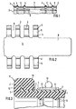
- a sleeve 1 of the sleeve of the invention is an at least substantially cylindrical sleeve made of corrosion-resistant steel sheet.
- the outer edges of the sleeve are flanged to form a radial web 2 for anchoring a sleeve radially outward.
- the radial web 2 is adjoined by a smooth cylindrical section 3 of the jacket of the sleeve 1, which serves to receive a ring-like reinforcement of the sleeve pulled around the radial web 2.
- the cylindrical sleeve section 3 is delimited by one of two annular guide ribs 4, which are designed as radially projecting beads. Between the two annular guide ribs 4, 4, a smooth cylindrical sleeve section 5 is again formed, the axial width of which at least substantially corresponds to the width of a tensioning band to be inserted between the two guide ribs 4.
- the sleeve 1 also has an equal angular distance from one another over its entire circumference, a series of axial slots 6 which extend axially inward from the outer edge 7 of the sleeve 1 to behind the second annular guide rib 4. These axial slots 6 enable the tensioning straps which are placed around the sleeve 1 in the cylindrical sections 5 to bring about a reduction in the diameter of the sleeve 1 when tightening. This serves to generate a radially inward contact pressure on the internal rubber sleeve for sealing purposes.
- FIG. 2 In contrast to the exemplary embodiment of a sleeve of the sleeve shown in FIG. 1, an end of a sleeve 1 designed as an open band is shown in plan view in FIG. 2.
- the sleeve 1 again consists of corrosion-resistant steel sheet.
- the sleeve 1 are designed to be substantially wider than in the embodiment shown in FIG. 1 and have the same width as the web-like or finger-like sleeve sections that remain between two successive slots, which essentially consist of the radial web 2, the first cylindrical section 3, the two Guide ribs 4 and the cylindrical portion 5 formed between these two guide ribs.
- a tongue 8 is formed which, based on the band forming the sleeve, extends axially and, based on the cylindrical sleeve, in the circumferential direction so far that it Even with the largest permissible circumference of the sleeve for stabilization, the opposite end of the band overlaps sufficiently, preferably in particular radially inside, seen from the outside so that it overlaps the opposite end.
- the width of the tongue 8 is dimensioned such that it is narrower than the distance between the two axially innermost guide ribs 4, 4 'from one another. This ensures that the tongue is not impaired in its displaceability and mobility in the circumferential direction by the tightened tensioning straps which lie in the cylindrical sections 5. Such mobility promotes assembly security and facilitates the assembly process.
- FIG. 3 An embodiment of the complete sleeve of the invention is shown in axial section and in partial representation in FIG. 3.
- the sleeve 1 is made of plastic and has on its outer edge a flange-shaped radial web 2.
- the sleeve 9 surrounds with its outer edge 10 the outer wheel 7 and the radial web 2 of the sleeve 1, in such a way that an annular reinforcement 11 formed on the outer edge 10 of the sleeve 9 engages behind the annular web 2 from the inside axially.
- the ring web 2 is clamped axially between the outer edge 10 and the ring section 11 of the sleeve 9.
- the ring section 11 of the sleeve 9 also has a radial prestress.
- the ring portion 11 of the sleeve 9 has a substantially square cross-section with strongly rounded edges.
- the ring section 11 is dimensioned such that a considerable force is required to radially expand the ring section 11.
- a tensioning band 12 is inserted, secured against axial displacement, which can be tensioned by means of schematically indicated tensioning means 13 in the sense of a radius reduction.
- the radially inward force generated by this reduction in radius is transmitted directly to the cylindrical section 5 of the sleeve 1 and from this sleeve 1 to the sleeve 9 and to sealing elements 14 formed thereon, which seal the inner jacket of the sleeve against the outer jacket of an inserted pipe end.
- the sealing elements 14 are shown in the exemplary embodiment shown here as simple bead rings. In practice, of course, they can also have any other shape, in particular also be lip-shaped.
Landscapes
- Engineering & Computer Science (AREA)
- General Engineering & Computer Science (AREA)
- Mechanical Engineering (AREA)
- Clamps And Clips (AREA)
- Protection Of Pipes Against Damage, Friction, And Corrosion (AREA)
- Mutual Connection Of Rods And Tubes (AREA)
- Semiconductor Lasers (AREA)
- Crystals, And After-Treatments Of Crystals (AREA)
- Glass Compositions (AREA)
- Joints With Sleeves (AREA)
Claims (4)
Priority Applications (1)
| Application Number | Priority Date | Filing Date | Title |
|---|---|---|---|
| AT82100815T ATE8172T1 (de) | 1981-03-27 | 1982-02-04 | Muffe. |
Applications Claiming Priority (2)
| Application Number | Priority Date | Filing Date | Title |
|---|---|---|---|
| DE3112258 | 1981-03-27 | ||
| DE19813112258 DE3112258A1 (de) | 1981-03-27 | 1981-03-27 | Muffe |
Publications (2)
| Publication Number | Publication Date |
|---|---|
| EP0061569A1 EP0061569A1 (fr) | 1982-10-06 |
| EP0061569B1 true EP0061569B1 (fr) | 1984-06-27 |
Family
ID=6128529
Family Applications (1)
| Application Number | Title | Priority Date | Filing Date |
|---|---|---|---|
| EP82100815A Expired EP0061569B1 (fr) | 1981-03-27 | 1982-02-04 | Manchon |
Country Status (4)
| Country | Link |
|---|---|
| US (1) | US4491350A (fr) |
| EP (1) | EP0061569B1 (fr) |
| AT (1) | ATE8172T1 (fr) |
| DE (2) | DE3112258A1 (fr) |
Families Citing this family (14)
| Publication number | Priority date | Publication date | Assignee | Title |
|---|---|---|---|---|
| JPH0516838Y2 (fr) * | 1987-03-04 | 1993-05-06 | ||
| US4927189A (en) * | 1989-04-10 | 1990-05-22 | Burkit John W | Internal expansion coupling device |
| GB2253452B (en) * | 1991-03-05 | 1994-09-14 | Victaulic Plc | Pipe couplings |
| DE4207849C2 (de) * | 1992-03-12 | 1997-12-04 | Henrik Muecher | Rohrkupplung zum dichten Verbinden von glatten Enden zweier Rohre |
| FR2784166B1 (fr) * | 1998-10-02 | 2000-11-17 | Renault | Agencement pour le raccordement demontable et etanche entre un embout et un conduit d'un circuit d'air de vehicule automobile |
| DE102005032341B3 (de) * | 2005-07-08 | 2007-02-15 | Mündener Gummiwerk Gmbh | Muffe eines Ladeluftschlauches zur Anbringung des Ladeluftschlauches an einen Stutzen |
| US20090051166A1 (en) * | 2007-05-17 | 2009-02-26 | Murray Corporation | Clamp-fitting stop |
| JP5075488B2 (ja) * | 2007-06-06 | 2012-11-21 | 矢崎総業株式会社 | コネクタ |
| DE102007061288B4 (de) | 2007-12-19 | 2010-03-11 | Felber, Winfried | Vorrichtung zum Verbinden von zwei Leitungen |
| DE202011107927U1 (de) * | 2011-11-16 | 2013-02-20 | M.D.S. Meyer Gmbh | Verbindungsvorrichtung zum Verbinden von zwei Rohren |
| US9683691B2 (en) * | 2013-05-20 | 2017-06-20 | Ford Global Technologies, Llc | Hose and system for hose clamp registration |
| JP6008249B2 (ja) * | 2013-07-04 | 2016-10-19 | 住友電装株式会社 | グロメット |
| GB201701347D0 (en) * | 2017-01-27 | 2017-03-15 | Flex-Seal Couplings Ltd | Improvements in or relating to pipe couplings |
| US20210285579A1 (en) * | 2020-03-13 | 2021-09-16 | Steere Enterprises, Inc. | Duct connector |
Citations (3)
| Publication number | Priority date | Publication date | Assignee | Title |
|---|---|---|---|---|
| DE7037139U (fr) * | 1900-01-01 | Muecher H Muecher Ringe | ||
| DE1211045B (de) * | 1958-02-24 | 1966-02-17 | Scottish Agricultural Ind Ltd | Rohrkupplung |
| DE2109566C (fr) * | 1971-03-01 | 1973-07-12 |
Family Cites Families (10)
| Publication number | Priority date | Publication date | Assignee | Title |
|---|---|---|---|---|
| DE925743C (de) * | 1953-12-23 | 1955-03-28 | Ingbuero Hollender & Co | Isolierende und waermefeste Rohrverbindung |
| US3334928A (en) * | 1965-03-10 | 1967-08-08 | John D Schmunk | Pipe coupling |
| DE1281759B (de) * | 1966-08-16 | 1969-04-30 | Jurid Werke Gmbh | Spannhuelse zum Klemmen von Abdichtungsmanschetten fuer die Verbindung von muffenlosen, glatten Rohren |
| US3430989A (en) * | 1967-12-20 | 1969-03-04 | Pacific Clay Products | Pipe coupling |
| US3682503A (en) * | 1970-09-11 | 1972-08-08 | Peerless Ind Inc | Pipe joint |
| DE2109566B2 (de) * | 1971-03-01 | 1972-12-21 | Hermann Mücher Mücher-Ringe, 5830 Schwelm | Kupplungsmanschette und verfahren zu ihrer herstellung |
| US3796446A (en) * | 1971-12-10 | 1974-03-12 | Gen Connector Corp | Connector |
| ZA732442B (en) * | 1972-04-20 | 1975-01-29 | Wavin Bv | Pipe connection for plastic pipes comprising a transversly or helically corrugated pipe-connecting parat |
| US3840053A (en) * | 1973-02-05 | 1974-10-08 | Dresser Ind | Inside repair clamp for low pressure piping |
| US4380348A (en) * | 1981-02-18 | 1983-04-19 | Clamp-All Corp. | Pipe clamping assembly |
-
1981
- 1981-03-27 DE DE19813112258 patent/DE3112258A1/de not_active Withdrawn
-
1982
- 1982-02-04 EP EP82100815A patent/EP0061569B1/fr not_active Expired
- 1982-02-04 AT AT82100815T patent/ATE8172T1/de not_active IP Right Cessation
- 1982-02-04 DE DE8282100815T patent/DE3260281D1/de not_active Expired
- 1982-03-10 US US06/356,690 patent/US4491350A/en not_active Expired - Fee Related
Patent Citations (3)
| Publication number | Priority date | Publication date | Assignee | Title |
|---|---|---|---|---|
| DE7037139U (fr) * | 1900-01-01 | Muecher H Muecher Ringe | ||
| DE1211045B (de) * | 1958-02-24 | 1966-02-17 | Scottish Agricultural Ind Ltd | Rohrkupplung |
| DE2109566C (fr) * | 1971-03-01 | 1973-07-12 |
Also Published As
| Publication number | Publication date |
|---|---|
| ATE8172T1 (de) | 1984-07-15 |
| DE3112258A1 (de) | 1982-10-07 |
| DE3260281D1 (en) | 1984-08-02 |
| US4491350A (en) | 1985-01-01 |
| EP0061569A1 (fr) | 1982-10-06 |
Similar Documents
| Publication | Publication Date | Title |
|---|---|---|
| EP0728979B1 (fr) | Raccord étanche entre un tuyau en matière plastique et une pièce de raccordement fabriquée en métal | |
| DE69900615T2 (de) | Vorrichtung zum Verbinden einer Rohrkupplung | |
| DE3424675C2 (de) | Schlauchkupplung | |
| DE3815173C2 (fr) | ||
| EP2463565B1 (fr) | Agencement de jonction de conduites | |
| DE2058203C2 (de) | Rohrverbinder | |
| CH667904A5 (de) | Rohrkupplung. | |
| CH664612A5 (de) | Steckkupplung zum verbinden der enden zweier rohre. | |
| CH647586A5 (de) | Schlauchbandklemme. | |
| EP0061569A1 (fr) | Manchon | |
| DE102007061288A1 (de) | Vorrichtung zum Verbinden von zwei Leitungen | |
| DE202016104723U1 (de) | Dichtungsmanschette zum Einsetzen in ein Rohrleitungssystem | |
| DE69931773T2 (de) | Rohrverbindung | |
| DE2517808B2 (de) | Rohrkupplung | |
| DE3247452C1 (de) | Rohrverbindung | |
| DE19542463B4 (de) | Rohrkupplung | |
| DE60212270T2 (de) | Verbindungsmuffe mit in axialer Richtung zusammengedrückter Dichtring | |
| DE1650200C3 (de) | Dichtungsanordnung zur abdichtenden Überbrückung der mit oder ohne Endbunden ausgestatteten Enden von Rohren | |
| DE2221674A1 (de) | Schlauchkupplung | |
| DE19615861A1 (de) | Faltenbalg mit beschichteten Bundbereichen | |
| DE2758592A1 (de) | Verbindungsausbildung zur befestigung eines rohres in der oeffnung einer wandung | |
| DE2440886C3 (de) | Rohrverbindung für Druckrohrleitungen | |
| DE69212784T2 (de) | Abgasleitungssegment mit Doppelsteckmuffe | |
| DE2638622C3 (de) | Elastisches Rohrverbindungsstück | |
| DE4241622A1 (de) | Rohrkupplung |
Legal Events
| Date | Code | Title | Description |
|---|---|---|---|
| PUAI | Public reference made under article 153(3) epc to a published international application that has entered the european phase |
Free format text: ORIGINAL CODE: 0009012 |
|
| AK | Designated contracting states |
Designated state(s): AT BE CH DE FR GB IT NL SE |
|
| 17P | Request for examination filed |
Effective date: 19821007 |
|
| ITF | It: translation for a ep patent filed | ||
| GRAA | (expected) grant |
Free format text: ORIGINAL CODE: 0009210 |
|
| AK | Designated contracting states |
Designated state(s): AT BE CH DE FR GB IT LI NL SE |
|
| REF | Corresponds to: |
Ref document number: 8172 Country of ref document: AT Date of ref document: 19840715 Kind code of ref document: T |
|
| REF | Corresponds to: |
Ref document number: 3260281 Country of ref document: DE Date of ref document: 19840802 |
|
| ET | Fr: translation filed | ||
| PLBE | No opposition filed within time limit |
Free format text: ORIGINAL CODE: 0009261 |
|
| STAA | Information on the status of an ep patent application or granted ep patent |
Free format text: STATUS: NO OPPOSITION FILED WITHIN TIME LIMIT |
|
| 26N | No opposition filed | ||
| ITTA | It: last paid annual fee | ||
| PGFP | Annual fee paid to national office [announced via postgrant information from national office to epo] |
Ref country code: AT Payment date: 19930125 Year of fee payment: 12 |
|
| PGFP | Annual fee paid to national office [announced via postgrant information from national office to epo] |
Ref country code: SE Payment date: 19930218 Year of fee payment: 12 |
|
| PG25 | Lapsed in a contracting state [announced via postgrant information from national office to epo] |
Ref country code: AT Effective date: 19940204 |
|
| PG25 | Lapsed in a contracting state [announced via postgrant information from national office to epo] |
Ref country code: SE Effective date: 19940205 |
|
| EUG | Se: european patent has lapsed |
Ref document number: 82100815.8 Effective date: 19940910 |
|
| PGFP | Annual fee paid to national office [announced via postgrant information from national office to epo] |
Ref country code: GB Payment date: 19960111 Year of fee payment: 15 |
|
| PGFP | Annual fee paid to national office [announced via postgrant information from national office to epo] |
Ref country code: FR Payment date: 19960129 Year of fee payment: 15 |
|
| PGFP | Annual fee paid to national office [announced via postgrant information from national office to epo] |
Ref country code: CH Payment date: 19960201 Year of fee payment: 15 |
|
| PG25 | Lapsed in a contracting state [announced via postgrant information from national office to epo] |
Ref country code: GB Effective date: 19970204 |
|
| PGFP | Annual fee paid to national office [announced via postgrant information from national office to epo] |
Ref country code: BE Payment date: 19970214 Year of fee payment: 16 |
|
| PGFP | Annual fee paid to national office [announced via postgrant information from national office to epo] |
Ref country code: NL Payment date: 19970220 Year of fee payment: 16 |
|
| PG25 | Lapsed in a contracting state [announced via postgrant information from national office to epo] |
Ref country code: LI Effective date: 19970228 Ref country code: CH Effective date: 19970228 |
|
| PGFP | Annual fee paid to national office [announced via postgrant information from national office to epo] |
Ref country code: DE Payment date: 19970401 Year of fee payment: 16 |
|
| GBPC | Gb: european patent ceased through non-payment of renewal fee |
Effective date: 19970204 |
|
| REG | Reference to a national code |
Ref country code: CH Ref legal event code: PL |
|
| PG25 | Lapsed in a contracting state [announced via postgrant information from national office to epo] |
Ref country code: FR Effective date: 19971030 |
|
| REG | Reference to a national code |
Ref country code: FR Ref legal event code: ST |
|
| PG25 | Lapsed in a contracting state [announced via postgrant information from national office to epo] |
Ref country code: BE Free format text: LAPSE BECAUSE OF NON-PAYMENT OF DUE FEES Effective date: 19980228 |
|
| BERE | Be: lapsed |
Owner name: WOCO FRANZ-JOSEF WOLF & CO. Effective date: 19980228 |
|
| PG25 | Lapsed in a contracting state [announced via postgrant information from national office to epo] |
Ref country code: NL Free format text: LAPSE BECAUSE OF NON-PAYMENT OF DUE FEES Effective date: 19980901 |
|
| NLV4 | Nl: lapsed or anulled due to non-payment of the annual fee |
Effective date: 19980901 |
|
| PG25 | Lapsed in a contracting state [announced via postgrant information from national office to epo] |
Ref country code: DE Free format text: LAPSE BECAUSE OF NON-PAYMENT OF DUE FEES Effective date: 19981103 |