EP0061576B1 - Dispositif de transmission d'informations à micro-ondes avec réception combinée de diversité multimode - Google Patents
Dispositif de transmission d'informations à micro-ondes avec réception combinée de diversité multimode Download PDFInfo
- Publication number
- EP0061576B1 EP0061576B1 EP82101197A EP82101197A EP0061576B1 EP 0061576 B1 EP0061576 B1 EP 0061576B1 EP 82101197 A EP82101197 A EP 82101197A EP 82101197 A EP82101197 A EP 82101197A EP 0061576 B1 EP0061576 B1 EP 0061576B1
- Authority
- EP
- European Patent Office
- Prior art keywords
- wave
- types
- exciter
- waveguide
- lobe
- Prior art date
- Legal status (The legal status is an assumption and is not a legal conclusion. Google has not performed a legal analysis and makes no representation as to the accuracy of the status listed.)
- Expired
Links
Images


Classifications
-
- H—ELECTRICITY
- H04—ELECTRIC COMMUNICATION TECHNIQUE
- H04B—TRANSMISSION
- H04B7/00—Radio transmission systems, i.e. using radiation field
- H04B7/02—Diversity systems; Multi-antenna system, i.e. transmission or reception using multiple antennas
- H04B7/10—Polarisation diversity; Directional diversity
-
- H—ELECTRICITY
- H01—ELECTRIC ELEMENTS
- H01Q—ANTENNAS, i.e. RADIO AERIALS
- H01Q25/00—Antennas or antenna systems providing at least two radiating patterns
- H01Q25/04—Multimode antennas
Definitions
- German patent 2626925 describes a method which mitigates the effects of the statistical fluctuations in the microwave transmission links by coupling more than one wave type in the waveguide-fed receiving antenna to obtain angle diversity signals. This method is based on the fact that, in a very large percentage of the transmission duration, at least one wave type delivers an evaluable reception signal. With this known method it is possible, for example with a single receiving antenna, to set up a dual-angle diversity system which feeds the two received signals obtained from the different wave types to separate receivers and derives a best signal therefrom.
- a direction finding system for locating moving reflecting objects is known, in which several types of waveguide waves are used in the antenna feed system.
- the main wave type to be evaluated and the higher wave types provide direction information of the reflecting moving object, so that the antenna can be tracked accordingly and a cannon control or a missile guidance system can be controlled accordingly.
- the arrangement disclosed here achieves a completely different task, namely the location of a moving object.
- the invention has for its object to provide a message transmission device for microwaves with multi-path propagation, which works on the angle diversity principle, works with only one antenna and one exciter per terminal and with which an increase in the independent transmission paths is achieved, the antenna gain of all Radiation lobes involved are increased in order to achieve a more effective combination of the received signals into a best signal than was previously possible.
- the transmit and receive operations should be simple, i. H. without an additional circulator, this antenna can be used simultaneously.
- the present invention relates to further development, i. h, improvement of the method described in German Patent 2626925 to ensure uninterrupted message traffic with a microwave transmission system with multipath propagation.
- a microwave transmission system usually consists of a radio field (approx. 40 ... 150 km long) and at the ends of at least one antenna with transmitting and receiving devices. If there is a multipath propagation in radio fields that, for example, do not have an optical view (e.g. microwave transmission with the help of tropospheric scattered radiation), the reception signal very often dips in due to interference of the partial waves.
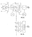
- a Cassegrain system is preferred as the antenna system. It consists of a main reflector R, subreflector SR and exciter horn E.
- the effective focal length of this type of reflector is generally larger than that of a focus-fed antenna type. The consequence of this is that the excitation aperture c must be chosen to be comparatively larger, which favors the existence of higher waveguide types.
- the downstream mode switch M separates the energy components of different wave types of the excitation horn and provides, for example, three receive outputs E i , E2, E3 and one transmit input S. The transmit input can be assigned to the wave type of a receive output.
- the three receive outputs E 1 , E 2 , E 3 can - as shown in Fig. 1 a - feed an RF combiner, which is controlled by the receiver E via a control unit St, so that a high-frequency best signal is provided at its output, which is offered to the recipient E.
- the RF combiner can in a known manner, such as. B. in the journal NTG-Fachbericht, Vol. 70, p. 199, in the article "Electronic Space Diversity System for Directional Radio Systems” by Ulrich H. Sysel.
- an IF or a so-called baseband combiner can also be used, which is operated by three separate receivers E ', E ", E"'.
- Such an arrangement is described in a company brochure from Motorola "MVEC-70 Predetection Combiner".
- the H io shaft is suitable as the main lobe and the H 20 shaft as the angle diversity lobe (see German Patent 2626925).
- the H 10 wave can simultaneously serve as a carrier of the transmission signal.
- a field configuration results in the excitation aperture according to FIG. 2a and the shape of the antenna lobes according to FIG. 2b is derived therefrom.
- 3b schematically shows the associated lobe configuration as a level range. This lobe configuration is spread both in the azimuth and in the elevation plane and has four equal field strength maxima. All four individual clubs have the same maximum profit. 21 -wave and E HE 21 -Welle - in the case of a groove pathogen takes the place of the H 21st
- Fig. 4 shows in perspective the structure of a feed system for multi-mode diversity combination reception, consisting of exciter, subreflector and mode coupler.
- the mode coupler M has a total of four waveguide gates, three of which can be used for mode diversity combination reception (E i , E2, E3).
- the fourth gate (S) can be used as a transmission input.
- the output E 1 is coupled to the H 10 wave, E 2 to the H 11 + E 11 wave and E 3 to the H 20 wave.
- the input S transmits the orthogonal polarization (H 01 wave).
- the use of Gate S as a transmission input is an elegant way of separating transmission and reception. By decoupling the shaft types from one another, all reception gates are decoupled from the transmission gate.
- the vertical expansion lobe would look into the ground with its lower half of the lobe and lose a large part of its reception gain if the installation position was not rotated.
- the spreading angle is reduced by a factor in relation to the vertical plane so that with the same angle of attack of the antenna, a higher reception gain in the previously vertically spread diversity lobe can be expected.
- this measure also rotates the previously horizontally oriented spreading lobe by 45 °, so that the same conditions (due to the antenna orientation) can now be expected in both spreading lobes.
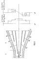
- the exciter horn is followed by a rectangular waveguide H, in which all the wave types to be evaluated must be viable.
- the energy components of the H 01 shaft and the H 20 shaft are coupled through a pair of axially oriented and pairwise opposite waveguide windows F and separated in a double-T junction T via symmetrical waveguides L 1 , L 2 .
- the separating plate B arranged symmetrically in the waveguide sections H i , H 2 prevents the H 01 wave from spreading into the rear section of the mode coupler H 2 .
- the position of the sheet B along the axis of the mode coupler is of decisive importance for the adaptation that can be achieved when coupling the H 01 shaft.
- the partition B has another task; it converts the H 11 + E 11 wave arriving from the exciter into two antiphase waveguide waves, the energy of which is then selectively coupled into the laterally attached waveguide E2 using a coupling bracket K.
- the H 10 shaft runs relatively undisturbed along the axis into the rear exit E i .
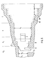
- a section (FIG. 5) in the H plane through the waveguide sections H, H 1 , H 2 and through the exciter horn E illustrates the internal structure of the feed system.
- the front waveguide H has the width a 1 and the height b i .
- This width enables the existence of the H 20 wave in the waveguide H, the height b, but not the existence of the H o2 wave, but the existence of the H 01 wave.
- the width is either reduced gradually (ST) or steadily to the dimension a 2 , which, together with an additional reduction in the waveguide height from b 1 to b 2, only permits the H 10 wave. If all of the shaft types described are used, care must be taken that the waveguide height b i is chosen so large that, in addition to the H 01 shaft to be transmitted, the H 11 + E 11 shaft remains viable up to the separating plate B.
- the diaphragm B can be pulled into the front waveguide H.
- a transmission signal to be transmitted must be transmitted in addition to the reception signal via gate 1 (H 01 wave), which is possible in a known manner by means of a circulator connection.
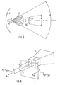
- the design of the pathogen is of particular importance in the case of a multi-mode diversity antenna. This is largely responsible for achieving high antenna gains.
- the following illumination conditions result for a main wave type H lo and a higher wave type H 20 in the antenna according to FIG. 6. While a large part of the primary lobe HK of the main wave type H lo formed by the exciter falls on the subreflector SR in the illumination angle range a, that remains hatched area of the spreading lobe SK (H 20 shaft) outside the footprint and is therefore lost for the antenna gain. In this case, the normal expected antenna gain for the main lobe occurs, for the spreading lobe a significant decrease in profit has to be observed. In the classic case, a compromise between the two antenna lobes is possible, in which the beam angle is increased by changing the antenna geometry and more energy is used by the spreading lobe.
- additional measures according to the invention are intended to enable a further increase in antenna gain without having to compromise. This is achieved according to the invention in such a way that the primary lobes H 10 , H 01 belonging to the main shaft types are widened (see dashed line) without significantly narrowing the expansion lobe. After the widening has been carried out, the antenna geometry must be readjusted, ie the horn aperture or the subreflector is adapted to the new conditions.
- the introduction of a grooved exciter is very advantageous (symmetrical radiation, lobe shape in the H and E planes). Furthermore, by introducing step-shaped cross-sectional expansions or kinks as shown in FIG. 5, excitation of further hybrid wave types is achieved which achieve the desired beam-lobe broadening in both polarizations of the exciter (here HE 11 waves).
- the excited wave would be here in particular re to name the H 13 wave for the H plane or the HE 31 wave for the E plane, which, when superimposed with the HE 11 wave and with a suitable phase position, causes a field concentration in the center of the aperture of the exciter and thus the desired lobe broadening Consequence.
- the lengths 1 s of the steps or buckling sections and their distance 1 a to the excitation aperture are chosen such that the phase position shown in FIG. 7 is created.
- the cross-sectional structure of the horn is chosen to be square in all horn sections using both polarizations of the main shaft type (HE 11 ).
- the arrangement of several stages SH (Fig. 5) makes the effect described broadband.
- FIG. 8 Let us first consider the level of the electric fields (FIG. 8). Basically, kinks, jumps, etc. are also possible here in order to obtain a broadening of the main shaft-type lobe, but the introduction of the apertures B 1 , B 2 , B 3 , B 4 results in a very simple possibility in the opposite way of the radiation lobes of the to align the higher wave type with its beam angle to the lobe of the main wave type. Rotational symmetry is achieved by choosing the aspect ratio of the rectangular aperture of the exciter horn.
- Fig. 8 the end of the separating plate B (mode coupler) together with the inner structure of the rectangular or square exciter horn E is drawn in section.
- the exciter horn is symmetrically divided into chambers by the diaphragms B 1 , B 2 , B 3 , B 4 .
- This chamber horn is known per se, but it is modified for use with several wave types in such a way that a widening of the radiation lobe of the main wave type H lo and a narrowing of the radiation lobe of the higher wave type H 11 + E 11 results in the E plane.
- the inclination of the diaphragms to the horn walls W results in a changed field distribution in the aperture plane A compared to the undisturbed (no diaphragms in the horn) conditions, which is schematically plotted along the straight line A.
- the originally expected, undisturbed distribution is shown in dashed lines.
- there is now a stronger field concentration in the middle of the exciter horn which leads to a broadening of the radiation lobe of the exciter horn. This measure only makes sense if at the same time the width of the radiation lobe assigned to (or derived from) the higher wave type remains the same or can possibly be made even narrower.
- Fig. 9 shows this arrangement, which consists of four partial waveguides opening into the exciter, all of which are connected together with magic T's (T 1 , T 2 , T 3 , T 4 ), so that the energies of the different wave types are available at their outputs .
Landscapes
- Engineering & Computer Science (AREA)
- Computer Networks & Wireless Communication (AREA)
- Signal Processing (AREA)
- Variable-Direction Aerials And Aerial Arrays (AREA)
- Waveguide Aerials (AREA)
- Aerials With Secondary Devices (AREA)
Claims (4)
Applications Claiming Priority (2)
| Application Number | Priority Date | Filing Date | Title |
|---|---|---|---|
| DE19813111731 DE3111731A1 (de) | 1981-03-25 | 1981-03-25 | Mikrowellenuebertragungseinrichtung mit mehrmodendiversity-kombinationsempfang |
| DE3111731 | 1981-03-25 |
Publications (2)
| Publication Number | Publication Date |
|---|---|
| EP0061576A1 EP0061576A1 (fr) | 1982-10-06 |
| EP0061576B1 true EP0061576B1 (fr) | 1985-05-02 |
Family
ID=6128248
Family Applications (1)
| Application Number | Title | Priority Date | Filing Date |
|---|---|---|---|
| EP82101197A Expired EP0061576B1 (fr) | 1981-03-25 | 1982-02-18 | Dispositif de transmission d'informations à micro-ondes avec réception combinée de diversité multimode |
Country Status (4)
| Country | Link |
|---|---|
| US (1) | US4473828A (fr) |
| EP (1) | EP0061576B1 (fr) |
| CA (1) | CA1180801A (fr) |
| DE (2) | DE3111731A1 (fr) |
Cited By (2)
| Publication number | Priority date | Publication date | Assignee | Title |
|---|---|---|---|---|
| DE3604432A1 (de) * | 1986-02-13 | 1987-08-20 | Licentia Gmbh | Modenkoppler fuer monopulsanwendungen |
| DE3840450A1 (de) * | 1988-12-01 | 1990-06-07 | Telefunken Systemtechnik | Modenkoppler fuer monopulsanwendungen |
Families Citing this family (28)
| Publication number | Priority date | Publication date | Assignee | Title |
|---|---|---|---|---|
| FR2503938A1 (fr) * | 1981-04-10 | 1982-10-15 | Thomson Csf | Coupleur differentiel compact pour radar monopulse |
| DE3331023C2 (de) * | 1983-08-27 | 1985-09-05 | ANT Nachrichtentechnik GmbH, 7150 Backnang | Antennenerregersystem mit mehreren Hornstrahlern |
| US4764775A (en) * | 1985-04-01 | 1988-08-16 | Hercules Defense Electronics Systems, Inc. | Multi-mode feed horn |
| US4914443A (en) * | 1988-07-26 | 1990-04-03 | At&T Bell Laboratories | Angle diversity signal separator using mode conversion |
| US5095535A (en) * | 1988-07-28 | 1992-03-10 | Motorola, Inc. | High bit rate communication system for overcoming multipath |
| US5182569A (en) * | 1988-09-23 | 1993-01-26 | Alcatel N.V. | Antenna having a circularly symmetrical reflector |
| DE59010617D1 (de) * | 1989-10-09 | 1997-02-06 | Bosch Gmbh Robert | Winkeldiversityanordnung |
| US4994819A (en) * | 1989-11-24 | 1991-02-19 | Bell Communications Research, Inc. | Pattern diversity in a microwave digital radio system utilizing a single horn reflector antenna |
| DE4013562C2 (de) * | 1990-04-27 | 1994-11-24 | Ant Nachrichtentech | Diversity-Empfangsanordnung |
| DE9017701U1 (de) * | 1990-09-18 | 1992-01-23 | Richard Hirschmann GmbH & Co, 7300 Esslingen | Richtfunkstrecken-Antennenanordnung |
| WO1995025387A1 (fr) * | 1994-03-17 | 1995-09-21 | Fujitsu Limited | Emetteur-recepteur a antenne |
| DE69530810T2 (de) * | 1994-03-21 | 2004-04-01 | Hughes Electronics Corp., El Segundo | Vereinfachte Nachführantenne |
| US5515009A (en) * | 1994-09-13 | 1996-05-07 | Rockwell International Corporation | Space-fed horn for quasi-optical spatial power combiners |
| US5663693A (en) * | 1995-08-31 | 1997-09-02 | Rockwell International | Dielectric waveguide power combiner |
| US6041219A (en) * | 1998-10-01 | 2000-03-21 | Wytec, Incorporated | Integrated orthogonal mode transducer/filter design for microwave frequency-domain |
| US6163304A (en) * | 1999-03-16 | 2000-12-19 | Trw Inc. | Multimode, multi-step antenna feed horn |
| US7130590B2 (en) * | 2001-09-07 | 2006-10-31 | Remec Broadband Wireless Holdings, Inc. | Transceiver assembly |
| GB0306642D0 (en) * | 2003-03-22 | 2003-04-30 | Dca Design Int Ltd | Improvements in and relating to an injector for a medical product |
| GB0405112D0 (en) * | 2004-03-06 | 2004-04-07 | Univ Belfast | Single aperature monopulse antenna |
| DE102010063800A1 (de) * | 2010-12-21 | 2012-06-21 | Endress + Hauser Gmbh + Co. Kg | Diplexer für homodynes FMCW-Radargerät |
| CN103138036B (zh) * | 2013-02-05 | 2015-10-07 | 广东通宇通讯股份有限公司 | 微波通讯系统及其紧凑四通转换器 |
| DE102013011651A1 (de) * | 2013-07-11 | 2015-01-15 | ESA-microwave service GmbH | Antennen-Speisesystem im Mikrowellenbereich für Reflektorantennen |
| DE102016014385A1 (de) * | 2016-12-02 | 2018-06-07 | Kathrein-Werke Kg | Dual polarisierter Hornstrahler |
| WO2019203902A2 (fr) | 2017-12-20 | 2019-10-24 | Optisys, LLC | Réseau d'antennes de poursuite intégré |
| CN111937228B (zh) * | 2018-04-04 | 2022-01-14 | 华为技术有限公司 | 一种omt部件及omt装置 |
| EP4229718A4 (fr) | 2020-10-19 | 2024-09-11 | Optisys, Inc. | Guide d'ondes large bande à transition double-coaxial |
| WO2022094325A1 (fr) | 2020-10-29 | 2022-05-05 | Optisys, Inc. | Éléments rayonnants équilibrés intégrés |
| US12009596B2 (en) | 2021-05-14 | 2024-06-11 | Optisys, Inc. | Planar monolithic combiner and multiplexer for antenna arrays |
Family Cites Families (7)
| Publication number | Priority date | Publication date | Assignee | Title |
|---|---|---|---|---|
| US3274604A (en) * | 1958-12-12 | 1966-09-20 | Bernard L Lewis | Multi-mode simultaneous lobing antenna |
| FR1571407A (fr) * | 1968-04-10 | 1969-06-20 | ||
| CA890032A (en) * | 1970-08-10 | 1972-01-04 | Northen Electric Company Limited | Microwave horn-paraboloidal antenna |
| US3877031A (en) * | 1973-06-29 | 1975-04-08 | Unied States Of America As Rep | Method and apparatus for suppressing grating lobes in an electronically scanned antenna array |
| DE2626925C3 (de) * | 1976-06-16 | 1981-01-08 | Licentia Patent-Verwaltungs-Gmbh, 6000 Frankfurt | Verfahren zum Ausgleich von Ausbreitungsschwankungen bei Nachrichtenübertragungssystemen |
| DE2626926C2 (de) * | 1976-06-16 | 1983-08-25 | AEG-Telefunken Nachrichtentechnik GmbH, 7150 Backnang | Hohlleiterprimärstrahler mit rechteckigem Querschnitt für eine Reflektorantenne mit Strahlschwenkung |
| US4420756A (en) * | 1981-01-19 | 1983-12-13 | Trw Inc. | Multi-mode tracking antenna feed system |
-
1981
- 1981-03-25 DE DE19813111731 patent/DE3111731A1/de not_active Withdrawn
-
1982
- 1982-02-18 DE DE8282101197T patent/DE3263344D1/de not_active Expired
- 1982-02-18 EP EP82101197A patent/EP0061576B1/fr not_active Expired
- 1982-03-24 CA CA000399297A patent/CA1180801A/fr not_active Expired
- 1982-03-24 US US06/361,451 patent/US4473828A/en not_active Expired - Fee Related
Cited By (2)
| Publication number | Priority date | Publication date | Assignee | Title |
|---|---|---|---|---|
| DE3604432A1 (de) * | 1986-02-13 | 1987-08-20 | Licentia Gmbh | Modenkoppler fuer monopulsanwendungen |
| DE3840450A1 (de) * | 1988-12-01 | 1990-06-07 | Telefunken Systemtechnik | Modenkoppler fuer monopulsanwendungen |
Also Published As
| Publication number | Publication date |
|---|---|
| DE3263344D1 (en) | 1985-06-05 |
| DE3111731A1 (de) | 1982-10-14 |
| CA1180801A (fr) | 1985-01-08 |
| EP0061576A1 (fr) | 1982-10-06 |
| US4473828A (en) | 1984-09-25 |
Similar Documents
| Publication | Publication Date | Title |
|---|---|---|
| EP0061576B1 (fr) | Dispositif de transmission d'informations à micro-ondes avec réception combinée de diversité multimode | |
| DE60009874T2 (de) | V-Schlitz-Antenne für zirkulare Polarisation | |
| DE69111298T2 (de) | Antenne für duale linear und dual zirkulare Polarisation. | |
| DE69715518T2 (de) | Antennenspeiseeinrichtung für mehrere Frequenzen | |
| DE69524296T2 (de) | Gedruckte Antenne mit zwei Strahlrichtungen | |
| DE3931752A1 (de) | Koaxialschlitzantenne des wanderwellenleitungstyps | |
| DE69016479T2 (de) | Strahler für zirkular polarisierte Welen mit geringer Kreuzpolarisation. | |
| EP0041077B1 (fr) | Dispositif d'alimentation d'antenne pour une antenne de poursuite | |
| EP1341260A1 (fr) | Dispositif d'antennes servant à la réception des signaux satellites et/ou terrestres sur un véhicule | |
| DE1942678C3 (de) | Speiseanordnung für eine mit mehreren Wellentypen arbeitende Antenne | |
| DE2140082A1 (de) | Autonome Kollisionswarneinrichtung für Luftfahrzeuge | |
| DE10195823B3 (de) | Antennenelement, Transceiver und Verfahren zum Betreiben eines Transceivers | |
| DE3786664T2 (de) | Mikrowellenerreger für orthogonal polarisierte wellen. | |
| DE2855280A1 (de) | Antennenzeile, insbesondere schlitzantennenzeile | |
| DE3840450A1 (de) | Modenkoppler fuer monopulsanwendungen | |
| DE2810483C2 (de) | Antenne mit einem Schlitze aufweisenden Speisehohlleiter und einer mit diesem einen Winkel einschließenden Strahlerzeile | |
| DE10205379A1 (de) | Vorrichtung zum Senden und Empfangen elektromagnetischer Strahlung | |
| DE2434924B2 (de) | Antennenanlage fuer ein primaer- und sekundaerradar mit reflektor, primaerstrahler und zwei hilfsstrahlern | |
| DE19719953A1 (de) | Kraftfahrzeug-Radarsensor | |
| DE2719283C2 (de) | Antennenspeisesystem für Doppelpolarisation | |
| EP0422431B1 (fr) | Dispositif à diversité angulaire | |
| DE112017000933T5 (de) | Radar mit reichweitenunabhängiger Auflösung | |
| DE951732C (de) | Ultrakurzwellen-UEbertragungssystem mit wenigstens zwei UEbertragungskanaelen | |
| DE2104467C3 (de) | Elektrische Nachrichtenanlage zur Übertragung hochfrequenter Signale | |
| DE2626926C2 (de) | Hohlleiterprimärstrahler mit rechteckigem Querschnitt für eine Reflektorantenne mit Strahlschwenkung |
Legal Events
| Date | Code | Title | Description |
|---|---|---|---|
| PUAI | Public reference made under article 153(3) epc to a published international application that has entered the european phase |
Free format text: ORIGINAL CODE: 0009012 |
|
| AK | Designated contracting states |
Designated state(s): CH DE FR GB IT LI NL |
|
| RAP1 | Party data changed (applicant data changed or rights of an application transferred) |
Owner name: AEG - TELEFUNKEN NACHRICHTENTECHNIK GMBH |
|
| 17P | Request for examination filed |
Effective date: 19830317 |
|
| RAP1 | Party data changed (applicant data changed or rights of an application transferred) |
Owner name: ANT NACHRICHTENTECHNIK GMBH |
|
| ITF | It: translation for a ep patent filed | ||
| GRAA | (expected) grant |
Free format text: ORIGINAL CODE: 0009210 |
|
| AK | Designated contracting states |
Designated state(s): CH DE FR GB IT LI NL |
|
| REF | Corresponds to: |
Ref document number: 3263344 Country of ref document: DE Date of ref document: 19850605 |
|
| ET | Fr: translation filed | ||
| PLBE | No opposition filed within time limit |
Free format text: ORIGINAL CODE: 0009261 |
|
| STAA | Information on the status of an ep patent application or granted ep patent |
Free format text: STATUS: NO OPPOSITION FILED WITHIN TIME LIMIT |
|
| 26N | No opposition filed | ||
| ITTA | It: last paid annual fee | ||
| REG | Reference to a national code |
Ref country code: GB Ref legal event code: 746 |
|
| REG | Reference to a national code |
Ref country code: FR Ref legal event code: DL |
|
| PGFP | Annual fee paid to national office [announced via postgrant information from national office to epo] |
Ref country code: GB Payment date: 19940207 Year of fee payment: 13 |
|
| PGFP | Annual fee paid to national office [announced via postgrant information from national office to epo] |
Ref country code: NL Payment date: 19940228 Year of fee payment: 13 |
|
| PGFP | Annual fee paid to national office [announced via postgrant information from national office to epo] |
Ref country code: CH Payment date: 19940316 Year of fee payment: 13 |
|
| PGFP | Annual fee paid to national office [announced via postgrant information from national office to epo] |
Ref country code: DE Payment date: 19941222 Year of fee payment: 14 |
|
| PGFP | Annual fee paid to national office [announced via postgrant information from national office to epo] |
Ref country code: FR Payment date: 19950214 Year of fee payment: 14 |
|
| PG25 | Lapsed in a contracting state [announced via postgrant information from national office to epo] |
Ref country code: GB Effective date: 19950218 |
|
| PG25 | Lapsed in a contracting state [announced via postgrant information from national office to epo] |
Ref country code: LI Effective date: 19950228 Ref country code: CH Effective date: 19950228 |
|
| PG25 | Lapsed in a contracting state [announced via postgrant information from national office to epo] |
Ref country code: NL Effective date: 19950901 |
|
| GBPC | Gb: european patent ceased through non-payment of renewal fee |
Effective date: 19950218 |
|
| NLV4 | Nl: lapsed or anulled due to non-payment of the annual fee |
Effective date: 19950901 |
|
| PG25 | Lapsed in a contracting state [announced via postgrant information from national office to epo] |
Ref country code: FR Effective date: 19961031 |
|
| PG25 | Lapsed in a contracting state [announced via postgrant information from national office to epo] |
Ref country code: DE Effective date: 19961101 |
|
| REG | Reference to a national code |
Ref country code: FR Ref legal event code: ST |