EP0061626B1 - Pompe à anneau liquide avec disque de commande situé entre un corps de roue et un couvercle muni de connections pour fluide - Google Patents
Pompe à anneau liquide avec disque de commande situé entre un corps de roue et un couvercle muni de connections pour fluide Download PDFInfo
- Publication number
- EP0061626B1 EP0061626B1 EP82102023A EP82102023A EP0061626B1 EP 0061626 B1 EP0061626 B1 EP 0061626B1 EP 82102023 A EP82102023 A EP 82102023A EP 82102023 A EP82102023 A EP 82102023A EP 0061626 B1 EP0061626 B1 EP 0061626B1
- Authority
- EP
- European Patent Office
- Prior art keywords
- cover
- control disk
- valve
- ring pump
- liquid
- Prior art date
- Legal status (The legal status is an assumption and is not a legal conclusion. Google has not performed a legal analysis and makes no representation as to the accuracy of the status listed.)
- Expired
Links
- 239000012530 fluid Substances 0.000 title description 2
- 239000011324 bead Substances 0.000 claims abstract description 5
- 230000000284 resting effect Effects 0.000 claims abstract 2
- 210000002105 tongue Anatomy 0.000 claims description 9
- 230000002093 peripheral effect Effects 0.000 claims description 8
- 238000007789 sealing Methods 0.000 abstract description 7
- 239000007788 liquid Substances 0.000 abstract description 5
- 238000004519 manufacturing process Methods 0.000 description 2
- 150000001875 compounds Chemical class 0.000 description 1
- 230000001419 dependent effect Effects 0.000 description 1
- 238000009434 installation Methods 0.000 description 1
- 239000000463 material Substances 0.000 description 1
Images

Classifications
-
- F—MECHANICAL ENGINEERING; LIGHTING; HEATING; WEAPONS; BLASTING
- F04—POSITIVE - DISPLACEMENT MACHINES FOR LIQUIDS; PUMPS FOR LIQUIDS OR ELASTIC FLUIDS
- F04C—ROTARY-PISTON, OR OSCILLATING-PISTON, POSITIVE-DISPLACEMENT MACHINES FOR LIQUIDS; ROTARY-PISTON, OR OSCILLATING-PISTON, POSITIVE-DISPLACEMENT PUMPS
- F04C29/00—Component parts, details or accessories of pumps or pumping installations, not provided for in groups F04C18/00 - F04C28/00
- F04C29/12—Arrangements for admission or discharge of the working fluid, e.g. constructional features of the inlet or outlet
- F04C29/124—Arrangements for admission or discharge of the working fluid, e.g. constructional features of the inlet or outlet with inlet and outlet valves specially adapted for rotary or oscillating piston pumps
- F04C29/126—Arrangements for admission or discharge of the working fluid, e.g. constructional features of the inlet or outlet with inlet and outlet valves specially adapted for rotary or oscillating piston pumps of the non-return type
- F04C29/128—Arrangements for admission or discharge of the working fluid, e.g. constructional features of the inlet or outlet with inlet and outlet valves specially adapted for rotary or oscillating piston pumps of the non-return type of the elastic type, e.g. reed valves
-
- F—MECHANICAL ENGINEERING; LIGHTING; HEATING; WEAPONS; BLASTING
- F04—POSITIVE - DISPLACEMENT MACHINES FOR LIQUIDS; PUMPS FOR LIQUIDS OR ELASTIC FLUIDS
- F04C—ROTARY-PISTON, OR OSCILLATING-PISTON, POSITIVE-DISPLACEMENT MACHINES FOR LIQUIDS; ROTARY-PISTON, OR OSCILLATING-PISTON, POSITIVE-DISPLACEMENT PUMPS
- F04C19/00—Rotary-piston pumps with fluid ring or the like, specially adapted for elastic fluids
- F04C19/005—Details concerning the admission or discharge
- F04C19/007—Port members in the form of side plates
-
- F—MECHANICAL ENGINEERING; LIGHTING; HEATING; WEAPONS; BLASTING
- F04—POSITIVE - DISPLACEMENT MACHINES FOR LIQUIDS; PUMPS FOR LIQUIDS OR ELASTIC FLUIDS
- F04C—ROTARY-PISTON, OR OSCILLATING-PISTON, POSITIVE-DISPLACEMENT MACHINES FOR LIQUIDS; ROTARY-PISTON, OR OSCILLATING-PISTON, POSITIVE-DISPLACEMENT PUMPS
- F04C27/00—Sealing arrangements in rotary-piston pumps specially adapted for elastic fluids
- F04C27/005—Axial sealings for working fluid
Definitions
- the invention relates to a liquid ring pump with a control disc arranged between an impeller housing and a cover provided with connecting piece, a seal being inserted between the cover and the control disc, which is pressed against the control disc by a bearing edge of the cover and also a pressure formed in the cover. and suction chamber separating central web, and which pump is further sealed to the outside of the impeller housing on the front edge abutting the control disk.
- Such a liquid ring pump is known from prior public use (Siemens vacuum pump type 2BV1).
- a disc-shaped seal is inserted between the cover and the control disc.
- the impeller housing is sealed off from the outside by inserting a sealing compound between the control disk and the front edge of the impeller housing.
- the invention has for its object to design the design of the pump and seal so that the seal between the cover and control disk and between the impeller housing and the outside can be done by a one-piece seal.
- the seal is pot-shaped and has a radially outwardly projecting bead at the free end of its peripheral wall, which for sealing the spur gear by an axially overlapping the peripheral wall of the edge of the cover against the front edge of the Impeller housing is pressed.
- the sealing of the two spatially separated points can thus be accomplished in one operation.
- the control disk and the seal can be brought into the correct position with respect to one another in a simple manner.
- the two parts are kept in the correct position relative to each other during further assembly.
- the correct installation position relative to the cover is ensured by the fact that interlocking elevations and depressions are provided on mutually facing sides of the sealing base and the cover.
- valve tongues are formed in the bottom of the cup-shaped seal and on the cover the valve tongues ge opposite a stop member is formed.
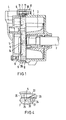
- Fig. 1 is an impeller housing, in which an arranged on a drive shaft 2 impeller 3 is rotatably arranged.
- the drive shaft 2 is net eccentrically with respect to the central axis of the impeller housing 1.
- On the impeller housing 1 is provided with a connection piece 4 to cover 5 and connected by screws 6 to the impeller housing 1.
- a control disk 7 is added.
- the control disk 7 is in turn inserted into a cup-shaped seal 8.
- a radially outwardly projecting bead 10 is formed at the free end of the peripheral wall 9 of the cup-shaped seal 8, a radially outwardly projecting bead 10 is formed. This bead 10 is pressed against the end edge 12 of the impeller housing by an edge 11 of the cover 5 which extends axially over the peripheral wall 9.
- knob-shaped elevations 14 are provided which engage in corresponding recesses 15 of the control disc 7.
- the pot-shaped seal 8 and the control disk 7 are positio ned to each other in their mutual position.
- the cup-shaped seal 8 has a first recess 16 and a second recess 17 in its bottom.
- the first recess 16 is located in the area of the intake manifold and the suction slot and releases access to the medium to be sealed. From the second saving 17, the compressed medium from the pressure slot of the control disk in the letting nozzle can enter.
- a central web 18 located between the two recesses serves to separate the suction formed in the cover and pressure room.
- the knob-shaped elevations 14 are formed on the central web 18. In the central web 18 there are also openings 19 which serve to supply and discharge the operating fluid. These openings 19 coincide with corresponding openings in the control disc 7 and in the cover 5.
- a pin 20 is also formed, which engages in a corresponding opening of a valve plate 21 and a catch plate 22, such as 4 can be seen.
- the valve plate 21 has valve tongues 23 which cover passages 24 provided in the control disk 7.
- the catch plate 22 serves to limit the lifting movement of the valve tongues 23.
- the valve plate 21 becomes through the pin 20, which engages in a corresponding bore 25 in the control disk 7, and through lugs on the catch plate, which engage in recesses in the valve plate and the control disk and the catch plate 22 secured in position.
- the seal is pressed against the catch plate 22 and the valve plate 21 by a rib 26 formed on the cover 5. As a result, these plates are held in their installed position without additional fastening parts being required.
- the cup-shaped seal 8 has on its bottom side facing the cover a support rib 27 which rests against a correspondingly shaped separating rib of the cover 5 lying between the pressure and suction space and thus pushes it away of the central web 18 to the suction side prevented.
- the wall thickness is made weaker on the peripheral wall 9.
- the peripheral wall 9 can be stretched more easily in the axial direction, which is necessary to compensate for length tolerances when installing the pump.
- the thickness of the bottom of the cup-shaped seal 8 can be selected in accordance with the elasticity of the material of the seal so that manufacturing tolerances of the individual parts to be assembled can be compensated for. Since the control disk 7 is largely enclosed by the cup-shaped seal 8, there is also protection against mechanical damage during assembly and disassembly of the control disk.
Landscapes
- Engineering & Computer Science (AREA)
- Mechanical Engineering (AREA)
- General Engineering & Computer Science (AREA)
- Applications Or Details Of Rotary Compressors (AREA)
- Structures Of Non-Positive Displacement Pumps (AREA)
- Fluid-Pressure Circuits (AREA)
Claims (5)
Priority Applications (1)
| Application Number | Priority Date | Filing Date | Title |
|---|---|---|---|
| AT82102023T ATE13934T1 (de) | 1981-03-24 | 1982-03-12 | Fluessigkeitsringpumpe mit einer zwischen einem laufradgehaeuse und einem mit anschlussstutzen versehenen deckel angeordneten steuerscheibe. |
Applications Claiming Priority (2)
| Application Number | Priority Date | Filing Date | Title |
|---|---|---|---|
| DE3111538 | 1981-03-24 | ||
| DE19813111538 DE3111538A1 (de) | 1981-03-24 | 1981-03-24 | Fluessigkeitsringpumpe mit einer zwischen dem laufradgehaeuse und dem mit anschlussstutzen versehenen deckel angeordneten steuerscheibe |
Publications (2)
| Publication Number | Publication Date |
|---|---|
| EP0061626A1 EP0061626A1 (fr) | 1982-10-06 |
| EP0061626B1 true EP0061626B1 (fr) | 1985-06-19 |
Family
ID=6128148
Family Applications (1)
| Application Number | Title | Priority Date | Filing Date |
|---|---|---|---|
| EP82102023A Expired EP0061626B1 (fr) | 1981-03-24 | 1982-03-12 | Pompe à anneau liquide avec disque de commande situé entre un corps de roue et un couvercle muni de connections pour fluide |
Country Status (5)
| Country | Link |
|---|---|
| US (1) | US4443158A (fr) |
| EP (1) | EP0061626B1 (fr) |
| JP (1) | JPS57168083A (fr) |
| AT (1) | ATE13934T1 (fr) |
| DE (2) | DE3111538A1 (fr) |
Families Citing this family (15)
| Publication number | Priority date | Publication date | Assignee | Title |
|---|---|---|---|---|
| DE3337837A1 (de) * | 1983-10-18 | 1985-04-25 | Siemens AG, 1000 Berlin und 8000 München | Fluessigkeitsringpumpe |
| CZ290611B6 (cs) * | 1993-09-23 | 2002-09-11 | Sterling Fluid Systems (Germany) Gmbh | Kapalinokružné plynové čerpadlo |
| DE19727719C1 (de) * | 1997-06-30 | 1998-06-25 | Siemens Ag | Flüssigkeitsringpumpe |
| US6692234B2 (en) * | 1999-03-22 | 2004-02-17 | Water Management Systems | Pump system with vacuum source |
| US6405748B1 (en) * | 1999-03-22 | 2002-06-18 | David Muhs | Trailer and fuel tank assembly |
| US6315524B1 (en) | 1999-03-22 | 2001-11-13 | David Muhs | Pump system with vacuum source |
| US6390768B1 (en) | 1999-03-22 | 2002-05-21 | David Muhs | Pump impeller and related components |
| US6641369B2 (en) * | 1999-05-19 | 2003-11-04 | Robuschi & C. S.P.A. | Liquid ring compressor with thin distribution plate |
| NO318776B1 (no) * | 2003-05-07 | 2005-05-02 | Jets As | Anordning ved vaeskeringspumpe av skruetypen |
| EP1477681B1 (fr) * | 2003-05-16 | 2006-08-23 | Sterling Fluid Systems (Germany) GmbH | Pompe à gaz à anneau liquide |
| US7878768B2 (en) * | 2007-01-19 | 2011-02-01 | David Muhs | Vacuum pump with wear adjustment |
| US20080175722A1 (en) * | 2007-01-19 | 2008-07-24 | David Muhs | Vacuum pump with wear adjustment |
| US8998586B2 (en) * | 2009-08-24 | 2015-04-07 | David Muhs | Self priming pump assembly with a direct drive vacuum pump |
| US9062675B2 (en) | 2012-02-10 | 2015-06-23 | Randy Dixon | Rotary lobe pump with wiper blades |
| JP2023004482A (ja) * | 2021-06-25 | 2023-01-17 | 日本電産トーソク株式会社 | ソレノイドバルブ |
Family Cites Families (8)
| Publication number | Priority date | Publication date | Assignee | Title |
|---|---|---|---|---|
| US2197288A (en) * | 1937-05-27 | 1940-04-16 | Int Harvester Co | Pump |
| US2430426A (en) * | 1943-09-27 | 1947-11-04 | Katcher Morris | Shaft seal and pressure plates and a spring therefor |
| US2672821A (en) * | 1950-08-16 | 1954-03-23 | Gorman Rupp Ind Inc | Centrifugal pump |
| FR1269347A (fr) * | 1960-07-08 | 1961-08-11 | Normacem Sa | Joint d'étanchéité pour liquides |
| US3367682A (en) * | 1964-10-19 | 1968-02-06 | Aerojet General Co | Sealed joint employing pressure loaded and mechanically loaded seal |
| DE2004393C3 (de) * | 1970-01-31 | 1975-06-26 | Siemen & Hinsch Gmbh | Flüssigkeitsrlng-Gaspumpe, deren Pumpengehäuse an ein Gehäuse mit austretendem, angetriebenem Wellenstumpf angeflanscht ist |
| DE2704863A1 (de) * | 1977-02-05 | 1978-08-10 | Kloeckner Humboldt Deutz Ag | Rueckschlagventil fuer eine fluessigkeitsring-gaspumpe |
| GB2064002A (en) * | 1979-11-22 | 1981-06-10 | Graham Precision Pumps Ltd | Liquid Ring Vacuum Pumps |
-
1981
- 1981-03-24 DE DE19813111538 patent/DE3111538A1/de not_active Withdrawn
-
1982
- 1982-03-10 US US06/356,294 patent/US4443158A/en not_active Expired - Lifetime
- 1982-03-12 AT AT82102023T patent/ATE13934T1/de not_active IP Right Cessation
- 1982-03-12 DE DE8282102023T patent/DE3264204D1/de not_active Expired
- 1982-03-12 EP EP82102023A patent/EP0061626B1/fr not_active Expired
- 1982-03-24 JP JP57047069A patent/JPS57168083A/ja active Pending
Also Published As
| Publication number | Publication date |
|---|---|
| US4443158A (en) | 1984-04-17 |
| EP0061626A1 (fr) | 1982-10-06 |
| JPS57168083A (en) | 1982-10-16 |
| DE3264204D1 (en) | 1985-07-25 |
| DE3111538A1 (de) | 1982-10-21 |
| ATE13934T1 (de) | 1985-07-15 |
Similar Documents
| Publication | Publication Date | Title |
|---|---|---|
| EP0061626A1 (fr) | Pompe à anneau liquide avec disque de commande situé entre un corps de roue et un couvercle muni de connections pour fluide | |
| DE69924892T2 (de) | Spiralverdichter mit Auslassventil | |
| DE602004002054T2 (de) | Spiralverdichter mit Auslassventil | |
| DE69102580T2 (de) | Anordnung von vertikal orientierten Kreiselpumpen. | |
| DE112016003236B4 (de) | Scrollverdichter | |
| DE4416077A1 (de) | Flügelzellenpumpe | |
| DE4341148C2 (de) | Spiralverdichter | |
| DE3738686A1 (de) | Spiralkompressor | |
| US6481992B2 (en) | Vane pump | |
| EP2864640A1 (fr) | Pompe centrifuge de moteur pourvue d'une garniture étanche à anneau glissant | |
| DE102025113441A1 (de) | Drehscheibenventil | |
| US4723888A (en) | Pump apparatus | |
| DE3700919A1 (de) | Taumelscheibenkompressor | |
| US3137239A (en) | Pressure loaded pumps | |
| EP0711387B1 (fr) | Pompe a vide comportant un dispositif de ballast de gaz | |
| EP0159968A2 (fr) | Pompe pneumatique à palettes avec carter en tôle métallique estampée | |
| DE1812818C3 (de) | Radialflügelmaschine | |
| DE2555595C2 (de) | Flügelzellenpumpe | |
| US4635675A (en) | Flat sided ball valve | |
| DE8625381U1 (de) | Trockenlaufende Drehschieber-Vakuumpumpe | |
| EP0711386A1 (fr) | Pompe a vide etanche a l'huile | |
| EP0320795A2 (fr) | Pompe à vide avec palettes | |
| US2578780A (en) | Rotary pump seal | |
| DE102020118191A1 (de) | Kältemittelverdichter | |
| EP0758717A1 (fr) | Compresseur à anneau liquide |
Legal Events
| Date | Code | Title | Description |
|---|---|---|---|
| PUAI | Public reference made under article 153(3) epc to a published international application that has entered the european phase |
Free format text: ORIGINAL CODE: 0009012 |
|
| AK | Designated contracting states |
Designated state(s): AT CH DE FR GB IT SE |
|
| 17P | Request for examination filed |
Effective date: 19830224 |
|
| ITF | It: translation for a ep patent filed | ||
| GRAA | (expected) grant |
Free format text: ORIGINAL CODE: 0009210 |
|
| AK | Designated contracting states |
Designated state(s): AT CH DE FR GB IT LI SE |
|
| REF | Corresponds to: |
Ref document number: 13934 Country of ref document: AT Date of ref document: 19850715 Kind code of ref document: T |
|
| REF | Corresponds to: |
Ref document number: 3264204 Country of ref document: DE Date of ref document: 19850725 |
|
| ET | Fr: translation filed | ||
| PLBE | No opposition filed within time limit |
Free format text: ORIGINAL CODE: 0009261 |
|
| STAA | Information on the status of an ep patent application or granted ep patent |
Free format text: STATUS: NO OPPOSITION FILED WITHIN TIME LIMIT |
|
| 26N | No opposition filed | ||
| ITTA | It: last paid annual fee | ||
| EAL | Se: european patent in force in sweden |
Ref document number: 82102023.7 |
|
| PGFP | Annual fee paid to national office [announced via postgrant information from national office to epo] |
Ref country code: GB Payment date: 19970224 Year of fee payment: 16 |
|
| PGFP | Annual fee paid to national office [announced via postgrant information from national office to epo] |
Ref country code: AT Payment date: 19970305 Year of fee payment: 16 |
|
| PGFP | Annual fee paid to national office [announced via postgrant information from national office to epo] |
Ref country code: SE Payment date: 19970321 Year of fee payment: 16 Ref country code: FR Payment date: 19970321 Year of fee payment: 16 |
|
| PGFP | Annual fee paid to national office [announced via postgrant information from national office to epo] |
Ref country code: DE Payment date: 19970521 Year of fee payment: 16 |
|
| PGFP | Annual fee paid to national office [announced via postgrant information from national office to epo] |
Ref country code: CH Payment date: 19970620 Year of fee payment: 16 |
|
| PG25 | Lapsed in a contracting state [announced via postgrant information from national office to epo] |
Ref country code: GB Free format text: LAPSE BECAUSE OF NON-PAYMENT OF DUE FEES Effective date: 19980312 Ref country code: AT Free format text: LAPSE BECAUSE OF NON-PAYMENT OF DUE FEES Effective date: 19980312 |
|
| PG25 | Lapsed in a contracting state [announced via postgrant information from national office to epo] |
Ref country code: SE Free format text: LAPSE BECAUSE OF NON-PAYMENT OF DUE FEES Effective date: 19980313 |
|
| PG25 | Lapsed in a contracting state [announced via postgrant information from national office to epo] |
Ref country code: LI Free format text: LAPSE BECAUSE OF NON-PAYMENT OF DUE FEES Effective date: 19980331 Ref country code: FR Free format text: THE PATENT HAS BEEN ANNULLED BY A DECISION OF A NATIONAL AUTHORITY Effective date: 19980331 Ref country code: CH Free format text: LAPSE BECAUSE OF NON-PAYMENT OF DUE FEES Effective date: 19980331 |
|
| GBPC | Gb: european patent ceased through non-payment of renewal fee |
Effective date: 19980312 |
|
| REG | Reference to a national code |
Ref country code: CH Ref legal event code: PL |
|
| EUG | Se: european patent has lapsed |
Ref document number: 82102023.7 |
|
| REG | Reference to a national code |
Ref country code: FR Ref legal event code: ST |
|
| PG25 | Lapsed in a contracting state [announced via postgrant information from national office to epo] |
Ref country code: DE Free format text: LAPSE BECAUSE OF NON-PAYMENT OF DUE FEES Effective date: 19990101 |