EP0061676A2 - Device for displaying videotext pages, or videotext pages and viewdata pages - Google Patents
Device for displaying videotext pages, or videotext pages and viewdata pages Download PDFInfo
- Publication number
- EP0061676A2 EP0061676A2 EP82102305A EP82102305A EP0061676A2 EP 0061676 A2 EP0061676 A2 EP 0061676A2 EP 82102305 A EP82102305 A EP 82102305A EP 82102305 A EP82102305 A EP 82102305A EP 0061676 A2 EP0061676 A2 EP 0061676A2
- Authority
- EP
- European Patent Office
- Prior art keywords
- page memory
- teletext
- buffer
- decoder
- pages
- Prior art date
- Legal status (The legal status is an assumption and is not a legal conclusion. Google has not performed a legal analysis and makes no representation as to the accuracy of the status listed.)
- Withdrawn
Links
Images

Classifications
-
- H—ELECTRICITY
- H04—ELECTRIC COMMUNICATION TECHNIQUE
- H04N—PICTORIAL COMMUNICATION, e.g. TELEVISION
- H04N21/00—Selective content distribution, e.g. interactive television or video on demand [VOD]
- H04N21/40—Client devices specifically adapted for the reception of or interaction with content, e.g. set-top-box [STB]; Operations thereof
- H04N21/47—End-user applications
- H04N21/488—Data services, e.g. news ticker
- H04N21/4888—Data services, e.g. news ticker for displaying teletext characters
-
- H—ELECTRICITY
- H04—ELECTRIC COMMUNICATION TECHNIQUE
- H04N—PICTORIAL COMMUNICATION, e.g. TELEVISION
- H04N21/00—Selective content distribution, e.g. interactive television or video on demand [VOD]
- H04N21/40—Client devices specifically adapted for the reception of or interaction with content, e.g. set-top-box [STB]; Operations thereof
- H04N21/47—End-user applications
-
- H—ELECTRICITY
- H04—ELECTRIC COMMUNICATION TECHNIQUE
- H04N—PICTORIAL COMMUNICATION, e.g. TELEVISION
- H04N7/00—Television systems
- H04N7/08—Systems for the simultaneous or sequential transmission of more than one television signal, e.g. additional information signals, the signals occupying wholly or partially the same frequency band, e.g. by time division
- H04N7/087—Systems for the simultaneous or sequential transmission of more than one television signal, e.g. additional information signals, the signals occupying wholly or partially the same frequency band, e.g. by time division with signal insertion during the vertical blanking interval only
- H04N7/088—Systems for the simultaneous or sequential transmission of more than one television signal, e.g. additional information signals, the signals occupying wholly or partially the same frequency band, e.g. by time division with signal insertion during the vertical blanking interval only the inserted signal being digital
- H04N7/0882—Systems for the simultaneous or sequential transmission of more than one television signal, e.g. additional information signals, the signals occupying wholly or partially the same frequency band, e.g. by time division with signal insertion during the vertical blanking interval only the inserted signal being digital for the transmission of character code signals, e.g. for teletext
Definitions
- the invention relates to a device according to the wording of the preamble of claim 1.
- the invention is therefore based on the object to provide a device of the type mentioned above with which it is strong Visually impaired or blind people will be able to participate in the new information medium on-screen text and / or teletext.
- An advantage of the invention is to be seen in the fact that televisions equipped with a teletext or teletext screen text decoder have no particular difficulties, i. H. can be converted without any major changes to the components present in the television sets. Another advantage is that the reproduction of information on the screen of a television set is not disturbed by the reproduction of information on the Braille display. It is also advantageous that the application is not limited to television sets. Rather, a teletext or teletext screen text decoder having receiving components, such as. B. VCR can be used.
- the components of a teletext or teletext screen text decoder are shown in a dashed box representing a television set 1, which enables the playback of teletext or teletext and screen text on the screen of the television set 1.
- These components are a decoder 2, a page memory 3 connected downstream of the decoder and a character generator 4 which is fed by the page memory 3.
- the character generator 4 is connected upstream of the screen of the television set 1, which is not shown in the drawing.
- the page memory 3 has a buffer page memory 5 connected in parallel, which can be arranged inside the television set housing.
- the buffer page memory 5 is connected to an external control panel 6, which has a control circuit arrangement, a Braille line for line-by-line output of the text pages and an operating keyboard for entering operating functions.
- the Braille line can be one with 40 digits. For safety reasons, electrical isolation is provided between the buffer page memory 5 and the control panel 6.
- a buffer memory is arranged in the control panel 6. This ensures that the playback on the screen is not disturbed by the information playback on the Braille line contained in the control panel 6.
- the automatic output of user guidance information enables easy handling of the system. For example, after reading the screen text or teletext page, the message "Please request a new page" is output automatically.
- a visually impaired or blind person can, for example, do the following via the control keyboard of the control panel 6
- the control panel 6 has a keyboard 9 for entering operating functions, a processor 10 downstream of the keyboard 9, and a control circuit arrangement 11 connected to the output of the processor 10, which controls a Braille line 12.
- a power supply unit 13 of known type supplies the processor 10 and the circuit arrangement 11 with the required electrical energy.
- the processor unit 15 then controls the control circuit arrangement shown in FIG. 4 for the Braille line by means of a program via the module 17 with associated outputs 24 and 25. Via the combination module 18 and the module 19, address, select and clock signals are output to the buffer memory 5 (shown in FIG. 5) with the aid of the output 23 and the content of the page memory is read in via the module 20 with the associated input 22.
- the control circuit arrangement from FIG. 4 has a module 26, the input of which is connected to the output 24 of the module 17 from FIG. 3 and which is followed by a multiplex circuit arrangement 27 and a device for module selection 28. These components serve to select the modules of the Braille line 29.
- the Braille line 29 has forty modules, each of which is intended for six pens.
- the module 26 serves as a driver for decoupling the multiplex circuit arrangement 27, which, for. B. may consist of block 74 LS 138 and five blocks 7445 indicated in the drawing. One 7445 block is responsible for the selection of eight modules each.
- the outputs of the modules 7445 which are put into operation by the module 74 LS 138, control for example forty PNP Darlington circuit arrangements BD 680 in the device for module selection 28, by means of which the coils of the styli of the Braille display 29 are supplied with electrical energy .
- the styli of Braille line 29 are selected by a matrix that has 12 x 40 elements.
- the number 12 results from the number of pins for a module (six) and the positions "Set” and “Delete” (two) for the stylus.
- the number 40 is determined by the number of modules used (forty).
- the circuit arrangement for the "set” and “delete” positions of the pins is connected to the output 25 of the module 17 from FIG. 3.
- This circuit arrangement has a signal setting path with the electronic component 30 and the setting driver 31 and a signal erasing path with the electronic components 32 and 33 and the erasing driver 34. Both signal paths are routed to Braille display 29.
- the position of the styli is determined by a 6-bit word, where logic "I" corresponds to "set” and logic "O” to "delete”. Since it is not possible to set or delete the six pins of a module at the same time, only three pins are activated at a time. These are either pins 1, 5, 3 or 4, 2, 6. This and the switching off of the module is implemented by two operating lines 35 and 36, two additional bits of which are required to control them.
- the buffer page memory shown in FIG. 5 has two optocoupler blocks 37 and 38 which are connected to the inputs and outputs 22 and 23 of the modules 20 and 19 from FIG.
- the outputs of the optocoupler block 38 are connected via an integrated module 39 to a decoder 40, which is followed by a multiplexer 41 with a secondary buffer 42.
- the multiplexer 41 has three integrated circuits IC 13, 14 and 15.
- the decoder 2 from FIGS. 1 and 2 supplies the multiplexer 41 with further signals, which are also input to the image repetition memory 43.
- the buffer page memory further has two electronic components 44 and 45, of which the component 45 is connected to the inputs of the Dptocoupler block 37. Component 44 serves to decouple component 42 from decoder 2.
Landscapes
- Engineering & Computer Science (AREA)
- Multimedia (AREA)
- Signal Processing (AREA)
- Television Systems (AREA)
- Controls And Circuits For Display Device (AREA)
Abstract
Gerät zur Wiedergabe von Videotextseiten oder von Videotext- und Bildschirmtextseiten unter Verwendung eines einen Videotext- bzw. Videotext-Bildschirmtext-Dekoder aufweisenden Empfangsbauteiles, insbesondere eines Fernsehgerätes. Der Dekoder weist einen Seitenspeicher und einen dem Seitenspeicher nachgeschalteten Zeichengenerator auf. Zum Seitenspeicher ist ein Pufferseitenspeicher logisch parallel geschaltet, der mit einem von einem Blinden bedienbaren Bedienpult zusammenwirkt. Das Bedienpult weist eine Ansteuerschaltungsanordnung, eine Braille-Zeile zur zeilenweisen Ausgabe der Textseiten und eine Bedienungstastatur zur Eingabe von Bedienungsfunktionen auf. Gegebenenfalls ist der Pufferseitenspeicher von dem Seitenspeicher abkoppelbar. Nach einem Abkoppelvorgang wird der von dem Seitenspeicher an den Pufferseitenspeicher gelieferte Textinhalt in den Seitenspeicher des Pufferseitenspeichers aufgenommen. Nach Aufnahme des Textinhaltes wird der Pufferseitenspeicher wieder parallel zum Seitenspeicher angekoppelt.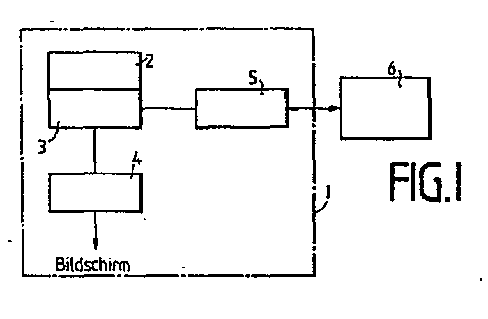
Description
Die Erfindung bezieht sich auf ein Gerät gemäß dem Wortlaut des Oberbegriffes von Anspruch 1.The invention relates to a device according to the wording of the preamble of
,Es ist allgemein bekannt, auf dem Bildschirm eines Fernsehgerätes Videotext- oder Bildschirmtextseiten wiederzugeben, wobei gerade in letzter Zeit in mehreren europäischen Ländern Bestrebungen im Gange sind, den Bildschirmtext in größerem Umfang einzuführen. Um dieses zu verwirklichen, ist es erforderlich, neu auf den Markt kommende Fernsehgeräte mit einem Videotext- bzw. Videotext-Bildschirmtext-Dekoder auszurüsten bzw. bereits vorhandene Fernsehgeräte mit einem derartigen Dekoder nachzurüsten. Nachteilig ist allerdings, daß die bisher vorhandenen Geräte nur für sehende Personen, nicht jedoch für stark Sehbehinderte oder Blinde verwendet werden können.It is generally known to display teletext or screen text pages on the screen of a television, although efforts have recently been made in a number of European countries to introduce the screen text on a larger scale. In order to achieve this, it is necessary to equip new televisions coming onto the market with a teletext or teletext screen text decoder or to retrofit existing televisions with such a decoder. It is disadvantageous, however, that the devices available hitherto can only be used for sighted people, but not for the visually impaired or blind.
Der Erfindung liegt daher die Aufgabe zugrunde, ein Gerät der eingangs genannten Art zu schaffen, mit dem es stark Sehbehinderten oder Blinden ermöglicht wird, an dem neuen Informationsmedium Bildschirmtext und/oder Videotext teilhaben zu können.The invention is therefore based on the object to provide a device of the type mentioned above with which it is strong Visually impaired or blind people will be able to participate in the new information medium on-screen text and / or teletext.
Die Aufgabe wird erfindungsgemäß durch die kennzeichnenden Merkmale vôn Anspruch 1 gelöst.The object is achieved by the characterizing features of
Ausgestaltungen der Erfindung sind in den Unteransprüchen 2 bis 8 beschrieben.Embodiments of the invention are described in
Ein Vorteil der Erfindung ist darin zu sehen, daß mit einem Videotext- bzw. Videotext-Bildschirmtext-Dekoder ausgerüstete Fernsehgeräte ohne besondere Schwierigkeiten, d. h. ohne irgendwelche großen Veränderungen an in den Fernsehgeräten vorhandenen Bauelementen umgerüstet werden können. Ein weiterer Vorteil liegt darin, daß die Informationswiedergabe auf dem Bildschirm eines Fernsehgerätes durch die Informations-Wiedergabe auf der Braille-Zeile nicht gestört wird. Vorteilhaft ist es auch, daß die Anwendung nicht auf Fernsehgeräte beschränkt ist. Vielmehr können auch einen Videotext- bzw. Videotext-Bildschirmtext-Dekoder aufweisende Empfangsbauteile, wie z. B. Videorecorder verwendet werden.An advantage of the invention is to be seen in the fact that televisions equipped with a teletext or teletext screen text decoder have no particular difficulties, i. H. can be converted without any major changes to the components present in the television sets. Another advantage is that the reproduction of information on the screen of a television set is not disturbed by the reproduction of information on the Braille display. It is also advantageous that the application is not limited to television sets. Rather, a teletext or teletext screen text decoder having receiving components, such as. B. VCR can be used.
In der Zeichnung ist ein Ausführungsbeispiel nach der Erfindung dargestellt, und zwar zeigt:
- Fig. 1 und 2 jeweils ein Blockschaltbild eines ein Fernsehgerät verwendendes Gerätes,
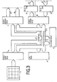
- Fig. 3 die Bedientastatur mit zugehörender Schaltungsanordnung des Bedienpultes,
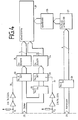
- Fig. 4 die Ansteuerschaltungsanordnung für die Braille- zeile und
- Fig. 5 das Schaltbild eines Pufferseitenspeichers (Seitenspeicherinterface).
- 1 and 2 are each a block diagram of a device using a television set,
- 3 the control keyboard with associated circuitry of the control panel,
- 4 shows the control circuit arrangement for the Braille display and
- 5 shows the circuit diagram of a buffer page memory (page memory interface).
In dem Blockschaltbild sind in einem gestrichelt gezeichneten, ein Fernsehgerät 1 darstellenden Kasten die Bauelemente eines Videotext- bzw. Videotext-Bildschirmtext-Dekoders dargestellt, der die Wiedergabe von Videotext bzw. Videotext und Bildschirmtext auf dem Bildschirm des Fernsehgerätes 1 ermöglicht. Diese Bauelemente sind ein Dekoder 2, ein dem Dekoder nachgeschalteter Seitenspeicher 3 und ein Zeichengenerator 4, der von dem Seitenspeicher 3 gespeist wird. Der Zeichengenerator 4 ist dem zeichnerisch nicht dargestellten Bildschirm des Fernsehgerätes 1 vorgeschaltet. Um dieses Gerät 1 für die Benutzung durch stark Sehbehinderte oder Blinde umzurüsten, ist dem Seitenspeicher 3 ein Pufferseitenspeicher 5 parallel geschaltet, der innerhalb des Fernsehgerätegehäuses angeordnet werden kann. Der Pufferseitenspeicher 5 ist an ein externes Bedienpult 6 angeschlossen, das eine Ansteuer- schaltungsanordnung, eine Braille-Zeile zur zeilenweisen Ausgabe der Textseiten und eine Bedientastatur zur Eingabe von Bedienungsfunktionen aufweist. Bei der Braille-Zeile kann es sich um eine solche mit 40 Stellen handeln. Aus Sicherheitsgründen ist zwischen dem Pufferseitenspeicher 5 und dem Bedienpult 6 eine galvanische Trennung vorgesehen.In the block diagram, the components of a teletext or teletext screen text decoder are shown in a dashed box representing a
Im Bedienpult 6 ist ein Pufferspeicher angeordnet. Hierbei ist sichergestellt, daß die Wiedergabe auf dem Bildschirm durch die Informationswiedergabe auf der im Bedienpult 6 enthaltenen Braille-Zeile nicht gestört wird. Die automatische Ausgabe von Informationen zur Benutzerführung ermöglicht eine einfache Handhabung der Anlage. Beispielsweise wird nach dem Lesen der Bildschirmtext- bzw. Videotextseite die Meldung "bitte neue Seite anfordern" automatisch ausgegeben.A buffer memory is arranged in the
Über die Bedienungstastatur des Bedienpultes 6 kann eine sehbehinderte oder blinde Person beispielsweise folgendeA visually impaired or blind person can, for example, do the following via the control keyboard of the
Bedienungsfunktionen dem Gerät eingeben:
- .1. Übernahme einer Seite auf den Bildschirm,
- 2. Ausgabe der vorhergehenden oder folgenden Textzeile
- 3. Nochmalige Wiedergabe einer Zeile,
- 4. Einstellung auf erste Zeile (Anfang der Seite),
- 5. Einstellung auf letzte Zeile (Ende der Seite),
- 6. Direkte Anwahl einer Zeile (Zeilen-Nummern eingeben),
- 7. Ausgabe der laufenden (gerade gelesenen) Zeilen-Nummer,
- 8. Wiedergabe eines Sonderzeichens für Leerstellen, d. h. für Stellen, die nicht darstellbare Zeichen enthalten (z.B. graphische Darstellungen).
- .1. Transfer of a page to the screen,
- 2. Output of the previous or following line of text
- 3. Repeat playback of a line,
- 4. Setting to the first line (top of the page),
- 5. Setting to the last line (bottom of the page),
- 6. Direct selection of a line (enter line numbers),
- 7. Output of the current (just read) line number,
- 8. Reproduction of a special character for spaces, ie for positions that contain characters that cannot be displayed (eg graphical representations).
Bei dem in Figur 2 dargestellten Gerät sind für die einzelnen Bauelemente, die mit denen aus Figur 1 übereinstimmen, dieselben Bezugszeichen wie in Figur 1 verwendet worden. Der mit 2 bezeichnete Dekoder enthält auch die zeichnerisch nicht dargestellten Seitenspeicher und Zeichengenerator. Bei dem Dekoder kann es sich um einen Ualvo-Uideo-Text-Dekoder der Firma Ualvo/ Deutschland handeln, der ebenfalls in dem in Figur 1 dargestellten Gerät zur Anwendung kommen kann. Dieser Dekoder besteht im wesentlichen aus den vier LSI-Schaltungen
- - SAA 5020 Taktsteuerung
- - SAA 5030 Uideoprozessor
- - SAA 5041 Datenverarbeitungs- und Steuerschaltung
- - SAA 5051 Zeichengenerator sowie zwei Standard-Speicherschaltungen 2614 (statische 1 k x 4 - RAMs) für den Seitenspeicher. An den Dekoder ist ein allgemein bekanntes Netzschaltungsteil 7 angeschlossen. Der Monitor des Fernsehgerätes ist - im Gegensatz zu Figur 1 - zeichnerisch dargestellt und
mit 8 bezeichnet. Durch den zeichnerisch besonders hervorgehobenen Monitor 7 wird auch verdeutlicht, daß der Dekoder 2mit zugehörendem Seitenspeicher 3, Zeichengenerator 4 und Netzteil 7 sowie der Pufferseitenspeicher 5 jeweils als ein Zusatzgerät ausgeführt und als solche an bereits vorhandene Fernsehgeräte angeschlossen werden können.
- - SAA 5020 clock control
- - SAA 5030 Uideoprocessor
- - SAA 5041 data processing and control circuit
- - SAA 5051 character generator and two standard memory circuits 2614 (static 1 kx 4 RAMs) for the page memory. A generally known network circuit part 7 is connected to the decoder. In contrast to FIG. 1, the monitor of the television set is shown in the drawing and labeled 8. By the Monitor 7, which is particularly emphasized in the drawing, also clarifies that the
decoder 2 with associatedpage memory 3, character generator 4 and power supply unit 7 and thebuffer page memory 5 can each be designed as an additional device and can be connected as such to existing television sets.
Das Bedienpult 6 weist eine Tastatur 9 zur Eingabe von Bedienungsfunktionen, einen der Tastatur 9 nachgeordneten Prozessor 10, und eine an dem Ausgang des Prozessors 10 angeschlossene Ansteuer-Schaltungsanordnung 11 auf, die eine Braille-Zeile 12 ansteuert. Ein Netzgerät 13 bekannter Art versorgt den Prozessor 10 und die Schaltungsanordnung 11 mit der benötigten elektrischen Energie.The
Einzelheiten der Schaltungsanordnung, die der .Bedientastatur 9 des Bedienpultes 6 nachgeordnet ist, sind in Figur 3 dargestellt. Die Schaltungsanordnung besteht im wesentlichen aus dem PORT/RAM-Baustein 14, der Prozessoreinheit 15, dem RAM-Baustein 16, den PORT/EPROM-Bausteinen 17 und 18 sowie den Bausteinen 19 und 20 und zugehörenden Steuer-, Adress-und Datensammelschienen 21 und 21a. Das Programm für die Prozessoreinheit 15 wird in den Kombi-Bausteinen 17 und 18 abgespeichert. Die von dem in den Figuren 1 und 2 mit 5 bezeichneten Pufferseitenspeicher, der in Figur 5 ausführlich dargestellt ist und an dem Eingang 22 des Bausteines 20 und dem Ausgang 23 des Bausteines 19 angeschlossen ist, übernommenen Daten werden in dem Baustein 16 abgelegt. Gesteuert wird die Schaltungsanordnung über die Bedientastatur 9, mit der beispielsweise folgende Funktionen ausgelöst werden:
- 1. Seite einlesen und mit erster Zeile ausgeben,
- 2. Zeile vorwärts ausgeben,
- 3. Zeile rückwärts ausgeben,
- 4. gleiche Zeile nochmals ausgeben,
- 5.
auf Zeile 24 springen und - 6.
auf Zeile 1 springen.
- 1. Read page and output with first line,
- Output 2nd line forward,
- Output 3rd line backwards
- 4. output the same line again,
- 5. jump to
line 24 and - 6. jump to
line 1.
Die Prozessoreinheit 15 steuert dann mittels Programm über den Baustein 17 mit zugehörenden Ausgängen 24 und 25 die in Figur 4 dargestellte Ansteuerschaltungsanordn=ung für die Braille-Zeile an. Über den Kombi-Baustein 18 und den Baustein 19 werden mit Hilfe des Ausganges 23 Adress-, Select- und Clocksignale an den Pufferspeicher 5 (in Figur 5 dargestellt) ausgegeben und über den Baustein 20 mit zugehörendem Eingang 22 der Inhalt des Seitenspeichers eingelesen.The
Die Ansteuerschaltungsanordnung aus Figur 4 weist einen Baustein 26 auf, dessen Eingang an dem Ausgang 24 des Bausteines 17 aus Figur 3 angeschlossen ist und dem eine Multiplexschaltungsanordnung 27 und eine Einrichtung zur Modulauswahl 28 nachgeschaltet sind. Diese Bauelemente dienen dazu, die Module der Braille-Zeile 29 auszuwählen. Die Braille-Zeile 29 weist vierzig Module auf, die jeweils für sechs Stifte vorgesehen sind. Bei der Auswahl der Module dient der Baustein 26 als Treiber zur Entkopplung der Multiplexschaltungsanordnung 27, die z. B. aus in der Zeichnung angegebenem Baustein 74 LS 138 und fünf Bausteinen 7445 bestehen kann. Jeweils ein Baustein 7445 ist für die Auswahl von je acht Modulen zuständig. Die Ausgänge der Bausteine 7445, die von dem Baustein 74 LS 138 in Betrieb gesetzt werden, steuern beispielsweise vierzig PNP-Darlington-Schaltungsanordnungen BD 680 in der Einrichtung zur Modulauswahl 28 an, durch die die Spulen der Taststifte der Braillezeile 29 mit elektrischer Energie versorgt werden.The control circuit arrangement from FIG. 4 has a
Die Taststifte der Braille-Zeile 29 werden durch eine Matrix angewählt, die 12 x 40 Elemente besitzt. Die Zahl 12 ergibt sich aus der Anzahl der Stifte für ein Modul (sechs) und den Positionen "Setzen" und "Löschen" (zwei) für die Taststifte. Die Zahl 40 ist durch die Anzahl der verwendeten Module (vierzig) festgelegt.The styli of
Die Schaltungsanordnung für die Positionen "Setzen" und "Löschen" der Stifte ist am Ausgang 25 des Bausteines 17 aus Figur 3 angeschlossen. Diese Schaltungsanordnung weist einen Signalsetzweg mit dem elektronischen Baustein 30 und dem Setztreiber 31 sowie einen Signallöschweg mit den elektronischen Bausteinen 32 und 33 und dem Löschtreiber 34 auf. Beide Signalwege sind an die Braillezeile 29 geführt. Die Position der Taststifte wird durch ein 6-bit-Wort bestimmt, wobei logisch "I" dem "Setzen" und logisch "O" dem "Löschen" entspricht. Da es nicht möglich ist, die sechs Stifte eines Moduls gleichzeitig zu setzen oder zu löschen, werden jeweils nur drei Stifte zur gleichen Zeit angesteuert. Es sind dies entweder die Stifte 1, 5, 3 oder 4, 2, 6. Dieses und die Abschaltung des Moduls wird durch zwei Betriebs-Leitungen 35 und 36 realisiert, zu deren Ansteuerung zwei weitere Bits benötigt werden.The circuit arrangement for the "set" and "delete" positions of the pins is connected to the
Der in Figur 5 dargestellte Pufferseitenspeicher weist zwei Optokopplerblöcke 37 und 38 auf, die an den Ein- bzw. Ausgang 22 bzw. 23 der Bausteine 20 bzw. 19 aus Figur 3 angeschlossen sind. Die Ausgänge des Optokopplerblocks 38 sind über einen integrierten Baustein 39 an einen Dekoder 40 angeschlossen, dem ein Multiplexer 41 mit nachgeordnetem Zwischenspeicher 42 nachgeschaltet ist. Der Multiplexer 41 weist drei integrierte Schaltkreise IC 13, 14 und 15 auf. Dem Multiplexer 41 werden von dem Dekoder 2 aus den Figuren 1 und 2 weitere Signale zugeführt, die auch dem Bildwiederholspeicher 43 eingegeben werden. Der Pufferseitenspeicher weist weiterhin zwei elektronische Bauelemente 44 und 45 auf, von denen der Baustein 45 an die Eingänge des Dptokopplerblocks 37 angeschlossen ist. Bauelement 44 dient zur Entkopplung des Bauelementes 42 vom Dekoder 2.The buffer page memory shown in FIG. 5 has two optocoupler blocks 37 and 38 which are connected to the inputs and outputs 22 and 23 of the
Die über die Anschlüsse P1 und P2 von dem Dekoder 2 direkt an den Pufferseitenspeicher 5 geführten Daten werden in dem Bildwiederholspeicher 43 (IC 19/20) und über den elektronischen Baustein 44 (IC 18) in dem Zwischenspeicher 42 (IC 16/17) gespeichert. Die als Bildwiederhalspeicher dienenden IC 19 und IC 20 werden von dem Bildschirmtext-Dekoder 2 angesteuert. Die als Zwischenspeicher für das Bedienpult 6 dienenden IC 16 und 17 werden wie folgt ausgelesen:
- Über den Optokopplerblock 38 (
IC 1 bis IC 4), den Baustein 39 (IC 9) und den Dekoder (IC 11 und IC 12) werden die Adressen an den Zwischenspeicher 42 (IC 16 und IC 17) angelegt, nachdem der Multiplexer 41 (IC 13, IC 14 und IC 15) von einem Signal umgeschaltet worden ist. Dieses Signal kann über dem Optokopplerblock 38, beispielsweisevon dem IC 1, bereitgestellt werden. Über den Baustein 45 (IC 10) und den Optokoppler 37 (IC 5 bis IC 8) werden die Daten andas Bedienpult 6 übergeben. Somit dient der Dekoder 40 (IC 11 und IC 12) zur Umrechnung und Abspeicherung der gemultiplexten Adressen.
- Via the optocoupler block 38 (
IC 1 to IC 4), the component 39 (IC 9) and the decoder (IC 11 and IC 12), the addresses are applied to the buffer store 42 (IC 16 and IC 17) after the multiplexer 41 ( IC 13, IC 14 and IC 15) has been switched by a signal. This signal can be provided via the optocoupler block 38, for example by theIC 1. The data are transferred to thecontrol panel 6 via the module 45 (IC 10) and the optocoupler 37 (IC 5 to IC 8). Thus, the decoder 40 (IC 11 and IC 12) is used to convert and store the multiplexed addresses.
Claims (9)
Applications Claiming Priority (2)
| Application Number | Priority Date | Filing Date | Title |
|---|---|---|---|
| DE3112438A DE3112438C2 (en) | 1981-03-28 | 1981-03-28 | Device for displaying teletext pages and / or teletext pages for the visually impaired or blind |
| DE3112438 | 1981-03-28 |
Publications (2)
| Publication Number | Publication Date |
|---|---|
| EP0061676A2 true EP0061676A2 (en) | 1982-10-06 |
| EP0061676A3 EP0061676A3 (en) | 1982-12-08 |
Family
ID=6128648
Family Applications (1)
| Application Number | Title | Priority Date | Filing Date |
|---|---|---|---|
| EP82102305A Withdrawn EP0061676A3 (en) | 1981-03-28 | 1982-03-20 | Device for displaying videotext pages, or videotext pages and viewdata pages |
Country Status (2)
| Country | Link |
|---|---|
| EP (1) | EP0061676A3 (en) |
| DE (1) | DE3112438C2 (en) |
Cited By (1)
| Publication number | Priority date | Publication date | Assignee | Title |
|---|---|---|---|---|
| EP0151712A1 (en) * | 1984-01-03 | 1985-08-21 | Siemens Nixdorf Informationssysteme Aktiengesellschaft | Displaying arrangement of information on a reader for blind people |
Families Citing this family (1)
| Publication number | Priority date | Publication date | Assignee | Title |
|---|---|---|---|---|
| DE3527065A1 (en) * | 1985-07-29 | 1987-02-05 | Werner Prof Dr Boldt | Method for the tactile representation of the breakdown structure of text and graphics pages for use with line output of the text in Braille or synthetic speech |
Family Cites Families (4)
| Publication number | Priority date | Publication date | Assignee | Title |
|---|---|---|---|---|
| DE2355538A1 (en) * | 1972-11-09 | 1974-05-16 | Telub Ab | Facility for the conversion of information for the purpose of perception by the visually impaired |
| DE2760394C2 (en) * | 1976-09-06 | 1988-12-22 | Etablissement Public De Diffusion Dit "Telediffusion De France", Montrouge, Fr | |
| DE2657064C2 (en) * | 1976-12-14 | 1985-03-07 | Heinrich-Hertz-Institut für Nachrichtentechnik Berlin GmbH, 1000 Berlin | Method of recording and reproducing Braille using magnetic tape |
| DE2823175A1 (en) * | 1978-05-27 | 1979-11-29 | Itt Ind Gmbh Deutsche | DISPLAY DEVICE FOR TELETEXT CHARACTERS |
-
1981
- 1981-03-28 DE DE3112438A patent/DE3112438C2/en not_active Expired
-
1982
- 1982-03-20 EP EP82102305A patent/EP0061676A3/en not_active Withdrawn
Cited By (1)
| Publication number | Priority date | Publication date | Assignee | Title |
|---|---|---|---|---|
| EP0151712A1 (en) * | 1984-01-03 | 1985-08-21 | Siemens Nixdorf Informationssysteme Aktiengesellschaft | Displaying arrangement of information on a reader for blind people |
Also Published As
| Publication number | Publication date |
|---|---|
| DE3112438A1 (en) | 1982-10-14 |
| EP0061676A3 (en) | 1982-12-08 |
| DE3112438C2 (en) | 1983-02-03 |
Similar Documents
| Publication | Publication Date | Title |
|---|---|---|
| EP0113022B1 (en) | Videotext system with public terminals | |
| DE3346458C2 (en) | ||
| DE2740009A1 (en) | DEVICE FOR CONTROLLING INFORMATION THAT IS TO BE DISPLAYED ON A TELEVISION DEVICE | |
| DE2753063A1 (en) | STORAGE WORK | |
| DE3514821A1 (en) | Display control circuit for controlling at least two different display devices | |
| DE3714172A1 (en) | DEVICE FOR BROWSING DOCUMENTS IN A DOCUMENT FILING SYSTEM | |
| DE2747498C2 (en) | Arrangement for capturing and storing signatures | |
| EP0090292A2 (en) | Combination of entertainment electronics devices including a television receiver, a video recorder and/or a playback apparatus | |
| DE3425022A1 (en) | CIRCUIT ARRANGEMENT FOR DISPLAYING IMAGES IN DIFFERENT AREAS OF AN IMAGE FIELD | |
| DE2261141C3 (en) | Device for the graphic representation of data contained in a computer | |
| DE3421725A1 (en) | COLOR SIGNAL CONVERTER SWITCHING | |
| DE3334117A1 (en) | Method for inputting information items for process control with the aid of an input display interacting with an input pen | |
| DE2607842C2 (en) | ||
| DE2651543A1 (en) | DIGITAL GRID DISPLAY SYSTEM | |
| DE2223332A1 (en) | Device for the visible display of data on a playback device | |
| DE3428237A1 (en) | Arrangement for setting different communication services in a communication device | |
| DE2920227A1 (en) | PROCESSOR FOR RECORDER END STATIONS | |
| DE3723590A1 (en) | SINGLE IMAGE COMPOSITION WITH COLOR SEARCH TABLE | |
| DE68917670T2 (en) | Teletext decoder. | |
| DE2213953B2 (en) | Line raster visual display control circuit - has generator containing character signals as matrix of lines and columns of points which are intensity scanned | |
| EP0061676A2 (en) | Device for displaying videotext pages, or videotext pages and viewdata pages | |
| DE3811148A1 (en) | DATA PROCESSING DEVICE WITH A MEMORY CONTROL FUNCTION | |
| DE3750003T2 (en) | Display control device with improved attribute function. | |
| DE3046972C2 (en) | Control circuit for generating dot pattern data | |
| DE1801381C3 (en) | Data display device for displaying characters in rows on a screen |
Legal Events
| Date | Code | Title | Description |
|---|---|---|---|
| PUAI | Public reference made under article 153(3) epc to a published international application that has entered the european phase |
Free format text: ORIGINAL CODE: 0009012 |
|
| AK | Designated contracting states |
Designated state(s): AT GB NL SE |
|
| PUAL | Search report despatched |
Free format text: ORIGINAL CODE: 0009013 |
|
| AK | Designated contracting states |
Designated state(s): AT GB NL SE |
|
| STAA | Information on the status of an ep patent application or granted ep patent |
Free format text: STATUS: THE APPLICATION IS DEEMED TO BE WITHDRAWN |
|
| 18D | Application deemed to be withdrawn |
Effective date: 19831112 |
|
| RIN1 | Information on inventor provided before grant (corrected) |
Inventor name: GREEN, HARTMUT, DIPL.-ING. Inventor name: KOLZENBURG, ULRICH, DIPL.-ING. Inventor name: LIMMER, LOTHAR, DIPL.-ING. Inventor name: WELLHAUSEN, LUTZ, DIPL.-ING. Inventor name: MARBURG, HELMUT, ING. GRAD. |