EP0061719A1 - Vorrichtung zur Erhöhung der Bestrahlungsleistung eines Laserbündels - Google Patents
Vorrichtung zur Erhöhung der Bestrahlungsleistung eines Laserbündels Download PDFInfo
- Publication number
- EP0061719A1 EP0061719A1 EP82102471A EP82102471A EP0061719A1 EP 0061719 A1 EP0061719 A1 EP 0061719A1 EP 82102471 A EP82102471 A EP 82102471A EP 82102471 A EP82102471 A EP 82102471A EP 0061719 A1 EP0061719 A1 EP 0061719A1
- Authority
- EP
- European Patent Office
- Prior art keywords
- transducer
- mirror
- rod
- reflecting surface
- movement
- Prior art date
- Legal status (The legal status is an assumption and is not a legal conclusion. Google has not performed a legal analysis and makes no representation as to the accuracy of the status listed.)
- Granted
Links
- 230000005855 radiation Effects 0.000 title 1
- 238000005286 illumination Methods 0.000 claims abstract description 7
- 239000003638 chemical reducing agent Substances 0.000 claims abstract description 6
- 238000006073 displacement reaction Methods 0.000 claims description 15
- 230000001131 transforming effect Effects 0.000 claims description 2
- 230000007547 defect Effects 0.000 description 3
- 239000007788 liquid Substances 0.000 description 2
- 230000003416 augmentation Effects 0.000 description 1
- 230000006835 compression Effects 0.000 description 1
- 238000007906 compression Methods 0.000 description 1
- 230000000694 effects Effects 0.000 description 1
- 235000021183 entrée Nutrition 0.000 description 1
- 230000005284 excitation Effects 0.000 description 1
- 239000012530 fluid Substances 0.000 description 1
- 230000009931 harmful effect Effects 0.000 description 1
- 239000012528 membrane Substances 0.000 description 1
- 239000002184 metal Substances 0.000 description 1
- 230000010287 polarization Effects 0.000 description 1
- 230000001902 propagating effect Effects 0.000 description 1
- 230000003068 static effect Effects 0.000 description 1
Images
Classifications
-
- G—PHYSICS
- G02—OPTICS
- G02B—OPTICAL ELEMENTS, SYSTEMS OR APPARATUS
- G02B26/00—Optical devices or arrangements for the control of light using movable or deformable optical elements
- G02B26/06—Optical devices or arrangements for the control of light using movable or deformable optical elements for controlling the phase of light
Definitions
- the present invention relates to a device for increasing the illumination produced by a laser beam.
- the wave front of a laser beam can have static or dynamic flatness defects.
- a laser beam propagating towards a target can be affected by phase distortions caused for example by atmospheric turbulence. These defects and these distortions cause a reduction in lighting.
- a known device for increasing the illumination produced by a laser beam on a target comprises a mirror with a reflected surface .
- deformable chissant capable of reflecting a laser beam towards a target
- a photoelectric receiver capable of detecting the energy of the beam reflected by the target
- a processing circuit connected to the output of the receiver and a plurality of piezoelectric elements fixed with a on the surface of the mirror and on the other hand on a rigid plate, the electrodes of the piezoelectric elements being connected to the output of the processing circuit.
- the processing circuit delivers polarization signals from the electrodes so as to cause a deformation of the reflecting surface of the mirror. This deformation corrects the wavefront of the beam reflected by the mirror, so as to increase the energy detected by the receiver.
- the known device described above has a drawback: in certain applications, it is difficult to obtain mirror deformations of suitable amplitude.
- the object of the present invention is to produce a new device of this type, making it possible to more easily adapt the amplitudes of deformation of the mirror to the different application conditions which may arise.
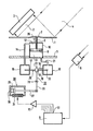
- a mirror comprising a polished metal sheet 1 reflects a beam 2 emitted by a laser generator 3.
- the reflected beam 4 is directed towards a target not shown.
- the target returns part of the beam 4 to a photoelectric receiver 5 connected to the input of a processing circuit 6.
- the outer wall of the cylinder 10 is secured to a rigid plate 11 substantially parallel to the surface 1.
- the piston 9 divides the internal volume of the cylinder 10 into two parts 12 and 13.
- the part 12, located on the side of the bar 8, is in communication by a pipe 14 with the internal volume of a reservoir 15.
- a rod 16 passes through the wall of the reservoir 15 through an orifice 17, so that one end of the rod 16 is located in the reservoir 15.
- the rod 16 also passes through the wall of another reservoir 18 through an orifice 19, so that the another end 20 of the rod 15 is located in the reservoir 18.
- a pipe 21 places the internal volume of the reservoir 18 in communication with the other part 13 of the internal volume of the cylinder 10.
- One end 22 of a lever 23 is introduced into a rotary sleeve 24 fixed on the rod 16 substantially in the middle of its length.
- the other end 26 of the lever 23 mounted in rotation about a fixed axis 25, is articulated on the plunger core 27 of an electromagnet 28.
- a helical spring 29 is inserted between the end of the core 27 and the armature 30 of the electromagnet.
- the excitation coil 31 of the electromagnet 28 is connected to an output 32 of the processing circuit 6 through a power amplifier 33.
- the tanks 15 and 18, the pipes 14 and 21 as well as the parts 12 and 13 of the internal volume of the cylinder 10 are filled with a hydraulic liquid.
- the device comprises in practice a plurality of cylinders identical to the cylinder 10, these cylinders being fixed on the plate 11, one next to the other.
- the bars of the pistons of these cylinders are fixed at different points on the surface of the sheet 1, on the side opposite to the reflecting surface.
- Each cylinder is associated with a control system identical to the set 15-18-16-23-28 shown in the figure.
- the coils of the electromagnets of the different systems are respectively connected to different outputs of the processing circuit 6.
- Circuit 6 delivers on its outputs successive elementary electrical signals which at the start can be of arbitrary amplitude and of any sign. Thanks to the spring 29, working in compression, which opposes the attraction force of 1 "electromagnet 28, an electrical signal applied to the output 32 of the circuit 6 causes an axial displacement of the core 27, the amplitude of this displacement being representative of that of the electrical signal.
- the displacement of the core 27 causes an axial displacement of the rod 16 in the direction of the arrow 34.
- This displacement tends to increase the internal volume of the reservoir 15 and to decrease that of the reservoir 18. It therefore results in a displacement of the piston 9 in the direction of the arrow 35 relative to the reference plane of the plate 11, this displacement creating a deformation of the sheet 1.
- the sheet 1 is sufficiently flexible so that this deformation does not exceed the elastic limit.
- the amplitude of the deformation of the sheet is much less than that of the displacement of the rod 16. It can therefore be seen that the assembly constituted by the two reservoirs 15 and 18, the rod 16 and the cylinder 10 provided with the piston 9 constitutes a hydraulic displacement reducer.
- the deformation of the reflecting surface of the mirror changes the shape of the wavefront of the laser beam reflected by the mirror. This results in a variation in the energy detected by the receiver. If this variation corresponds to an increase in energy, the amplitude of the signal delivered at 32 is increased until the energy detected by the receiver is maximum. Otherwise, the sign of the signal delivered at 31 is reversed. It is thus conceivable that it is possible to successively create, at the different points of the reflecting surface of the mirror, deformations which make it possible to compensate for the defects of homogeneity of the laser beam or the effects of atmospheric disturbances, in order to obtain maximum illumination. of the target.
- the amplitude of the deformations of the reflecting surface of the mirror can be of the order of 100 microns, the forces of deformation of the membrane being approximately 10 kg.
- a deformation of 100 microns can be obtained by a displacement of 10 mm from the rod 16, the ratio between the diameter of the piston and that of the rod being 10.
- the force applied to the rod is 100 g.
- the invention has the advantage of making it easier to produce devices whose performance meets the required conditions of amplitude and deformation force of the mirror. It is in fact understood that it is much easier to produce an electromechanical transducer, such as the electromagnet 28, capable of creating large displacements with low forces than to produce a transducer acting directly on the mirror by developing large forces under small displacements.
- the embodiment of the invention shown in the figure can in principle be simplified by removing one of the two reservoirs, for example the reservoir 18, the hydraulic liquid contained in part 13 of the volume of the cylinder 10 being removed and a spring being disposed in this part 12 to oppose the hydraulic forces acting on the piston 9. In this case, it is possible to no longer remove the reservoir 15, the rod 16 then sinking into the part 12 of the internal volume of the cylinder 10. But the device shown in the figure makes it possible to avoid the harmful effects of cavitation phenomena which can occur in the simplified device between the end of the rod 16 and the hydraulic fluid, for a very rapid displacement of the rod in the direction of the arrow 34.
- the reflecting surface of the mirror can comprise a plurality of independent elements, each element being fixed on a bar such as 8.
- the electromagnet shown in the figure can be replaced by a stepping motor whose shaft is connected to the rod 16 by a well known mechanism capable of transforming the rotary movement of the motor into a linear movement.
- the device according to the invention can be applied to the correction of a wave front of an infrared laser beam with a wavelength of 10.6 microns.
Landscapes
- Physics & Mathematics (AREA)
- General Physics & Mathematics (AREA)
- Optics & Photonics (AREA)
- Lasers (AREA)
- Mechanical Light Control Or Optical Switches (AREA)
- Laser Beam Processing (AREA)
Applications Claiming Priority (2)
| Application Number | Priority Date | Filing Date | Title |
|---|---|---|---|
| FR8106441 | 1981-03-31 | ||
| FR8106441A FR2503470A1 (fr) | 1981-03-31 | 1981-03-31 | Dispositif pour augmenter l'eclairement produit par un faisceau laser |
Publications (2)
| Publication Number | Publication Date |
|---|---|
| EP0061719A1 true EP0061719A1 (de) | 1982-10-06 |
| EP0061719B1 EP0061719B1 (de) | 1985-11-06 |
Family
ID=9256825
Family Applications (1)
| Application Number | Title | Priority Date | Filing Date |
|---|---|---|---|
| EP19820102471 Expired EP0061719B1 (de) | 1981-03-31 | 1982-03-25 | Vorrichtung zur Erhöhung der Bestrahlungsleistung eines Laserbündels |
Country Status (4)
| Country | Link |
|---|---|
| EP (1) | EP0061719B1 (de) |
| JP (1) | JPS6055808B2 (de) |
| DE (1) | DE3267237D1 (de) |
| FR (1) | FR2503470A1 (de) |
Families Citing this family (3)
| Publication number | Priority date | Publication date | Assignee | Title |
|---|---|---|---|---|
| JPS63146479A (ja) * | 1986-07-16 | 1988-06-18 | Amada Co Ltd | レ−ザビ−ムの発散角調整方法および装置 |
| US5005961A (en) * | 1989-12-19 | 1991-04-09 | Eastman Kodak Company | Device for converting a displacement in a direction into a force in the same direction |
| DE4108484A1 (de) * | 1991-03-15 | 1992-09-17 | Diehl Gmbh & Co | Laser-strahlfuehrungseinrichtung |
Citations (4)
| Publication number | Priority date | Publication date | Assignee | Title |
|---|---|---|---|---|
| US3904274A (en) * | 1973-08-27 | 1975-09-09 | Itek Corp | Monolithic piezoelectric wavefront phase modulator |
| DE2631551A1 (de) * | 1976-07-14 | 1978-02-02 | Horst Dr Ing Krause | Spiegel mit veraenderbarer brennweite |
| FR2368054A1 (fr) * | 1976-10-13 | 1978-05-12 | Comp Generale Electricite | Procede pour augmenter l'eclairement produit par un faisceau laser |
| US4190327A (en) * | 1978-10-16 | 1980-02-26 | The United States Of America As Represented By The Secretary Of The Navy | Deformable liquid mirror |
Family Cites Families (1)
| Publication number | Priority date | Publication date | Assignee | Title |
|---|---|---|---|---|
| US4266857A (en) * | 1980-01-30 | 1981-05-12 | The United States Of America As Represented By The Secretary Of The Treasury | Liquid or gas cooled flexible beam-compensating adjustable cylindrical mirror |
-
1981
- 1981-03-31 FR FR8106441A patent/FR2503470A1/fr active Granted
-
1982
- 1982-03-25 EP EP19820102471 patent/EP0061719B1/de not_active Expired
- 1982-03-25 DE DE8282102471T patent/DE3267237D1/de not_active Expired
- 1982-03-31 JP JP5362182A patent/JPS6055808B2/ja not_active Expired
Patent Citations (4)
| Publication number | Priority date | Publication date | Assignee | Title |
|---|---|---|---|---|
| US3904274A (en) * | 1973-08-27 | 1975-09-09 | Itek Corp | Monolithic piezoelectric wavefront phase modulator |
| DE2631551A1 (de) * | 1976-07-14 | 1978-02-02 | Horst Dr Ing Krause | Spiegel mit veraenderbarer brennweite |
| FR2368054A1 (fr) * | 1976-10-13 | 1978-05-12 | Comp Generale Electricite | Procede pour augmenter l'eclairement produit par un faisceau laser |
| US4190327A (en) * | 1978-10-16 | 1980-02-26 | The United States Of America As Represented By The Secretary Of The Navy | Deformable liquid mirror |
Also Published As
| Publication number | Publication date |
|---|---|
| JPS6055808B2 (ja) | 1985-12-06 |
| JPS57177119A (en) | 1982-10-30 |
| DE3267237D1 (en) | 1985-12-12 |
| FR2503470A1 (fr) | 1982-10-08 |
| EP0061719B1 (de) | 1985-11-06 |
| FR2503470B1 (de) | 1983-05-13 |
Similar Documents
| Publication | Publication Date | Title |
|---|---|---|
| FR2760255A1 (fr) | Dispositif de transmission d'un mouvement, injecteur comportant un tel dispositif et procede d'ajustement d'un tel injecteur | |
| FR2699997A1 (fr) | Système de mesure de course pour la course de compression d'un amortisseur. | |
| EP0443902A2 (de) | Laser mit zwei verschiedenen Wellenlängen | |
| FR2496281A1 (fr) | Joint rotatif pour fibres optiques | |
| BE1005849A5 (fr) | Reservoir a capacite ajustable, pour produit liquide. | |
| EP0551045A1 (de) | Vorrichtung zur Kontrolle der Abmessungen eines Objektes, insbesondere des externen oder internen Durchmessers eines mechanischen Teils | |
| EP3691110A1 (de) | Nanometrischer verschiebungsmechanismus mithilfe einer schraube | |
| EP0323378A2 (de) | Schwingspiegelanordnung zur Ablenkung elektromagnetischer Strahlung | |
| EP0061719B1 (de) | Vorrichtung zur Erhöhung der Bestrahlungsleistung eines Laserbündels | |
| WO2017102767A1 (fr) | Transducteur electro-optique | |
| WO1984002302A1 (fr) | Dispositif de liaison a plusieurs degres de liberte | |
| EP0242237A1 (de) | Gerät zum Hervorschieben eines Elektrodenträgers in einem Stosswellenerzeuger | |
| FR2760546A1 (fr) | Dispositif d'asservissement d'un levier de commande d'une boite de vitesses mecanique pour vehicule automobile | |
| FR3104719A1 (fr) | Dispositif de contrôle non destructif d’une pièce par ultrasons configuré pour émettre au moins un faisceau de contrôle d’une pièce orientable et au moins un faisceau de contrôle d’un couplage | |
| EP0511361B1 (de) | Vorrichtung zur stabilisierung der reflektivität eines phasenkonjugierungsspiegels für hohe wiederrholungsfrequenz der mit stimulierter brillouin-streuung wirkt | |
| EP0192547A1 (de) | Betätigungseinrichtung für Doppelhauptbremszylinder | |
| FR2525460A1 (fr) | Sonde corporelle a faisceau oscillant | |
| FR2720371A1 (fr) | Dispositif mécanique d'éjection comportant un piston mobile commande en aller-retour. | |
| FR2503362A1 (fr) | Dispositif d'etalonnage des capteurs de pression en dynamique | |
| FR2656557A1 (fr) | Tete de travail au laser a l'interieur d'un tube. | |
| FR2462721A1 (fr) | Dispositif pour regler le niveau de la puissance lumineuse emise a l'extremite d'une fibre optique | |
| EP1324840B1 (de) | Vorrichtung zum richten der karosserie und/oder die strukturen unfallbeschädigter kraftfahrzeuge | |
| FR2519151A1 (fr) | Miroir a focale variable | |
| EP0242844A1 (de) | Spiegel mit variabler Oberfläche für ein optisches Wellenanpassungssystem | |
| FR3126498A1 (fr) | Banc d’essai en cisaillement |
Legal Events
| Date | Code | Title | Description |
|---|---|---|---|
| PUAI | Public reference made under article 153(3) epc to a published international application that has entered the european phase |
Free format text: ORIGINAL CODE: 0009012 |
|
| AK | Designated contracting states |
Designated state(s): BE CH DE FR GB IT NL SE |
|
| 17P | Request for examination filed |
Effective date: 19830405 |
|
| ITF | It: translation for a ep patent filed | ||
| GRAA | (expected) grant |
Free format text: ORIGINAL CODE: 0009210 |
|
| AK | Designated contracting states |
Designated state(s): BE CH DE FR GB IT LI NL SE |
|
| REF | Corresponds to: |
Ref document number: 3267237 Country of ref document: DE Date of ref document: 19851212 |
|
| PLBE | No opposition filed within time limit |
Free format text: ORIGINAL CODE: 0009261 |
|
| STAA | Information on the status of an ep patent application or granted ep patent |
Free format text: STATUS: NO OPPOSITION FILED WITHIN TIME LIMIT |
|
| 26N | No opposition filed | ||
| REG | Reference to a national code |
Ref country code: FR Ref legal event code: CL |
|
| REG | Reference to a national code |
Ref country code: FR Ref legal event code: TP |
|
| PGFP | Annual fee paid to national office [announced via postgrant information from national office to epo] |
Ref country code: FR Payment date: 19930225 Year of fee payment: 12 |
|
| PGFP | Annual fee paid to national office [announced via postgrant information from national office to epo] |
Ref country code: GB Payment date: 19930310 Year of fee payment: 12 |
|
| PGFP | Annual fee paid to national office [announced via postgrant information from national office to epo] |
Ref country code: CH Payment date: 19930317 Year of fee payment: 12 |
|
| PGFP | Annual fee paid to national office [announced via postgrant information from national office to epo] |
Ref country code: SE Payment date: 19930323 Year of fee payment: 12 |
|
| PGFP | Annual fee paid to national office [announced via postgrant information from national office to epo] |
Ref country code: DE Payment date: 19930324 Year of fee payment: 12 |
|
| ITTA | It: last paid annual fee | ||
| PGFP | Annual fee paid to national office [announced via postgrant information from national office to epo] |
Ref country code: NL Payment date: 19930331 Year of fee payment: 12 |
|
| PGFP | Annual fee paid to national office [announced via postgrant information from national office to epo] |
Ref country code: BE Payment date: 19930414 Year of fee payment: 12 |
|
| PG25 | Lapsed in a contracting state [announced via postgrant information from national office to epo] |
Ref country code: GB Effective date: 19940325 |
|
| PG25 | Lapsed in a contracting state [announced via postgrant information from national office to epo] |
Ref country code: SE Free format text: LAPSE BECAUSE OF NON-PAYMENT OF DUE FEES Effective date: 19940326 |
|
| PG25 | Lapsed in a contracting state [announced via postgrant information from national office to epo] |
Ref country code: LI Effective date: 19940331 Ref country code: BE Effective date: 19940331 Ref country code: CH Effective date: 19940331 |
|
| BERE | Be: lapsed |
Owner name: CIE GENERALE D'ELECTRICITE Effective date: 19940331 |
|
| PG25 | Lapsed in a contracting state [announced via postgrant information from national office to epo] |
Ref country code: NL Effective date: 19941001 |
|
| NLV4 | Nl: lapsed or anulled due to non-payment of the annual fee | ||
| GBPC | Gb: european patent ceased through non-payment of renewal fee |
Effective date: 19940325 |
|
| PG25 | Lapsed in a contracting state [announced via postgrant information from national office to epo] |
Ref country code: FR Effective date: 19941130 |
|
| REG | Reference to a national code |
Ref country code: CH Ref legal event code: PL |
|
| PG25 | Lapsed in a contracting state [announced via postgrant information from national office to epo] |
Ref country code: DE Effective date: 19941201 |
|
| REG | Reference to a national code |
Ref country code: FR Ref legal event code: ST |
|
| EUG | Se: european patent has lapsed |
Ref document number: 82102471.8 Effective date: 19941010 |