EP0061742A1 - Nagel - Google Patents
Nagel Download PDFInfo
- Publication number
- EP0061742A1 EP0061742A1 EP82102566A EP82102566A EP0061742A1 EP 0061742 A1 EP0061742 A1 EP 0061742A1 EP 82102566 A EP82102566 A EP 82102566A EP 82102566 A EP82102566 A EP 82102566A EP 0061742 A1 EP0061742 A1 EP 0061742A1
- Authority
- EP
- European Patent Office
- Prior art keywords
- nail
- legs
- rib
- leg
- driven
- Prior art date
- Legal status (The legal status is an assumption and is not a legal conclusion. Google has not performed a legal analysis and makes no representation as to the accuracy of the status listed.)
- Granted
Links
Images


Classifications
-
- F—MECHANICAL ENGINEERING; LIGHTING; HEATING; WEAPONS; BLASTING
- F16—ENGINEERING ELEMENTS AND UNITS; GENERAL MEASURES FOR PRODUCING AND MAINTAINING EFFECTIVE FUNCTIONING OF MACHINES OR INSTALLATIONS; THERMAL INSULATION IN GENERAL
- F16B—DEVICES FOR FASTENING OR SECURING CONSTRUCTIONAL ELEMENTS OR MACHINE PARTS TOGETHER, e.g. NAILS, BOLTS, CIRCLIPS, CLAMPS, CLIPS OR WEDGES; JOINTS OR JOINTING
- F16B15/00—Nails; Staples
- F16B15/04—Nails; Staples with spreading shaft
Definitions
- the present invention relates to a nail used for fastening to members of such a material as foamed concrete and heat insulating materials.
- Some kinds of materials having no restoring elasticity such as foamed concrete and heat insulating materials, hardly act on the nail to prevent it from loosening or getting off, unlike wood and similar materials.
- foamed concrete the force acting on the nail is only the frictional force between the nail and the member where they contact each other. Therefore, nails having a straight shaft cannot be used with such materials because they tend to loosen and come off if subjected to a slight shock or vibration.
- Figs. 1 and 2 show one example of conventional nails of such a type. It has two legs 1 secured to each other at their top 2 with their bottom ends left free so as to spread apart when the nail is driven.
- Another problem of the conventional nail is that the nail has to bear the load on a very small thickness m at the area near its top, as will be seen from Fig. 2A. Therefore, the nail tends to cut into the material if the load is large. In other words, the nail-can not provide a sufficient load bearing capacity.
- An object of the present invention is to provide a nail which will not loosen or come off easily if subjected to vibrations or pulling force.
- Another object of the present invention is to provide a nail which has a higher load bearing capacity.
- a nail which has a pair of legs each formed with a rib at one side thereof and secured together only at their top, said rib extending toward each other leg so that a tubular space of a rectangular section is formed between said legs when they spread apart.
- a nail 11 comprises two legs 12 each formed with a rib 13 at one side thereof. These two legs 12 are put together so that their ribs will be at the opposite sides of the nail and extend toward each other leg.
- the two legs 12 are secured together by welding or by means of a bolt at a point adjacent to their top 14. Their lower ends are left free so that they can spread away from each other when the nail is driven.
- the legs 12 may be made from steel plate. They may also be formed by bending a single strip of steel plate.
- the legs 12 have a flat surface 15 at their bottom (Fig. 7). But, they may have an inwardly tapered surface 16 (Fig. 8) so that their lower ends will spread more easily when the nail is driven.
- each leg 12 extends from the leg at a right angle to the leg toward the other leg with its inner surface butting against the corresponding edge of the other leg.
- the angle of the rib with respect to the leg body may be freely selected.
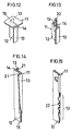
- the rib 13 has a uniform width from top to bottom of each leg, it may have a gradually decreasing width (Fig. 9) toward its bottom end so that the rib can be bent more easily from the leg body and the legs will spread more easily when the nail is driven.
- the rib 13 may have a plurality of saw tooth shaped projections 17 on its edge (Fig. 10) to facilitate the spreading of the legs and to increase the resistance to a pulling force applied to the nail.
- the nail 11 may be provided at its top with a hole 18 (Fig. 11) for a wire and so on, or with a cap 19 (Fig. 12) for stable driving of the nail and for the prevention of its damage, or with a threaded shaft 20 having a male screw (Fig.13).
- the rib 13 may not extend as far as to the top end of the leg 12 but short of it as shown in Fig. 11. It may also be formed with an outward bend at its top end to prevent the nail from being driven too deep.
- Fig. 14 shows another embodiment in which the rib 13 of each leg has a gradually decreasing width and does not extend as fas as to the lower end of the leg but short of it.
- the bottom ends of the legs 12 serve as a guide when the nail is driven.
- each leg 12 is formed with a further rib 21 at the side opposite to the side at which the rib 13 is formed, said further rib extending in a direction opposite to the direction in which the rib 13 extends.
- Fig. 15 shows a further embodiment in which each leg has a rib formed with a plurality of projections 22 and the legs are caulked together at one edge thereof instead of being welded or bolted to put them together.
- the nail in accordance with the present invention is used to fasten e.g. metal fittings or an outer trim or covering to a member A of such a material as foamed concrete or a heat insulating material.
- the nail 11 is driven in an ordinary manner by striking its head 14.
- its legs advance into the member A and their tips gradually spread apart from each other because of the resistance acted thereon by the member.
- the legs 12 will get apart from each other at their tip as shown in Fig. 4.
- the legs advance into the member A, its material caught between the legs is compressed. Since the legs have a rib extending toward each other leg, they form a tubular space of a rectangular section between them as they spread apart, as best shown in Fig. 6. The material in this space is compressed and trapped with no place of escape. The trapped and compressed material serves to prevent the legs from getting out of the member A when a pulling force is applied to the nail. This, coupled with the spreading of the legs, provides a sufficient resistance to any pulling force. Even if the nail were pulled for some or other reason, the nail would not get off easily.
- the provision of the ribs 13 gives the nail the maximum width H (Fig. 5), thus substantially increasing its load bearing capacity and preventing the member from getting damaged by the nail itself under load.
- the nail according to the present invention will not come off or loosen easily even if it is used for members of such a material as foamed concrete.
Landscapes
- Engineering & Computer Science (AREA)
- General Engineering & Computer Science (AREA)
- Mechanical Engineering (AREA)
- Joining Of Building Structures In Genera (AREA)
- Building Environments (AREA)
- Acyclic And Carbocyclic Compounds In Medicinal Compositions (AREA)
Applications Claiming Priority (2)
| Application Number | Priority Date | Filing Date | Title |
|---|---|---|---|
| JP46736/81 | 1981-03-31 | ||
| JP1981046736U JPS585122Y2 (ja) | 1981-03-31 | 1981-03-31 | 釘 |
Publications (2)
| Publication Number | Publication Date |
|---|---|
| EP0061742A1 true EP0061742A1 (de) | 1982-10-06 |
| EP0061742B1 EP0061742B1 (de) | 1985-12-11 |
Family
ID=12755607
Family Applications (1)
| Application Number | Title | Priority Date | Filing Date |
|---|---|---|---|
| EP82102566A Expired EP0061742B1 (de) | 1981-03-31 | 1982-03-26 | Nagel |
Country Status (4)
| Country | Link |
|---|---|
| EP (1) | EP0061742B1 (de) |
| JP (1) | JPS585122Y2 (de) |
| AT (1) | ATE16956T1 (de) |
| DE (1) | DE3267867D1 (de) |
Families Citing this family (4)
| Publication number | Priority date | Publication date | Assignee | Title |
|---|---|---|---|---|
| DE19734518A1 (de) * | 1997-08-08 | 1999-02-11 | Fischer Artur Werke Gmbh | Spreiznagel |
| JPH11201122A (ja) * | 1998-01-14 | 1999-07-27 | Wakai & Co Ltd | Alc用のアンカー釘 |
| DE10061021A1 (de) * | 2000-03-21 | 2001-09-27 | Lutz Von Der Planitz | Zusammenwirken mehrerer gemeinsam eingeschlagener Nägel |
| DE10134728C2 (de) * | 2001-07-17 | 2003-12-04 | Von Der Planitz Lutz Edler | Gleichgeformte, gemeinsam in ein Werkstück eintreibbare Nägel-mit im Querschnitt jeweils rundem Nagelschaft |
Citations (6)
| Publication number | Priority date | Publication date | Assignee | Title |
|---|---|---|---|---|
| US2603121A (en) * | 1945-12-12 | 1952-07-15 | Elastic Stop Nut Corp | Self-locking nail |
| US2751052A (en) * | 1953-09-02 | 1956-06-19 | Tinnerman Products Inc | Joint for roofing, wall, floor or the like |
| US3466967A (en) * | 1968-03-12 | 1969-09-16 | Robert L Hallock | Tapered sheet metal nail |
| US3812817A (en) * | 1973-01-29 | 1974-05-28 | R Hallock | Sheet metal nail and apparatus for testing |
| US3874263A (en) * | 1972-02-29 | 1975-04-01 | Illinois Tool Works | Metal penetrating staple |
| US4213373A (en) * | 1978-12-12 | 1980-07-22 | Hallock Robert L | Sheet metal nail with lockable legs |
-
1981
- 1981-03-31 JP JP1981046736U patent/JPS585122Y2/ja not_active Expired
-
1982
- 1982-03-26 AT AT82102566T patent/ATE16956T1/de not_active IP Right Cessation
- 1982-03-26 EP EP82102566A patent/EP0061742B1/de not_active Expired
- 1982-03-26 DE DE8282102566T patent/DE3267867D1/de not_active Expired
Patent Citations (6)
| Publication number | Priority date | Publication date | Assignee | Title |
|---|---|---|---|---|
| US2603121A (en) * | 1945-12-12 | 1952-07-15 | Elastic Stop Nut Corp | Self-locking nail |
| US2751052A (en) * | 1953-09-02 | 1956-06-19 | Tinnerman Products Inc | Joint for roofing, wall, floor or the like |
| US3466967A (en) * | 1968-03-12 | 1969-09-16 | Robert L Hallock | Tapered sheet metal nail |
| US3874263A (en) * | 1972-02-29 | 1975-04-01 | Illinois Tool Works | Metal penetrating staple |
| US3812817A (en) * | 1973-01-29 | 1974-05-28 | R Hallock | Sheet metal nail and apparatus for testing |
| US4213373A (en) * | 1978-12-12 | 1980-07-22 | Hallock Robert L | Sheet metal nail with lockable legs |
Also Published As
| Publication number | Publication date |
|---|---|
| EP0061742B1 (de) | 1985-12-11 |
| JPS585122Y2 (ja) | 1983-01-28 |
| DE3267867D1 (en) | 1986-01-23 |
| JPS57159012U (de) | 1982-10-06 |
| ATE16956T1 (de) | 1985-12-15 |
Similar Documents
| Publication | Publication Date | Title |
|---|---|---|
| US4625489A (en) | Wedge for use in lattice substructures of wall panels | |
| US4924646A (en) | Wire guard | |
| US4641474A (en) | Sta-put wallboard joiner | |
| EP0576034B1 (de) | Befestigungsnagel | |
| KR102331558B1 (ko) | 금속 프로파일과 브라켓의 고정장치 | |
| US3438664A (en) | Structural assembly and clip | |
| US3499359A (en) | Easy pull staple | |
| KR102320288B1 (ko) | 조립식 앵글 | |
| EP0061742A1 (de) | Nagel | |
| KR20120093868A (ko) | 파이버의 종방향으로 연장되는 파이버변부에서 모따기 구조를 가진 금속 파이버 | |
| US4208148A (en) | Wedge for wooden handled tool | |
| US6679669B2 (en) | Fastener for wood having locking portion | |
| US5605422A (en) | Nail with expansion region | |
| US4141575A (en) | Coupling sleeve | |
| US2371935A (en) | Joint nail or clip | |
| EP1083340B1 (de) | Federelement | |
| EP0263819B1 (de) | Vorrichtung zum verankern in und/oder verstärken von harten materialien | |
| JP7622983B2 (ja) | シート定着フレーム | |
| JP2003161308A (ja) | 打ち込みアンカー | |
| US5957643A (en) | Fastening element with expansible member | |
| JP2004190459A (ja) | 螺軸固定構造及び土留め壁用コンクリート型枠連結具 | |
| EP0064556B1 (de) | Nagel | |
| JPS609452Y2 (ja) | 釘 | |
| JPH08320008A (ja) | 拡張部材を有する固定部材 | |
| JPS6111534Y2 (de) |
Legal Events
| Date | Code | Title | Description |
|---|---|---|---|
| PUAI | Public reference made under article 153(3) epc to a published international application that has entered the european phase |
Free format text: ORIGINAL CODE: 0009012 |
|
| AK | Designated contracting states |
Designated state(s): AT DE FR NL SE |
|
| 17P | Request for examination filed |
Effective date: 19830406 |
|
| GRAA | (expected) grant |
Free format text: ORIGINAL CODE: 0009210 |
|
| AK | Designated contracting states |
Designated state(s): AT DE FR NL SE |
|
| REF | Corresponds to: |
Ref document number: 16956 Country of ref document: AT Date of ref document: 19851215 Kind code of ref document: T |
|
| REF | Corresponds to: |
Ref document number: 3267867 Country of ref document: DE Date of ref document: 19860123 |
|
| ET | Fr: translation filed | ||
| PLBE | No opposition filed within time limit |
Free format text: ORIGINAL CODE: 0009261 |
|
| STAA | Information on the status of an ep patent application or granted ep patent |
Free format text: STATUS: NO OPPOSITION FILED WITHIN TIME LIMIT |
|
| 26N | No opposition filed | ||
| PGFP | Annual fee paid to national office [announced via postgrant information from national office to epo] |
Ref country code: FR Payment date: 19940117 Year of fee payment: 13 |
|
| PGFP | Annual fee paid to national office [announced via postgrant information from national office to epo] |
Ref country code: SE Payment date: 19940329 Year of fee payment: 13 Ref country code: AT Payment date: 19940329 Year of fee payment: 13 |
|
| PGFP | Annual fee paid to national office [announced via postgrant information from national office to epo] |
Ref country code: NL Payment date: 19940331 Year of fee payment: 13 |
|
| PGFP | Annual fee paid to national office [announced via postgrant information from national office to epo] |
Ref country code: DE Payment date: 19940524 Year of fee payment: 13 |
|
| EAL | Se: european patent in force in sweden |
Ref document number: 82102566.5 |
|
| PG25 | Lapsed in a contracting state [announced via postgrant information from national office to epo] |
Ref country code: AT Effective date: 19950326 |
|
| PG25 | Lapsed in a contracting state [announced via postgrant information from national office to epo] |
Ref country code: SE Effective date: 19950327 |
|
| PG25 | Lapsed in a contracting state [announced via postgrant information from national office to epo] |
Ref country code: NL Effective date: 19951001 |
|
| PG25 | Lapsed in a contracting state [announced via postgrant information from national office to epo] |
Ref country code: FR Free format text: LAPSE BECAUSE OF NON-PAYMENT OF DUE FEES Effective date: 19951130 |
|
| NLV4 | Nl: lapsed or anulled due to non-payment of the annual fee |
Effective date: 19951001 |
|
| PG25 | Lapsed in a contracting state [announced via postgrant information from national office to epo] |
Ref country code: DE Effective date: 19951201 |
|
| EUG | Se: european patent has lapsed |
Ref document number: 82102566.5 |
|
| REG | Reference to a national code |
Ref country code: FR Ref legal event code: ST |