EP0061755B1 - Appareil à dessiner relié à un ordinateur - Google Patents
Appareil à dessiner relié à un ordinateur Download PDFInfo
- Publication number
- EP0061755B1 EP0061755B1 EP82102608A EP82102608A EP0061755B1 EP 0061755 B1 EP0061755 B1 EP 0061755B1 EP 82102608 A EP82102608 A EP 82102608A EP 82102608 A EP82102608 A EP 82102608A EP 0061755 B1 EP0061755 B1 EP 0061755B1
- Authority
- EP
- European Patent Office
- Prior art keywords
- plotter
- drawing machine
- machine according
- carriage
- guide
- Prior art date
- Legal status (The legal status is an assumption and is not a legal conclusion. Google has not performed a legal analysis and makes no representation as to the accuracy of the status listed.)
- Expired
Links
Images

Classifications
-
- B—PERFORMING OPERATIONS; TRANSPORTING
- B43—WRITING OR DRAWING IMPLEMENTS; BUREAU ACCESSORIES
- B43L—ARTICLES FOR WRITING OR DRAWING UPON; WRITING OR DRAWING AIDS; ACCESSORIES FOR WRITING OR DRAWING
- B43L13/00—Drawing instruments, or writing or drawing appliances or accessories not otherwise provided for
- B43L13/02—Draughting machines or drawing devices for keeping parallelism
- B43L13/022—Draughting machines or drawing devices for keeping parallelism automatic
-
- G—PHYSICS
- G05—CONTROLLING; REGULATING
- G05B—CONTROL OR REGULATING SYSTEMS IN GENERAL; FUNCTIONAL ELEMENTS OF SUCH SYSTEMS; MONITORING OR TESTING ARRANGEMENTS FOR SUCH SYSTEMS OR ELEMENTS
- G05B19/00—Program-control systems
- G05B19/02—Program-control systems electric
- G05B19/42—Recording and playback systems, i.e. in which the program is recorded from a cycle of operations, e.g. the cycle of operations being manually controlled, after which this record is played back on the same machine
- G05B19/4202—Recording and playback systems, i.e. in which the program is recorded from a cycle of operations, e.g. the cycle of operations being manually controlled, after which this record is played back on the same machine preparation of the program medium using a drawing, a model
- G05B19/4205—Recording and playback systems, i.e. in which the program is recorded from a cycle of operations, e.g. the cycle of operations being manually controlled, after which this record is played back on the same machine preparation of the program medium using a drawing, a model in which a drawing is traced or scanned and corresponding data recorded
-
- G—PHYSICS
- G06—COMPUTING OR CALCULATING; COUNTING
- G06K—GRAPHICAL DATA READING; PRESENTATION OF DATA; RECORD CARRIERS; HANDLING RECORD CARRIERS
- G06K15/00—Arrangements for producing a permanent visual presentation of the output data, e.g. computer output printers
- G06K15/22—Arrangements for producing a permanent visual presentation of the output data, e.g. computer output printers using plotters
-
- G—PHYSICS
- G05—CONTROLLING; REGULATING
- G05B—CONTROL OR REGULATING SYSTEMS IN GENERAL; FUNCTIONAL ELEMENTS OF SUCH SYSTEMS; MONITORING OR TESTING ARRANGEMENTS FOR SUCH SYSTEMS OR ELEMENTS
- G05B2219/00—Program-control systems
- G05B2219/30—Nc systems
- G05B2219/36—Nc in input of data, input key till input tape
- G05B2219/36429—Power assisted positioning
-
- G—PHYSICS
- G05—CONTROLLING; REGULATING
- G05B—CONTROL OR REGULATING SYSTEMS IN GENERAL; FUNCTIONAL ELEMENTS OF SUCH SYSTEMS; MONITORING OR TESTING ARRANGEMENTS FOR SUCH SYSTEMS OR ELEMENTS
- G05B2219/00—Program-control systems
- G05B2219/30—Nc systems
- G05B2219/45—Nc applications
- G05B2219/45189—Plotter
Definitions
- the invention relates to a carriage drawing machine with a drawing area arranged on a drawing board and with a drawing head which can be moved over the drawing area by means of carriages.
- a disadvantage of such plotters is that they only have a relatively limited drawing area up to approximately A3 and that their positioning in a defined position in relation to the prepared drawing, which is required several times when processing a larger drawing format, is therefore relatively time-consuming and difficult and involves a considerable risk of Brings mistakes. It is also disadvantageous that either the plotter has to be transported to the drawing station, in particular to a drawing machine, when the preparatory work has been completed, or that the prepared drawing has to be transported to the workstation for the plotter and fixed there again.
- the object of the invention is to provide such a drawing machine with a plotter in such a way that time-consuming positioning of the plotter and drawing relative to one another is eliminated.
- the carriage drawing machine according to the invention has the advantage that the transport of the plotter to the drawing machine or that of the drawing to the plotter's workplace are eliminated.
- the plotter is mounted on the carriage drawing machine according to the invention. As long as this is used to make a drawing, the plotter can be pushed into a position that does not hinder the drawing work, it is then immediately ready for labeling or other additional work, without requiring a greater amount of time to position it.
- the particular advantage of the combination of drawing machine and plotter according to the invention is that a drawing drawn on the carriage drawing machine can remain on the drawing board and can then be supplemented by the plotter, initially because of the same drawing board on which the guide rails for the drawing head arrangement of the Drawing machine on the one hand and the plotter on the other hand, the ganue XY positioning of the drawing sheet is guaranteed.
- it is no problem to work alternately with the drawing machine and with the plotter for example if, after drawing in a partial construction with the aid of the plotter, the drawing work is to be continued with the drawing machine.
- Possibilities are characterized in the subclaims as to how the union of a carriage drawing machine with a plotter can be designed particularly advantageously. There are very special advantages if the drawing machine is computer-controlled, with which it is possible to store the various data about the plotter's attachment points and the symbols, partial figures, etc. to be drawn at these attachment points when drawing with the drawing machine in the memory of the Computer.
- EP-A-0148160 is a method for making drawings and a drawing machine for carrying out this method, a plotter not being a necessary element of the invention, but only is provided in an advantageous development of the invention.
- FIG. 1 shows a work station with a carriage drawing machine and a plotter arrangement, on which a modified carriage drawing machine 10 with an associated computer 12, for example a microcomputer with disk drives, and a plotter 32 are provided.
- a keyboard 14 which can be moved in the horizontal direction, that is to say in the X direction, is provided on the drawing machine 10 and is connected to the drawing machine 10 and the computer 12 via corresponding lines (not shown).
- a work table 16 is provided at right angles to the drawing machine 10, on which there are additional devices connected to the computer 12, namely a pivotable data monitor 18, a printer / typewriter arrangement 20 and a graphic tablet 21.
- the plotter 32 is provided on the drawing machine 10 on the right edge of the drawing board and is provided with a pen magazine 40.
- the plotter 32 is connected to an additional carriage of the drawing machine 10, the support arm 34 of which can be moved in the X direction of the drawing board 30.
- the drawing machine 10 comprises a carriage device 22 which can be moved in the X direction and is shown in its leftmost position and which is provided with a drawing head carrier 24 which has a writing / reading pen carrier 26 which, in principle, acts as a simple holder for a writing or Drawing pen and a reading pen can be formed.
- the write / read pen carrier is designed as a turret head with several — three in FIG. 1 — pens 27; for the sake of simplicity, it is therefore referred to below as a pen turret 26.
- the housing 28 which is part of the X-Y guide and contains the required servo electronics with at least one positioning motor and devices for path measurement.
- the pen turret 26 is connected to the drawing head carrier 24, then there is the possibility, unlike in the case of the drawing devices based on carriage drawing machines that have been customary up to now, by moving the pen turret 26 to draw directly against the drawing board 30 with the drawing pen 27 located in the drawing position. Further, now via the existing between the drawing engine 10 and the computer 12 - n line connections immediate storage of the coordinate data for the carried out with the pen 27 drawn line. In this way, first of all the data are collected which later, when the drawing pen 27 is automatically controlled by the computer 12, allow an exact reconstruction of an earlier drawing, whereby any necessary additions and corrections can be taken into account.
- the electronic weight compensation works in such a way that the movements of the pen revolver initiated by the draftsman are supported by the servo electronics, so that the pen revolver can be moved as freely as the drawing head 26 'a normal drawing machine.
- the data for the relevant line for example in the form of the coordinates of the end points of a straight line or in the form of the data about the center point and radius of a circle to be drawn, are previously keyed in on the keyboard 14, with the possibility of using the inputs to call up assigned subroutines on the keyboard 14 from the computer 12.
- the servo electronics devices are then controlled in such a way that, for the movement of the turret 26, there is practically an electronic link guide which forces the drawing of a specific, fixed line.
- the draftsman During the movement of the turret 26 along the line defined by the electronic backdrop guide, the draftsman then has the opportunity to enter additional data into the computer 12 via the keyboard 14 when certain points of the line are reached, such as auxiliary points for the dimensioning, points for the attachment of Reference symbols, points for supplementing the drawing with predetermined partial figures, points for the attachment of processing symbols, etc. can relate.
- a particular advantage of the drawing device is that it can also work in "copy mode".
- a prepared drawing is stretched onto the drawing board 30, the individual lines of which are then scanned with a reading pen carried by the pen revolver, this "reading pen", which can be, for example, a simple, non-writing steel pen with a rounded tip, on the drawing lines of interest is guided along in order to transfer their coordinate data into the memory part of the computer 12, whereby tremors or inaccuracies in line scanning with a free, manually operated turret 26 can be corrected by corresponding electronic correction circuits of the computer, but also taking into account the possibility is the pen to equip the revolver with the scanning devices known, for example, in fabric cutting machines, so that the drawing can be scanned more or less fully automatically.
- the path guidance for the turret 26 also allows complicated shapes, depending on the computer program, it can be used manually along the released lines, for example for drawing circular paths, symbols, characters and mathematical functions. This eliminates the need to use compasses, templates, curve rulers, etc. Furthermore, curves can be approximated by moving to the most important points using the computer and then drawn. Finally, the drawing device according to the invention can also be used for drawing dashed or dash-dotted lines, the write / read pen carrier being equipped for this purpose with a controllable pen attachment mechanism which can be controlled via the computer, which can also be achieved, for example, that when drawing broken lines do not exactly drop gaps on the intersection points with other lines.
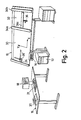
- the plotter arrangement shown in FIG. 2 differs from the plotter arrangement explained above with reference to FIG. 1 essentially in that the carriage drawing machine 10 is designed with the usual drawing head 26 'and the rulers attached to it. However, the drawing board is considerably extended in the X direction in order to make room for the hanging of the plotter 32, the support means of which in this exemplary embodiment is designed as a frame 34a, 34b with two guide arms which run in the Y direction and between which one in X. -Directional guide arm 34c is guided with the pen 36.
- a keyboard 14 which can be moved along the drawing machine 10 and which is again connected to an assigned computer 12 is provided, similarly to the embodiment according to FIG. 1.
- the computer 12 and the keyboard 14 serve to control the plotter 32. During normal drawing, this can be completely moved out of the working area of the drawing devices due to the excess length of the drawing board 30.
- it can be used to detect the entire drawing surface, if necessary, after removing the drawing head 26 'and the rulers from the drawing head carrier 24 by moving along the guide rail on the drawing board.
- clearly noticeable locking positions can be provided which facilitate the positioning of the plotter in defined positions with respect to the origin for the drawing work to be carried out with the drawing machine 10.
Landscapes
- Engineering & Computer Science (AREA)
- Physics & Mathematics (AREA)
- General Physics & Mathematics (AREA)
- Automation & Control Theory (AREA)
- General Engineering & Computer Science (AREA)
- Theoretical Computer Science (AREA)
- Powder Metallurgy (AREA)
- Measurement And Recording Of Electrical Phenomena And Electrical Characteristics Of The Living Body (AREA)
- Processing Or Creating Images (AREA)
- Image Generation (AREA)
Claims (14)
Priority Applications (1)
| Application Number | Priority Date | Filing Date | Title |
|---|---|---|---|
| AT82102608T ATE23489T1 (de) | 1981-03-30 | 1982-03-27 | Rechnergesteuerte plotteranordnung. |
Applications Claiming Priority (2)
| Application Number | Priority Date | Filing Date | Title |
|---|---|---|---|
| DE3112551 | 1981-03-30 | ||
| DE19813112551 DE3112551A1 (de) | 1981-03-30 | 1981-03-30 | Rechnergesteuerte plotteranordnung |
Related Child Applications (2)
| Application Number | Title | Priority Date | Filing Date |
|---|---|---|---|
| EP85100673.4 Division-Into | 1982-03-27 | ||
| EP85100673A Division EP0148160A3 (fr) | 1981-03-30 | 1982-03-27 | Procédé et machine pour tracer des dessins |
Publications (2)
| Publication Number | Publication Date |
|---|---|
| EP0061755A1 EP0061755A1 (fr) | 1982-10-06 |
| EP0061755B1 true EP0061755B1 (fr) | 1986-11-12 |
Family
ID=6128715
Family Applications (2)
| Application Number | Title | Priority Date | Filing Date |
|---|---|---|---|
| EP82102608A Expired EP0061755B1 (fr) | 1981-03-30 | 1982-03-27 | Appareil à dessiner relié à un ordinateur |
| EP85100673A Withdrawn EP0148160A3 (fr) | 1981-03-30 | 1982-03-27 | Procédé et machine pour tracer des dessins |
Family Applications After (1)
| Application Number | Title | Priority Date | Filing Date |
|---|---|---|---|
| EP85100673A Withdrawn EP0148160A3 (fr) | 1981-03-30 | 1982-03-27 | Procédé et machine pour tracer des dessins |
Country Status (3)
| Country | Link |
|---|---|
| EP (2) | EP0061755B1 (fr) |
| AT (1) | ATE23489T1 (fr) |
| DE (2) | DE3112551A1 (fr) |
Families Citing this family (3)
| Publication number | Priority date | Publication date | Assignee | Title |
|---|---|---|---|---|
| US4785546A (en) * | 1987-06-03 | 1988-11-22 | Achilles Tomasini | Lithographic production planning system |
| DE4228416A1 (de) * | 1992-08-31 | 1994-03-03 | Helmut Obieglo | Vorrichtung für eine Zeichenmaschine |
| CN109920029A (zh) * | 2019-03-18 | 2019-06-21 | 河北华发教育科技股份有限公司 | 一种绘制可擦除图形的方法 |
Family Cites Families (6)
| Publication number | Priority date | Publication date | Assignee | Title |
|---|---|---|---|---|
| GB1030331A (en) * | 1963-01-09 | 1966-05-18 | D Mac Ltd | Graph plotting mechanism |
| NL6705263A (fr) * | 1967-04-14 | 1968-10-15 | ||
| US3693066A (en) * | 1970-08-24 | 1972-09-19 | Computervision Corp | Natural feeling common drive plotter-digitizer |
| US3714714A (en) * | 1971-02-12 | 1973-02-06 | E Bullard | Drafting machine |
| US3936712A (en) * | 1973-04-20 | 1976-02-03 | The Gerber Scientific Instrument Company | Interactive graphic system |
| DE2450576C2 (de) * | 1974-10-24 | 1984-03-01 | Marabuwerke Erwin Martz Gmbh & Co, 7146 Tamm | Laufwagen-Zeichenmaschine |
-
1981
- 1981-03-30 DE DE19813112551 patent/DE3112551A1/de not_active Withdrawn
-
1982
- 1982-03-27 DE DE8282102608T patent/DE3274222D1/de not_active Expired
- 1982-03-27 EP EP82102608A patent/EP0061755B1/fr not_active Expired
- 1982-03-27 EP EP85100673A patent/EP0148160A3/fr not_active Withdrawn
- 1982-03-27 AT AT82102608T patent/ATE23489T1/de not_active IP Right Cessation
Also Published As
| Publication number | Publication date |
|---|---|
| EP0148160A2 (fr) | 1985-07-10 |
| DE3274222D1 (en) | 1987-01-02 |
| DE3112551A1 (de) | 1982-10-28 |
| ATE23489T1 (de) | 1986-11-15 |
| EP0148160A3 (fr) | 1987-11-25 |
| EP0061755A1 (fr) | 1982-10-06 |
Similar Documents
| Publication | Publication Date | Title |
|---|---|---|
| DE2913690C2 (de) | Schreibstiftwechseleinrichtung | |
| EP0126915A2 (fr) | Dispostiion d'entrée d'informations | |
| DE3211174C2 (de) | Rechnergestützte Zeichenmaschine | |
| DE102018200551A1 (de) | Bearbeitungsvorrichtung | |
| DE1588089B2 (fr) | ||
| DE2809480C3 (de) | Zeichengerät | |
| DE2925613C2 (de) | Vorrichtung zum Steuern einer an einen Computer angeschlossenen Zeichenmaschine mittels einer Digitalisiereinrichtung | |
| DE3129470A1 (de) | Verfahren und vorrichtung zum aufnehmen und wiedergeben beliebiger darstellungen mit einer schreib- oder zeichenmaschine | |
| EP0061755A1 (fr) | Appareil à dessiner relié à un ordinateur | |
| DE3220568A1 (de) | Numerisch gesteuertes schreibgeraet | |
| DE3110271C2 (de) | Zeicheneinrichtung | |
| EP0061754A1 (fr) | Appareil à dessiner relié à un ordinateur | |
| DE2213169B2 (de) | Photogrammetrisches Auswertegerät | |
| DE3606099A1 (de) | Zeichnungshilfe zum anfertigen von perspektivischen zeichnungen | |
| DE2134793C2 (de) | An einem Zeichentisch anbringbare Zeichenvorrichtung | |
| DE8109369U1 (de) | Rechnergesteuertes zeichengeraet | |
| DE8109368U1 (de) | Zeichengeraet mit einer laufwagen-zeichenmaschine | |
| DE1752336A1 (de) | Werkzeugmaschinensimulator | |
| DE2901601A1 (de) | Zeichenvorrichtung zur erstellung technischer zeichnungen | |
| DE4307757A1 (de) | Vorrichtung zur Bearbeitung von Holzwerkstücken mit einer Kennzeichnungs-Station | |
| DE112020007797B4 (de) | Werkzeugmaschine | |
| DE1461574C (de) | Gerät zum Abbilden eines Gegenstandes in Zentralperspektive | |
| DE3128699A1 (de) | Miniplotter | |
| DE1538660A1 (de) | Verfahren und Anordnung zur selbsttaetigen Umwandlung von Positionen einer Zeichenflaeche in numerische Form | |
| DE2219076C3 (de) | Verfahren und Vorrichtung zum GröBenverändern von Schnittmustern |
Legal Events
| Date | Code | Title | Description |
|---|---|---|---|
| PUAI | Public reference made under article 153(3) epc to a published international application that has entered the european phase |
Free format text: ORIGINAL CODE: 0009012 |
|
| AK | Designated contracting states |
Designated state(s): AT BE CH DE FR GB IT LU NL SE |
|
| 17P | Request for examination filed |
Effective date: 19830406 |
|
| GRAA | (expected) grant |
Free format text: ORIGINAL CODE: 0009210 |
|
| AK | Designated contracting states |
Kind code of ref document: B1 Designated state(s): AT BE CH DE FR GB IT LI LU NL SE |
|
| REF | Corresponds to: |
Ref document number: 23489 Country of ref document: AT Date of ref document: 19861115 Kind code of ref document: T |
|
| ITF | It: translation for a ep patent filed | ||
| REF | Corresponds to: |
Ref document number: 3274222 Country of ref document: DE Date of ref document: 19870102 |
|
| PGFP | Annual fee paid to national office [announced via postgrant information from national office to epo] |
Ref country code: AT Payment date: 19870327 Year of fee payment: 6 |
|
| PG25 | Lapsed in a contracting state [announced via postgrant information from national office to epo] |
Ref country code: LU Free format text: LAPSE BECAUSE OF NON-PAYMENT OF DUE FEES Effective date: 19870331 |
|
| PGFP | Annual fee paid to national office [announced via postgrant information from national office to epo] |
Ref country code: NL Payment date: 19870331 Year of fee payment: 6 |
|
| PLBE | No opposition filed within time limit |
Free format text: ORIGINAL CODE: 0009261 |
|
| STAA | Information on the status of an ep patent application or granted ep patent |
Free format text: STATUS: NO OPPOSITION FILED WITHIN TIME LIMIT |
|
| 26N | No opposition filed | ||
| PG25 | Lapsed in a contracting state [announced via postgrant information from national office to epo] |
Ref country code: AT Effective date: 19880327 |
|
| PG25 | Lapsed in a contracting state [announced via postgrant information from national office to epo] |
Ref country code: SE Effective date: 19880328 |
|
| PG25 | Lapsed in a contracting state [announced via postgrant information from national office to epo] |
Ref country code: LI Effective date: 19880331 Ref country code: CH Effective date: 19880331 |
|
| BERE | Be: lapsed |
Owner name: BZ PLANKENHORN K.G. Effective date: 19880331 |
|
| PG25 | Lapsed in a contracting state [announced via postgrant information from national office to epo] |
Ref country code: NL Effective date: 19881001 |
|
| NLV4 | Nl: lapsed or anulled due to non-payment of the annual fee | ||
| PG25 | Lapsed in a contracting state [announced via postgrant information from national office to epo] |
Ref country code: GB Free format text: LAPSE BECAUSE OF NON-PAYMENT OF DUE FEES Effective date: 19881121 |
|
| GBPC | Gb: european patent ceased through non-payment of renewal fee | ||
| PG25 | Lapsed in a contracting state [announced via postgrant information from national office to epo] |
Ref country code: FR Free format text: LAPSE BECAUSE OF NON-PAYMENT OF DUE FEES Effective date: 19881130 |
|
| REG | Reference to a national code |
Ref country code: CH Ref legal event code: PL |
|
| PG25 | Lapsed in a contracting state [announced via postgrant information from national office to epo] |
Ref country code: DE Effective date: 19881201 |
|
| REG | Reference to a national code |
Ref country code: FR Ref legal event code: ST |
|
| PG25 | Lapsed in a contracting state [announced via postgrant information from national office to epo] |
Ref country code: BE Effective date: 19890331 |
|
| EUG | Se: european patent has lapsed |
Ref document number: 82102608.5 Effective date: 19881206 |