EP0061788B1 - Procédé et appareil pour raccorder des bandes de matériau d'emballage - Google Patents
Procédé et appareil pour raccorder des bandes de matériau d'emballage Download PDFInfo
- Publication number
- EP0061788B1 EP0061788B1 EP82200248A EP82200248A EP0061788B1 EP 0061788 B1 EP0061788 B1 EP 0061788B1 EP 82200248 A EP82200248 A EP 82200248A EP 82200248 A EP82200248 A EP 82200248A EP 0061788 B1 EP0061788 B1 EP 0061788B1
- Authority
- EP
- European Patent Office
- Prior art keywords
- signal
- web
- mark
- time
- controlling device
- Prior art date
- Legal status (The legal status is an assumption and is not a legal conclusion. Google has not performed a legal analysis and makes no representation as to the accuracy of the status listed.)
- Expired
Links
- 239000000463 material Substances 0.000 title claims description 70
- 238000012856 packing Methods 0.000 title claims description 54
- 238000000034 method Methods 0.000 title claims description 15
- 238000007789 sealing Methods 0.000 claims description 34
- 238000007664 blowing Methods 0.000 claims description 13
- 230000001143 conditioned effect Effects 0.000 claims description 12
- 230000001939 inductive effect Effects 0.000 claims description 11
- 239000000853 adhesive Substances 0.000 claims description 7
- 230000001070 adhesive effect Effects 0.000 claims description 7
- 230000000977 initiatory effect Effects 0.000 claims description 3
- 230000003750 conditioning effect Effects 0.000 claims description 2
- 238000012937 correction Methods 0.000 description 4
- 230000001419 dependent effect Effects 0.000 description 2
- 239000002390 adhesive tape Substances 0.000 description 1
- 238000004891 communication Methods 0.000 description 1
- 238000013461 design Methods 0.000 description 1
- 238000001514 detection method Methods 0.000 description 1
- 230000005284 excitation Effects 0.000 description 1
- 230000001012 protector Effects 0.000 description 1
Images


Classifications
-
- B—PERFORMING OPERATIONS; TRANSPORTING
- B65—CONVEYING; PACKING; STORING; HANDLING THIN OR FILAMENTARY MATERIAL
- B65H—HANDLING THIN OR FILAMENTARY MATERIAL, e.g. SHEETS, WEBS, CABLES
- B65H19/00—Changing the web roll
- B65H19/10—Changing the web roll in unwinding mechanisms or in connection with unwinding operations
- B65H19/18—Attaching, e.g. pasting, the replacement web to the expiring web
- B65H19/1857—Support arrangement of web rolls
- B65H19/1873—Support arrangement of web rolls with two stationary roll supports carrying alternately the replacement and the expiring roll
-
- B—PERFORMING OPERATIONS; TRANSPORTING
- B65—CONVEYING; PACKING; STORING; HANDLING THIN OR FILAMENTARY MATERIAL
- B65B—MACHINES, APPARATUS OR DEVICES FOR, OR METHODS OF, PACKAGING ARTICLES OR MATERIALS; UNPACKING
- B65B41/00—Supplying or feeding container-forming sheets or wrapping material
- B65B41/18—Registering sheets, blanks, or webs
-
- B—PERFORMING OPERATIONS; TRANSPORTING
- B65—CONVEYING; PACKING; STORING; HANDLING THIN OR FILAMENTARY MATERIAL
- B65B—MACHINES, APPARATUS OR DEVICES FOR, OR METHODS OF, PACKAGING ARTICLES OR MATERIALS; UNPACKING
- B65B57/00—Automatic control, checking, warning, or safety devices
- B65B57/02—Automatic control, checking, warning, or safety devices responsive to absence, presence, abnormal feed, or misplacement of binding or wrapping material, containers, or packages
-
- B—PERFORMING OPERATIONS; TRANSPORTING
- B65—CONVEYING; PACKING; STORING; HANDLING THIN OR FILAMENTARY MATERIAL
- B65H—HANDLING THIN OR FILAMENTARY MATERIAL, e.g. SHEETS, WEBS, CABLES
- B65H19/00—Changing the web roll
- B65H19/10—Changing the web roll in unwinding mechanisms or in connection with unwinding operations
- B65H19/18—Attaching, e.g. pasting, the replacement web to the expiring web
- B65H19/1805—Flying splicing, i.e. the expiring web moving during splicing contact
- B65H19/1826—Flying splicing, i.e. the expiring web moving during splicing contact taking place at a distance from the replacement roll
- B65H19/1831—Flying splicing, i.e. the expiring web moving during splicing contact taking place at a distance from the replacement roll the replacement web being stationary prior to splicing contact
-
- B—PERFORMING OPERATIONS; TRANSPORTING
- B65—CONVEYING; PACKING; STORING; HANDLING THIN OR FILAMENTARY MATERIAL
- B65H—HANDLING THIN OR FILAMENTARY MATERIAL, e.g. SHEETS, WEBS, CABLES
- B65H21/00—Apparatus for splicing webs
- B65H21/02—Apparatus for splicing webs for premarked, e.g. preprinted, webs
-
- B—PERFORMING OPERATIONS; TRANSPORTING
- B65—CONVEYING; PACKING; STORING; HANDLING THIN OR FILAMENTARY MATERIAL
- B65H—HANDLING THIN OR FILAMENTARY MATERIAL, e.g. SHEETS, WEBS, CABLES
- B65H2301/00—Handling processes for sheets or webs
- B65H2301/40—Type of handling process
- B65H2301/46—Splicing
- B65H2301/4601—Splicing special splicing features or applications
- B65H2301/46018—Splicing special splicing features or applications involving location or further processing of splice
- B65H2301/460183—Splicing special splicing features or applications involving location or further processing of splice marking of splice
-
- B—PERFORMING OPERATIONS; TRANSPORTING
- B65—CONVEYING; PACKING; STORING; HANDLING THIN OR FILAMENTARY MATERIAL
- B65H—HANDLING THIN OR FILAMENTARY MATERIAL, e.g. SHEETS, WEBS, CABLES
- B65H2301/00—Handling processes for sheets or webs
- B65H2301/40—Type of handling process
- B65H2301/46—Splicing
- B65H2301/463—Splicing splicing means, i.e. means by which a web end is bound to another web end
- B65H2301/4633—Glue
-
- B—PERFORMING OPERATIONS; TRANSPORTING
- B65—CONVEYING; PACKING; STORING; HANDLING THIN OR FILAMENTARY MATERIAL
- B65H—HANDLING THIN OR FILAMENTARY MATERIAL, e.g. SHEETS, WEBS, CABLES
- B65H2301/00—Handling processes for sheets or webs
- B65H2301/40—Type of handling process
- B65H2301/46—Splicing
- B65H2301/464—Splicing effecting splice
- B65H2301/46414—Splicing effecting splice by nipping rollers
Definitions
- the invention relates to a method for splicing the trailing end portion of an advancing web of packing material to the leading end portion of an initially stationary second web of the same packing material such that after splicing marks provided on each of said webs in an equally spaced relation continue as an uninterrupted regular row, in particular in a packing machine in which the articles to be packed are advanced spaced apart as a continuous flow into the packing material web folded to a tube and are carried and advanced along sealing stations by the advancing tube for providing a longitudinal sealing seam and transverse sealing seams in the packing material between the articles, which latter sealing seams are cut thereafter, after which the discrete packed articles are discharged on a discharge conveyor, in which the first web runs over a roller and the leading end portion of the second web provided with an adhesive is placed over a second roller opposite to the first roller and upon the trailing end of the first web passing a predetermined point an initiating signal is delivered and supplied to a controlling device, this conditioning said controlling device and upon a mark on the first web passing a predetermined point a signal is generated by
- the packing material web is practically always printed someway with successive patterns, for example inscriptions, the size of each pattern being based on the length of an article to be packed so that the transverse sealing seams should be provided as accurate as possible between two successive prints.
- the webs of packing material are provided with marks, preferably the spacing between two marks being equal to the length of material per article to be packed, so that the transverse sealing seams are cut at the location of a mark.
- a contact is closed, while by means, for example a disk driven synchronously with the driving means of the packing machine a second contact is closed at the correct moment with respect to the marks by which an electromagnet is energized pulling the one roller against the other and the splicing is carried out for example such that a mark on the trailing end of the one web coincides with a mark on the leading end of the other web.
- the time is not taken into account elapsing between the energizing of the electromagnet and the moment at which the splicing is caused by the roller, which time can amount to at least 50 ms, so that for example at a velocity of the material web of one meter per second a deviation of at least 50 mm occurs between the marks which would coincide in splicing the webs to each other in stationary condition.
- the operation velocity and thereby the velocity of the material web can vary extremely so that after having adjusted a correct splicing operation for a predetermined velocity, the splicing is not correct anymore at a higher or lower velocity.
- the invention has the object to provide a method as mentioned above, in which at each velocity of the material web it is spliced to the other material web correctly with respect to the marks.
- the signal from a mark actuates a time relay causing the device which is a pulse counter to operate after the time t and then is reset to zero again, which pulse counter counts the pulses delivered by a pulse generator driven synchronously with the driving means, until a second signal is generated by a mark by which the pulse counter counts down to zero and upon arriving at zero causes the conditioned controlling device to deliver the command to the displacing device.
- a period of time (Tn-t) is determined by the pulse counter and thereafter after the generation of the second signal by a mark said period of time is set by the pulse counter such that at the moment t units of time before the moment at which a third signal is generated by a mark the command is delivered to the displacing device.
- the second signal generated by a mark also actuates the time relais which after the time t causes the second pulse counter to operate for counting the pulses generated by the pulse generator until a third signal generated by a mark, after which the second pulse counter counts down to zero again and upon arriving at zero causes the conditioned controlling device to deliver the command to the displacing device by which it is obtained that at a moment between every two successive marks a splicing may be carried out.
- the velocity of the material web with respect to the rotational velocity of the sealing jaws forming the transverse sealing seams is monitored continuously and changed if necessary in order to compensate for strain differences in the material web, variations in the sizes of the articles to be packed and so on, in which the variation of the velocity of the material web is carried out during a predetermined period of time, it may happen that such a variation of velocity occurs during a too long time occurs so that a certain number of articles is not packed correctly with respect to the pattern printed on the packing material, which packings should be removed.
- each signal generated by a mark is also fed to a controlling device, where said signal is compared with a signal generated by a signal generator driven synchronously with the driving means of the packing machine, which comparing device, when the mark signal does not fall within the signal generated by the signal generator, opens the valve of the blowing nozzle until the first signal falls again within the latter signal.
- the invention relates also to an apparatus for carrying out the method, which device is characterized in that a pulse generator driven synchronously with the driving means is provided and a time relais. which can be actuated by a signal from a mark, while a pulse counter is provided which after the lapse of a predetermined time is actuated by the time relais, counts the pulses generated by the pulse generator, counts down again to zero caused by the second signal from a mark and at arriving at zero causes the controlling device to deliver the command to the displacing device for pressing the rollers against each other.
- a second pulse counter is provided which operates similarly as the first pulse counter both of the pulse counters being connected to the time relais through a flip flop switch.
- a mark counter is provided which is actuated by the command from the controlling device and at the discharge conveyor of the packing machine a blowing nozzle having a self-closing valve is placed which valve can be opened by the counter.
- a signal generator can be provided which is driven synchronously with the sealing jaws and a controlling device in which a signal generated by a mark is compared with a signal from the signal generator which comparing and controlling device when the mark signal does not fall within the signal generated by the signal generator opens the valve of the blowing nozzle until the first signal falls within the latter signal again.
- the signal generator comprises a rotatable disk in which circumferentially at least one substantially rectangular portion is cut out and an opposing inductive sensor so that when the rectangular portion passes the sensor a signal is delivered having a period of time proportional to the length of the rectangular portion.
- each roller is provided at the one end of an arm mounted for a pivotal movement near its center, whereas the other ends of the arms are connected to the electromagnet through a toggle lever.
- rollers may be pressed against each other by means of an electromagnet, but that such a magnet consumes a certain time for its operation so that by differences in the operational velocity of the packing machine the splicing may be carried out incorrectly with respect to the marks.
- the packing machine comprises a conveyor 1 having catchers 2 for supplying the articles 3 to be packed which are advanced into the folding box 4 by the conveyor 1.
- the material web 5 is folded to a tube 5' enveloping the articles 3, and advanced by the rotatable driving and sealing rollers 6 and is provided with a longitudinal sealing seam 5".
- the cooperating rotatable sealing jaws 7 and 7' which form a transverse sealing seam in the material web tube 5' always between two articles 3, which sealing seam is cut simultaneously so that behind the sealing jaws 7 and 7' the separately packed articles 8 are obtained being discharged by means of the discharge conveyor 9.
- the material web 5 is unwound from the supply roll 10, said web extending through the roller 11, the roller 12 provided at the compensation lever 13 and the roller 14 over the table 15. From said table 15 the material web 5 passes over the roller 16 to the adjusting device 17 and subsequently through the roller 18 to the folding box 4. Further there are still provided a safeguard against reverse motion protector 19 and a command roller 20, while underneath the table 15 opposite to a slot provided therein an inductive sensor 21 is provided displaceable within the area 22.
- a packing material supply roll 110 is provided, of which the web 105 is guided in the same way as the web 5 through the rollers 111, 112, 114 over the table 115.
- the leading end portion 105' of the web 105 is placed over the roller 116, which roller 116 is spaced from the roller 16.
- an inductive sensor 121 is provided displaceable within the area 122.
- the rollers 16 and 116 are fixed at the one end of the arms 23 and 23' respectively, which arms are mounted for a pivotal motion at the points 24 and 24' respectively.
- the arms 23 and 23' respectively are fixed to the toggle levers 25 and 25', which levers are connected to the electromagnet 29 so that in energizing the magnet 29 the rollers 16 and 116 are moved to each other and finally pressed against each other by which the leading end portion 105' of the material web 105 can be spliced to the trailing end portion of the material web 5 by means of an adhesive provided on the end portion 105'.
- an inductive sensor is provided capable to sense the marks 31 provided on the material webs 5 and 105.
- Said marks 31 are equally spaced, which spacings correspond approximately to the length of an article 3 to be packed, so that by such an adjustment that the transverse sealing seams are formed by the sealing jaws 7 and 7' always substantially at the location of a mark 31, each packed article 8 fully shows the pattern printed between every two marks on the webs 5 or 115.
- the command to the electromagnet 29 is delivered by the controlling device 32 in response of the signal s30 from the photo cell 30 when a mark 31 or 131 passes said photo cell.
- the command may not be delivered until a moment at which for example a mark 31 on the web 5 approaching the roller 16 is at the same distance from the vertical center line of the roller 16 as the distance by which a mark 131 on the web 105 is positioned from the vertical center line of roller 116, in order to assure that the marks 131 on the web 105, when said web is spliced to the web 5, form an uninterrupted row with the marks 31 on the material web 5.
- the signal s30 actuates an adjustable time relais 26 which after the lapse of the time t, is reset to zero and causes the pulse counter 33 to operate through the flip flop switch 27.
- the pulse counter 33 counts the pulses from the pulse generator 34 driven synchronously with the driving means of the packing machine until the subsequent signal s30 is delivered after which the pulse counter 33 counts down to zero again.
- a command is given to the electromagnet 29 if the controlling device 32 is conditioned by a signal s21 or s121.
- the time relais 26 is actuated again by which after the time t the second pulse counter 35 begins to count the pulses from 34 through the flip flop switch 27, at which moment the pulse counter 33 is counting down. So alternately the one pulse counter is counting up and the other is counting down by which it is achieved that always within a range between two marks 31 or 131 a command can be delivered to the electromagnet 29.
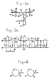
- Figure 3a partly shows the apparatus according to Figure 1 in which only the parts are shown which are important for the operation and in Figure 3b the operation is shown graphically.
- an adjustable counter 36 is actuated which after having counted a set number of marks opens the valve 37, for example an electropneumatic valve, (see also Figure 1) by which the source of pressurized air 38, is brought into open communication with a blowing nozzle 39 so that the packed articles 8 passing said blowing nozzle 39 are blown from the conveyor 9 and received in the receptacle 40.
- the counter is adjusted such that the packed articles blown from the conveyor 9 are those articles which are packed in the portion of the packing material web comprising the splice of the material webs.
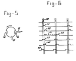
- two command disks 38 and 39 are provided which are driven in rotation synchronously with the driving means of the packing machine.
- a recess 40 is provided while an inductive sensor 41 opposes the disk so that always when the recess 40 passes the inductive sensor 41 a signal s41 is developed.
- a recess 42 is provided which is shifted by a predetermined length of arch with respect to the recess 40 in disk 38, while an inductive sensor 43 oppose the disk 39 and excites a signal s43 when recess 42 passes said sensor.
- the signals s30 excited by the photo cell 30 in response to the passing of marks 31 are continuously compared with the signals s41 as indicated in the three upper lines of Figure 6. If the signal s41 falls within the signal s30 as shown in the second line from the top in Figure 6, then the velocity of the material web needs not to be varied. However, if the signal s41 falls outside the signal s30 as indicated in the third line from the top in Figure 6, then, through a differential drive 44 the velocity of the material web 5 is varied until a signal s43 is delivered so that there occurs a certain correction time tc. If the velocity of the material web is still not obtained which is indicated by the subsequent signal s41 in comparison to a signal s30, then this velocity is changed again during the correction time tc and so on.
- the third command disk 45 is provided having two diametrically opposing recesses 46, 46', which recesses are of larger width than the recesses 40 and 42.
- an inductive sensor 47 is provided exciting a signal s47 when a recess 46 or 46' passes the sensor.
- Each signal s47 is compared with a signal s30 in the device 48 ( Figure 2), in which the length of each signal s47 is equal to the length of the signal s30 increased at both sides by a distance corresponding to a predetermined tolerance length.
- the device 48 opens the valve 37 so that the packed articles 8 being in front of the blowing nozzle 39, are blown from the conveyor 9 as said articles are packed beyond the tolerance length and have to be rejected.
- the blowing nozzle 39 continues to blow until the signal s30 falls within a signal s47 again.
Landscapes
- Engineering & Computer Science (AREA)
- Mechanical Engineering (AREA)
- Replacement Of Web Rolls (AREA)
- Containers And Plastic Fillers For Packaging (AREA)
Claims (11)
Applications Claiming Priority (2)
| Application Number | Priority Date | Filing Date | Title |
|---|---|---|---|
| NL8101588A NL8101588A (nl) | 1981-03-31 | 1981-03-31 | Werkwijze en inrichting voor het aan elkaar hechten van verpakkingsmateriaal-banen. |
| NL8101588 | 1981-03-31 |
Publications (2)
| Publication Number | Publication Date |
|---|---|
| EP0061788A1 EP0061788A1 (fr) | 1982-10-06 |
| EP0061788B1 true EP0061788B1 (fr) | 1984-08-15 |
Family
ID=19837260
Family Applications (1)
| Application Number | Title | Priority Date | Filing Date |
|---|---|---|---|
| EP82200248A Expired EP0061788B1 (fr) | 1981-03-31 | 1982-02-26 | Procédé et appareil pour raccorder des bandes de matériau d'emballage |
Country Status (4)
| Country | Link |
|---|---|
| US (1) | US4467589A (fr) |
| EP (1) | EP0061788B1 (fr) |
| DE (1) | DE3260562D1 (fr) |
| NL (1) | NL8101588A (fr) |
Cited By (1)
| Publication number | Priority date | Publication date | Assignee | Title |
|---|---|---|---|---|
| EP4126724A1 (fr) * | 2020-03-25 | 2023-02-08 | KHS GmbH | Procédé d'emballage de produits et installation d'emballage |
Families Citing this family (49)
| Publication number | Priority date | Publication date | Assignee | Title |
|---|---|---|---|---|
| AU560080B2 (en) * | 1983-05-12 | 1987-03-26 | Colgate-Palmolive Pty. Ltd. | Sheet unwinding machine with automatic ends splicing means |
| CH655077A5 (fr) * | 1984-01-27 | 1986-03-27 | Sapal Plieuses Automatiques | Dispositif d'alimentation en materiau d'emballage, d'une machine a emballer. |
| DE3527446A1 (de) * | 1985-07-31 | 1987-02-05 | Natec Reich Summer Gmbh Co Kg | Vorrichtung zum registergerechten ankleben einer von einer vorratsrolle abgezogenen, mit registermarken versehenen bedruckten bahn an eine von einer ersatzrolle abgezogene bahn |
| FR2606740B1 (fr) * | 1986-11-13 | 1989-03-24 | Erca | Procede de changement d'un produit introduit dans des recipients thermoplastiques et d'au moins un element decoratif et/ou informatif desdits recipients |
| US4800705A (en) * | 1987-07-31 | 1989-01-31 | Package Machinery Company, Bodolay/Pratt Division | Continuous form, fill, seal and separate packaging machine |
| US6176068B1 (en) | 1998-04-23 | 2001-01-23 | Bki Holding Corporation | Packaging a strip of material in layers with intervening splices |
| US6321511B1 (en) | 1988-05-20 | 2001-11-27 | Bki Holding Corporation | Packaging a strip of material with compression to reduce volume |
| DE3903792A1 (de) * | 1989-02-09 | 1990-08-16 | Tetra Pak Gmbh | Vorrichtung fuer den fliegenden wechsel einer ersten trommel auf eine zweite trommel |
| US4945707A (en) * | 1989-04-24 | 1990-08-07 | K. C. Technical Servies, Inc. | Machine and method for overwrapping cylindrical articles |
| US5440860A (en) * | 1989-06-05 | 1995-08-15 | Schreiber Foods, Inc. | Method and apparatus for forming and hermetically sealing slices of food items |
| IT1249668B (it) * | 1991-06-20 | 1995-03-09 | Cavanna Spa | Unita' per l'erogazione di materiale in foglio, ad esempio per l`erogazione di fogli di cartone o cartoncino in macchine confezionatrici automatiche. |
| ES2092668T3 (es) * | 1992-02-18 | 1996-12-01 | Sasib Packaging Italia Srl | Maquina para la produccion de bolsas de pelicula de plastico con medios para colocar el extremo de salida de una pelicula y el extremo delantero de una pelicula de reserva uno con respecto al otro. |
| IE922786A1 (en) * | 1992-02-28 | 1993-09-08 | Schreiber Foods | Method and apparatus for forming a slice of a food item¹having a heat tack seal |
| IT1258147B (it) * | 1992-09-15 | 1996-02-20 | Gd Spa | Metodo e dispositivo per la sostituzione automatica di materiale in nastro |
| US5388387A (en) * | 1993-03-12 | 1995-02-14 | Kliklok Corporation | Packaging film feeding and splicing apparatus and method |
| US6729471B2 (en) | 1997-06-16 | 2004-05-04 | Bki Holding Corporation | Packaging a strip of material with compression to reduce volume |
| US6263814B1 (en) | 1997-07-08 | 2001-07-24 | Bki Holding Corporation | Strip of material with splices and products formed therefrom |
| DE19735418A1 (de) * | 1997-08-15 | 1999-02-18 | Hassia Redatron Gmbh | Verfahren und Vorrichtung zur Zuführung einer Hüllstoffbahn zu einer Schlauchbeutel-Verpackungsmaschine |
| US6336307B1 (en) | 1997-10-09 | 2002-01-08 | Eki Holding Corporation | Method of packaging a strip of material for use in cutting into sheet elements arranged end to end |
| FI110681B (fi) * | 1998-01-02 | 2003-03-14 | Bki Holding Corp | Menetelmä rainan pakkaamiseksi |
| US6265002B1 (en) | 1998-12-18 | 2001-07-24 | Kustner Industries S.A. | Non-hermetic seal for individually wrapped food items |
| US6321512B1 (en) | 1999-03-08 | 2001-11-27 | Bki Holding Corporation | Method of packaging a strip of material |
| US6293075B1 (en) | 1999-03-08 | 2001-09-25 | Bki Holding Corporation | Packaging a strip of material |
| DE10012000A1 (de) * | 2000-03-11 | 2001-09-13 | Winkler & Duennebier Ag | Rollenwechsler für eine Vorrichtung zum Herstellen von Hygieneprodukten |
| ATE356776T1 (de) * | 2001-03-23 | 2007-04-15 | Bki Holding Corp | Verpacken einer materialbahn mit variierender breite |
| US6829876B1 (en) * | 2002-02-05 | 2004-12-14 | Robert W. Young | Process for splicing a continuous strip of packets |
| US7481033B2 (en) * | 2002-11-18 | 2009-01-27 | Ouellette Machinery Systems, Inc. | Object conveyor and bagger with sonic welded bag seams |
| JP2005035558A (ja) * | 2003-07-16 | 2005-02-10 | Fuji Photo Film Co Ltd | 包装装置及び包装方法 |
| US20050193693A1 (en) * | 2004-03-04 | 2005-09-08 | Yi-Chiu Chao | Packing machine having prepared film connecting function |
| AU2005337595B2 (en) * | 2005-10-19 | 2010-07-22 | Orihiro Engineering Co., Ltd. | Packaging device |
| US20070245679A1 (en) * | 2006-04-11 | 2007-10-25 | Conville David J | Racking and load resistant ceiling and wall construction clip and method |
| US7975633B2 (en) * | 2008-06-27 | 2011-07-12 | Miller Weldmaster Corporation | Bi-directional seaming machine |
| US8484937B1 (en) * | 2009-03-24 | 2013-07-16 | Land O'lakes, Inc. | Methods for sealing overlapped flexible packaging material using an electrical impulse through a conductive element |
| DE102011007457A1 (de) | 2011-04-15 | 2012-10-18 | Robert Bosch Gmbh | Verfahren und Vorrichtung zur Verbindung von zwei Folienbahnen |
| JP5684645B2 (ja) * | 2011-05-11 | 2015-03-18 | 株式会社イシダ | 製袋包装機 |
| CN102502301B (zh) * | 2011-11-11 | 2014-07-23 | 广东百顺纸品有限公司 | 一种卷材末端的自动接料方法 |
| CN112830310A (zh) | 2013-03-25 | 2021-05-25 | 株式会社汤山制作所 | 药剂分包装置、药剂分包纸余量判断方法和药剂分包纸卷筒 |
| DE102013105545B4 (de) * | 2013-05-29 | 2021-07-29 | Windmöller & Hölscher Kg | Erkennungsvorrichtung für den Einsatz in einer Sackfüllanlage |
| US20170008655A1 (en) * | 2015-04-03 | 2017-01-12 | Yuyama Mfg. Co., Ltd. | Medicine Inspection System, Winding Device, Feed Device, And Holder |
| WO2017065791A1 (fr) | 2015-10-16 | 2017-04-20 | Avent, Inc. | Procédé et système de mise en place de fils de nez pré-découpés au cours d'un processus de fabrication de masque facial |
| AU2015411837A1 (en) | 2015-10-16 | 2018-04-19 | O&M Halyard International Unlimited Company | Method and system for automated stacking and loading wrapped facemasks into a carton in a manufacturing line |
| MX379643B (es) | 2015-10-16 | 2025-03-11 | O&M Halyard Int Unlimited Co | Metodo y sistema para cortar y colocar tiras metalicas adaptables en un proceso de fabricacion de mascarillas. |
| MX2018004353A (es) | 2015-10-16 | 2018-05-22 | Avent Inc | Metodo y sistema para empalmar tiras metalicas adaptables en un proceso de fabricacion de mascarillas. |
| MX381816B (es) | 2015-10-16 | 2025-03-13 | O&M Halyard Int Unlimited Co | Método y sistema para apilado y carga automatizados de mascarillas envueltas en una caja de cartón en una línea de fabricación. |
| US20180208343A1 (en) * | 2015-10-16 | 2018-07-26 | Avent, Inc. | Method and System for Wrapping and Preparing Facemasks for Packaging in a Manufacturing Line |
| CN108147183A (zh) * | 2017-11-30 | 2018-06-12 | 南通大学 | 一种活动式窄条纸带压接机构及控制系统、控制方法 |
| JP7236719B2 (ja) * | 2018-10-04 | 2023-03-10 | 株式会社イシダ | 製袋包装機 |
| CN111268483B (zh) * | 2020-04-02 | 2024-08-27 | 河南省新之林机电设备有限公司 | 高速在线无胶拼接的带状薄片材料压切装置 |
| AU2021442156A1 (en) * | 2021-04-20 | 2023-10-05 | Tna Australia Pty Limited | Splice mechanism for a packaging assembly |
Family Cites Families (10)
| Publication number | Priority date | Publication date | Assignee | Title |
|---|---|---|---|---|
| DE1461217B2 (de) * | 1964-07-17 | 1971-02-04 | Jagenberg-Werke AG, 4000 Dussel dorf | Vorrichtung in einer Querschneide maschine zum Sortieren fehlerhafter Bogen bzw. Bogenpakete |
| DE1268466B (de) * | 1966-04-22 | 1968-05-16 | Siemens Ag | Verfahren zur Erzeugung von Koinzidenzimpulsen fuer den registergerecht synchronen Anschluss einer sich drehenden Rolle an eine Warenbahn |
| US3510036A (en) * | 1968-03-29 | 1970-05-05 | Bobst Champlain Inc | Inserter and splicer with register control for a reprinted web |
| FR2088733A5 (fr) * | 1970-04-22 | 1972-01-07 | Gryspeert Rene Ets | |
| CH534920A (de) * | 1971-02-24 | 1973-03-15 | Ferag Ag | Einrichtung zum zeitgleichen Zusammenführen eines kontinuierlich angetriebenen ersten Teiles mit einem intermittierend angetriebenen zweiten Teil an einer ortsfesten Stelle |
| JPS5145331Y2 (fr) * | 1972-04-13 | 1976-11-02 | ||
| US3861983A (en) * | 1973-02-12 | 1975-01-21 | Phillips Petroleum Co | Film positioning apparatus |
| US4067760A (en) * | 1976-03-24 | 1978-01-10 | General Foods Corporation | Gate control for printed web scanner |
| US4128985A (en) * | 1977-10-31 | 1978-12-12 | Package Machinery Company | Control system for package making machine |
| IT1112724B (it) * | 1979-04-24 | 1986-01-20 | Sitma Soc Italiana Macchine Au | Dispositivo per controllare la posizione della pellicola rispetto ai prodotti da imballare in una macchina da imballaggio impiegante una pellicola stampata |
-
1981
- 1981-03-31 NL NL8101588A patent/NL8101588A/nl not_active Application Discontinuation
- 1981-12-08 US US06/328,513 patent/US4467589A/en not_active Expired - Fee Related
-
1982
- 1982-02-26 EP EP82200248A patent/EP0061788B1/fr not_active Expired
- 1982-02-26 DE DE8282200248T patent/DE3260562D1/de not_active Expired
Cited By (1)
| Publication number | Priority date | Publication date | Assignee | Title |
|---|---|---|---|---|
| EP4126724A1 (fr) * | 2020-03-25 | 2023-02-08 | KHS GmbH | Procédé d'emballage de produits et installation d'emballage |
Also Published As
| Publication number | Publication date |
|---|---|
| EP0061788A1 (fr) | 1982-10-06 |
| DE3260562D1 (en) | 1984-09-20 |
| US4467589A (en) | 1984-08-28 |
| NL8101588A (nl) | 1982-10-18 |
Similar Documents
| Publication | Publication Date | Title |
|---|---|---|
| EP0061788B1 (fr) | Procédé et appareil pour raccorder des bandes de matériau d'emballage | |
| EP2969518B1 (fr) | Procédé pour exécuter des tâches multiples sur une bande de matériau | |
| US6086694A (en) | High speed web machine | |
| EP0296290B1 (fr) | Contrôle de produits-hors-registre pour machine d'enveloppement à vitesse élevée | |
| US6219993B1 (en) | Zipper sealer machine | |
| CA2273419C (fr) | Methode de fabrication de sacs en aluminium et appareil pour fabriquer les sacs | |
| EP0614809B1 (fr) | Dispositif et procédé pour alimenter et raccorder un film d'emballage | |
| EP1203718B1 (fr) | Machine de fabrication, de remplissage et scellage de sacs | |
| JP3073001B2 (ja) | ラベル貼り機のためのオンラインエンボス装置 | |
| US6217497B1 (en) | Stand-up apparatus for producing flexible pouches | |
| JPS643782B2 (fr) | ||
| US5117608A (en) | Pouch profile detector | |
| US6234230B1 (en) | Device for continuously applying self-adhesive handles to moving articles | |
| US5021039A (en) | Apparatus for manufacturing air cushion dispatch packages | |
| GB2253203A (en) | Changing web rolls whilst feeding user machine | |
| EP1894846B1 (fr) | Appareil pour la création de paquets à ouverture facile | |
| US6834826B2 (en) | Film connecting/feeding apparatus | |
| US6550225B1 (en) | Method and apparatus for obtaining individual web sections from a web of sheet material | |
| JPH01145968A (ja) | 帯状材の搬送位置決め装置 | |
| US5304275A (en) | Applying a reinforcement film to sheets | |
| WO2026038072A1 (fr) | Appareil d'emballage | |
| JP2003128003A (ja) | 充填包装機 | |
| JPH06155637A (ja) | 製袋機におけるフィルム送り量の誤差修正方法 |
Legal Events
| Date | Code | Title | Description |
|---|---|---|---|
| PUAI | Public reference made under article 153(3) epc to a published international application that has entered the european phase |
Free format text: ORIGINAL CODE: 0009012 |
|
| AK | Designated contracting states |
Designated state(s): CH DE GB NL |
|
| 17P | Request for examination filed |
Effective date: 19830223 |
|
| GRAA | (expected) grant |
Free format text: ORIGINAL CODE: 0009210 |
|
| AK | Designated contracting states |
Designated state(s): CH DE GB LI NL |
|
| REF | Corresponds to: |
Ref document number: 3260562 Country of ref document: DE Date of ref document: 19840920 |
|
| PLBE | No opposition filed within time limit |
Free format text: ORIGINAL CODE: 0009261 |
|
| STAA | Information on the status of an ep patent application or granted ep patent |
Free format text: STATUS: NO OPPOSITION FILED WITHIN TIME LIMIT |
|
| 26N | No opposition filed | ||
| PGFP | Annual fee paid to national office [announced via postgrant information from national office to epo] |
Ref country code: GB Payment date: 19940216 Year of fee payment: 13 |
|
| PGFP | Annual fee paid to national office [announced via postgrant information from national office to epo] |
Ref country code: DE Payment date: 19940224 Year of fee payment: 13 Ref country code: CH Payment date: 19940224 Year of fee payment: 13 |
|
| PGFP | Annual fee paid to national office [announced via postgrant information from national office to epo] |
Ref country code: NL Payment date: 19940228 Year of fee payment: 13 |
|
| PG25 | Lapsed in a contracting state [announced via postgrant information from national office to epo] |
Ref country code: GB Effective date: 19950226 |
|
| PG25 | Lapsed in a contracting state [announced via postgrant information from national office to epo] |
Ref country code: LI Effective date: 19950228 Ref country code: CH Effective date: 19950228 |
|
| PG25 | Lapsed in a contracting state [announced via postgrant information from national office to epo] |
Ref country code: NL Effective date: 19950901 |
|
| GBPC | Gb: european patent ceased through non-payment of renewal fee |
Effective date: 19950226 |
|
| NLV4 | Nl: lapsed or anulled due to non-payment of the annual fee |
Effective date: 19950901 |
|
| PG25 | Lapsed in a contracting state [announced via postgrant information from national office to epo] |
Ref country code: DE Effective date: 19951101 |