EP0061874B1 - Verfahren zum in situ Ausbeulen von Fahrzeugteilen - Google Patents
Verfahren zum in situ Ausbeulen von Fahrzeugteilen Download PDFInfo
- Publication number
- EP0061874B1 EP0061874B1 EP82301429A EP82301429A EP0061874B1 EP 0061874 B1 EP0061874 B1 EP 0061874B1 EP 82301429 A EP82301429 A EP 82301429A EP 82301429 A EP82301429 A EP 82301429A EP 0061874 B1 EP0061874 B1 EP 0061874B1
- Authority
- EP
- European Patent Office
- Prior art keywords
- vessel
- dented area
- area
- dented
- air
- Prior art date
- Legal status (The legal status is an assumption and is not a legal conclusion. Google has not performed a legal analysis and makes no representation as to the accuracy of the status listed.)
- Expired
Links
Images
Classifications
-
- B—PERFORMING OPERATIONS; TRANSPORTING
- B21—MECHANICAL METAL-WORKING WITHOUT ESSENTIALLY REMOVING MATERIAL; PUNCHING METAL
- B21D—WORKING OR PROCESSING OF SHEET METAL OR METAL TUBES, RODS OR PROFILES WITHOUT ESSENTIALLY REMOVING MATERIAL; PUNCHING METAL
- B21D1/00—Straightening, restoring form or removing local distortions of sheet metal or specific articles made therefrom; Stretching sheet metal combined with rolling
- B21D1/06—Removing local distortions
- B21D1/08—Removing local distortions of hollow bodies made from sheet metal
-
- Y—GENERAL TAGGING OF NEW TECHNOLOGICAL DEVELOPMENTS; GENERAL TAGGING OF CROSS-SECTIONAL TECHNOLOGIES SPANNING OVER SEVERAL SECTIONS OF THE IPC; TECHNICAL SUBJECTS COVERED BY FORMER USPC CROSS-REFERENCE ART COLLECTIONS [XRACs] AND DIGESTS
- Y10—TECHNICAL SUBJECTS COVERED BY FORMER USPC
- Y10S—TECHNICAL SUBJECTS COVERED BY FORMER USPC CROSS-REFERENCE ART COLLECTIONS [XRACs] AND DIGESTS
- Y10S72/00—Metal deforming
- Y10S72/705—Vehicle body or frame straightener
Definitions
- This invention relates to the in situ removal of dents in components, such as body panels and fuel tanks of vehicle such as passenger cars, vans, commercial vehicles and motorbikes.
- U.S. Specification No. 2,804,118 discloses a bellows type pneumatic jack for positioning behind a dented body panel and application of pressure to the dent via a dolly plate.
- the device is of limited versatility and can only apply pressure at the apex of the dent.
- I provide a method for the in situ removal of dents in components of vehicles, comprising positioning in the cavity, between a dented area and a support structure provided by the inner support structure of the vehicle and/or a separately provided backing member, a closed air-impervious inflatable vessel, said vessel being of a size to more than cover the dented area and to accommodate itself to the surface configuration of the dented area upon partial inflation, and introducing air under pressure into said vessel, whereby the vessel fills the cavity behind the dented area and accommodates itself to the surface configuration of the dented area; and introducing additional air under pressure so that the vessel swells outwardly to restore the dented area substantially to its original form.
- the vessel After use the vessel can be removed for reuse simply by releasing the pressure.
- the vessel may be of natural or synthetic rubber or, more preferably, of the more abrasion resistant polyurethane proofed nylon of uniform thickness throughout (such as 1/16" (0.16cm) thick for polyurethane proofed nylon (RTM)) and is shaped and dimensioned to be accommodated in the cavity between the dented area of the body panel and the support structure therebehind.
- RTM polyurethane proofed nylon
- One convenient shape is substantially cylindrical when inflated and comprises a pair of circular end panels joined by a continuous side wall panel.
- a further preferred shape in uninflated form comprises a pair of overlying flat panels sealed at the edges to form a closed bag.
- Such a bag suitably rectangular, can be of any suitable size and can .conveniently be folded if desired to alter its size.
- Any suitable working pressure can be used to remove the dents, a pressure of 2 to 10 Ibs/sq.in (0.14 to 0.71 kg/sq.cm) being suitable for most purposes. Of course some dents will require lower pressures than others and much also depends on the material, e.g. metal or fibreglass, being treated.
- the vessel may of course be of other shapes. Appropriately a number of differently shaped vessels would be available, that of the shape most convenient for removal of a dent or dents being chosen on any occasion.
- the vessel chosen will be of a size that more than covers the dented area.
- a non-inflated vessel as described and of a shape appropriate to the damaged area of a body panel of a vehicle is inserted through an access opening into the space between the damaged area and the support structure.
- the vessel is inflated and accommodates itself to the surface configuration of the damaged area. Additional pressurised air causes the vessel to distend and flatten out the dent or dents from the inside, thereby to restore the body panel to its original form.
- the above described device is advantageous in that it removes or assists in removing dents with greater accuracy and causes less panel stretching than with methods employed heretofore. It can also obviate the necessity in a majority of occasions for using conventional mechanical and/or hydraulic wedges. Furthermore there is a great reduction in the time needed to repair the dent. Thus even though some panel beating may be required to finish the job, it is estimated that a job conventionally taking about 2 hours may be reduced to 15 or 20 minutes.
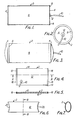
- the device shown comprises a vessel 2 suitably of polyurethane proofed nylon of 1/16" (0.16cm) thickness.
- Vessel 2 has two circular end wall panels 4 joined by a continuous side wall panel 6 in the form of a cylinder formed by curving a flat sheet and welding or otherwise suitably connecting the longitudinal abutting edges of the sheet.
- the panels 4 and 6 are suitably joined to make a closed container, for example by the use of welded sealing strips 8.
- An inflation tube 10 is suitably welded via a flange 17 to one end panel 4, but could of course be positioned elsewhere on the device. When uninflated the vessel 2 will lie in a flattened, crumpled condition.
- the vessel 6 in its uninflated condition, is placed behind a body panel of a vehicle having a dent to be repaired.
- the vessel 2 will normally be positioned between the body panel and the inner support structure of the vehicle. However if there is no such inner support structure adjacent the dent to be mended, any suitable backing member, such as a suitably sized piece of wood, can be wedged behind the vessel.
- the vessel 2 can be positioned with an end face 4 or the panel 6 against the dent, dependent on the size of the dent and the shape of the space available behind the dent.
- the vessel 2 should be sized to more than cover the dented area.
- Air under pressure is then introduced through tube 10 into the vessel 2 so that it expands to the shape shown in Figure 3 and exerts pressure on the dent while conforming to the contour of the dent and returning the dent towards its original shape.
- the pressure is released and the vessel 2 collapses and can be removed for subsequent re-use. Further finishing by panel beating may be carried out if necessary but the time for the repair will in any case have been greatly reduced. Any further panel beating may be carried out with the vessel still in place or after its removal, whichever is more convenient.
- the device shown in Figures 4 to 7 conprises a vessel 2 of the same material as that of Figures 1 to 3, which in collapsed form as shown in Figures 4 and 5 comprises two rectangular overlying panels 12 secured by any suitable means such as welding along one pair of opposite edges 14.
- the other pair of opposite edges 16 may be secured in the same way or may have sealing or reinforcing strips 18 secured thereover, suitably by welding as shown in Figure 5 so that a closed vessel is formed.
- One panel 12 has an inflation tube 10 affixed thereto.
- vessel 2 inflates to the conformation shown in Figures 6 and 7 with a midsection of oval cross section, best seen in Figure 7 and concave ends 20 as shown in Figure 6.
- the vessel 2 will be introduced behind a dent as described for Figures 1 to 3 with a panel 12 overlying the dent. If the vessel 2 is too big, because of its lie-flat conformation in the uninflated state, it can be folded so that the operative portion of the vessel becomes smaller.
- the vessel shown in Figures 4 to 7 is thus versatile and easy to store.
- the device can clearly be formed-in a variety of sizes and shapes to suit the size and variety of possible dents to be mended.
- vessels which inflate to a substantially square or cuboid shape.
- Examples of vessels of the type shown in Figures 1 to 3 have end panels of diameter 3" (7.62cm), 9" (22.86cm) or 12" (30.48cm) with lengths respectively of 6" (15.24cm), 24" (60.96cm) and 6" (15.24cm).
- vessels of the type shown in Figures 4 to 7 are of 30" x 18" (76.2 x 45.72cm), 38" x 18" (96.52 x 45.72cm), 34" x 22" (86.36 x 55.88cm), 38" x 22" (96.52 x 55.88cm) and 15" x 24" (38.1 x 60.96cm).
- vessels which inflate to a substantially cuboid shape may be of dimensions 12" x 12" x 6" (30.48 x 30.48 x 15.24cm) or 6" x 6" x 4" (15.24 x 15.24 x 10.66cm).
Landscapes
- Engineering & Computer Science (AREA)
- Mechanical Engineering (AREA)
- Refuge Islands, Traffic Blockers, Or Guard Fence (AREA)
- Air Bags (AREA)
- Filling Or Discharging Of Gas Storage Vessels (AREA)
Claims (8)
Applications Claiming Priority (2)
| Application Number | Priority Date | Filing Date | Title |
|---|---|---|---|
| GB8109610 | 1981-03-26 | ||
| GB8109610 | 1981-03-26 |
Publications (3)
| Publication Number | Publication Date |
|---|---|
| EP0061874A2 EP0061874A2 (de) | 1982-10-06 |
| EP0061874A3 EP0061874A3 (en) | 1983-06-22 |
| EP0061874B1 true EP0061874B1 (de) | 1986-07-23 |
Family
ID=10520693
Family Applications (1)
| Application Number | Title | Priority Date | Filing Date |
|---|---|---|---|
| EP82301429A Expired EP0061874B1 (de) | 1981-03-26 | 1982-03-19 | Verfahren zum in situ Ausbeulen von Fahrzeugteilen |
Country Status (5)
| Country | Link |
|---|---|
| US (1) | US4453391A (de) |
| EP (1) | EP0061874B1 (de) |
| CA (1) | CA1182032A (de) |
| DE (1) | DE3272076D1 (de) |
| IE (1) | IE52814B1 (de) |
Families Citing this family (3)
| Publication number | Priority date | Publication date | Assignee | Title |
|---|---|---|---|---|
| DE4406147C2 (de) * | 1994-02-25 | 1998-07-16 | Roth Matthias | Vorrichtung zum Ausbeulen eines plastisch verformten Teils |
| US6176113B1 (en) | 1999-02-19 | 2001-01-23 | White, Iii Harold J. | Inflatable device for removing dents in components of vehicles |
| CN113635156B (zh) * | 2021-10-18 | 2021-12-24 | 张家港南光包装容器再生利用有限公司 | 一种开口金属桶整形装置 |
Family Cites Families (6)
| Publication number | Priority date | Publication date | Assignee | Title |
|---|---|---|---|---|
| US2804118A (en) * | 1954-09-13 | 1957-08-27 | Irvin L Bayerkohler | Pneumatic bellows type jacks |
| US3026541A (en) * | 1959-10-27 | 1962-03-27 | Adolf R Murat | Pneumatic lifter for bed patient |
| US3180130A (en) * | 1962-04-09 | 1965-04-27 | Crose Perrault Equipment Corp | Mandrel for preventing wrinkling of pipes during bending thereof |
| JPS4931052A (de) * | 1972-07-24 | 1974-03-20 | ||
| AU8102075A (en) * | 1974-05-24 | 1976-11-11 | Hasegawa Haguruma Kk | Bladder type car jack using exhaust |
| US4171631A (en) * | 1977-03-07 | 1979-10-23 | Butts Clifford L | Method of restoring deformed outer vehicle panel to its original contour |
-
1982
- 1982-03-19 EP EP82301429A patent/EP0061874B1/de not_active Expired
- 1982-03-19 DE DE8282301429T patent/DE3272076D1/de not_active Expired
- 1982-03-23 US US06/361,045 patent/US4453391A/en not_active Expired - Fee Related
- 1982-03-25 IE IE701/82A patent/IE52814B1/en unknown
- 1982-03-26 CA CA000399549A patent/CA1182032A/en not_active Expired
Also Published As
| Publication number | Publication date |
|---|---|
| DE3272076D1 (en) | 1986-08-28 |
| IE52814B1 (en) | 1988-03-16 |
| CA1182032A (en) | 1985-02-05 |
| EP0061874A3 (en) | 1983-06-22 |
| US4453391A (en) | 1984-06-12 |
| EP0061874A2 (de) | 1982-10-06 |
Similar Documents
| Publication | Publication Date | Title |
|---|---|---|
| US5884659A (en) | Portable tubeless tire inflating system | |
| US3334864A (en) | Tire servicing apparatus | |
| US2200133A (en) | Method of and means for straightening out deformed automobile bodies and the like | |
| US5456302A (en) | Process and apparatus for seating tubeless tires | |
| CA2141641A1 (en) | Method and Apparatus for Restraining a Vehicle Occupant | |
| US2663348A (en) | Tire inflator | |
| CA2141726A1 (en) | Method and Apparatus for Inflating an Inflatable Vehicle Occupant Restraint | |
| JPS61254497A (ja) | 空気式ジヤツキ及びその製造方法 | |
| CA2078086A1 (en) | Pneumatic Sealing Device for Waste Disposal Systems | |
| US6176113B1 (en) | Inflatable device for removing dents in components of vehicles | |
| US4453391A (en) | Device for the in situ removal of dents in components of vehicles | |
| US5782737A (en) | Method of folding a vehicle safety airbag | |
| US4171631A (en) | Method of restoring deformed outer vehicle panel to its original contour | |
| EP0865841B1 (de) | Verfahren zur Streckformung von Metallhohlkörpern | |
| US2741093A (en) | Core for driving pile shells | |
| JP3940821B2 (ja) | 損傷した金属製及びプラスチック製部材を矯正するための装置及び方法 | |
| WO2006044483A2 (en) | Seamless inflatable bag with multiple applications | |
| US2717849A (en) | Method and apparatus for making compartmented tubular devices | |
| US5005627A (en) | Device for sealing between 4 tubeless tire and a rim during tire inflation process | |
| US5431039A (en) | Fender well press | |
| US2903037A (en) | Traction attachment for wheels | |
| US3260295A (en) | Automobile wheel and inner tube | |
| US3787953A (en) | Spare tire removal system | |
| US2864424A (en) | Motor vehicle tire construction | |
| US2950751A (en) | Emergency tire |
Legal Events
| Date | Code | Title | Description |
|---|---|---|---|
| PUAI | Public reference made under article 153(3) epc to a published international application that has entered the european phase |
Free format text: ORIGINAL CODE: 0009012 |
|
| AK | Designated contracting states |
Designated state(s): BE DE FR GB NL SE |
|
| PUAL | Search report despatched |
Free format text: ORIGINAL CODE: 0009013 |
|
| AK | Designated contracting states |
Designated state(s): BE DE FR GB NL SE |
|
| 17P | Request for examination filed |
Effective date: 19831202 |
|
| GRAA | (expected) grant |
Free format text: ORIGINAL CODE: 0009210 |
|
| AK | Designated contracting states |
Kind code of ref document: B1 Designated state(s): BE DE FR GB NL SE |
|
| PG25 | Lapsed in a contracting state [announced via postgrant information from national office to epo] |
Ref country code: NL Effective date: 19860723 Ref country code: BE Effective date: 19860723 |
|
| PG25 | Lapsed in a contracting state [announced via postgrant information from national office to epo] |
Ref country code: SE Effective date: 19860731 |
|
| REF | Corresponds to: |
Ref document number: 3272076 Country of ref document: DE Date of ref document: 19860828 |
|
| ET | Fr: translation filed | ||
| NLV1 | Nl: lapsed or annulled due to failure to fulfill the requirements of art. 29p and 29m of the patents act | ||
| PLBE | No opposition filed within time limit |
Free format text: ORIGINAL CODE: 0009261 |
|
| STAA | Information on the status of an ep patent application or granted ep patent |
Free format text: STATUS: NO OPPOSITION FILED WITHIN TIME LIMIT |
|
| 26N | No opposition filed | ||
| PGFP | Annual fee paid to national office [announced via postgrant information from national office to epo] |
Ref country code: GB Payment date: 19910318 Year of fee payment: 10 |
|
| PGFP | Annual fee paid to national office [announced via postgrant information from national office to epo] |
Ref country code: FR Payment date: 19910329 Year of fee payment: 10 |
|
| PGFP | Annual fee paid to national office [announced via postgrant information from national office to epo] |
Ref country code: DE Payment date: 19910330 Year of fee payment: 10 |
|
| PG25 | Lapsed in a contracting state [announced via postgrant information from national office to epo] |
Ref country code: GB Effective date: 19920319 |
|
| GBPC | Gb: european patent ceased through non-payment of renewal fee | ||
| PG25 | Lapsed in a contracting state [announced via postgrant information from national office to epo] |
Ref country code: FR Effective date: 19921130 |
|
| PG25 | Lapsed in a contracting state [announced via postgrant information from national office to epo] |
Ref country code: DE Effective date: 19921201 |
|
| REG | Reference to a national code |
Ref country code: FR Ref legal event code: ST |