EP0061896A1 - A forage harvester - Google Patents
A forage harvester Download PDFInfo
- Publication number
- EP0061896A1 EP0061896A1 EP82301563A EP82301563A EP0061896A1 EP 0061896 A1 EP0061896 A1 EP 0061896A1 EP 82301563 A EP82301563 A EP 82301563A EP 82301563 A EP82301563 A EP 82301563A EP 0061896 A1 EP0061896 A1 EP 0061896A1
- Authority
- EP
- European Patent Office
- Prior art keywords
- chassis
- container
- forage
- chassis part
- forage harvesting
- Prior art date
- Legal status (The legal status is an assumption and is not a legal conclusion. Google has not performed a legal analysis and makes no representation as to the accuracy of the status listed.)
- Granted
Links
- 239000004459 forage Substances 0.000 title claims abstract description 97
- 238000003306 harvesting Methods 0.000 claims abstract description 64
- 230000008878 coupling Effects 0.000 claims description 27
- 238000010168 coupling process Methods 0.000 claims description 27
- 238000005859 coupling reaction Methods 0.000 claims description 27
- 239000012530 fluid Substances 0.000 claims description 7
- 230000002787 reinforcement Effects 0.000 description 6
- 241001124569 Lycaenidae Species 0.000 description 2
- 230000000694 effects Effects 0.000 description 2
- 238000000926 separation method Methods 0.000 description 2
- 230000004308 accommodation Effects 0.000 description 1
- 230000004323 axial length Effects 0.000 description 1
- 238000010276 construction Methods 0.000 description 1
- 238000007599 discharging Methods 0.000 description 1
- 230000005484 gravity Effects 0.000 description 1
- 238000003780 insertion Methods 0.000 description 1
- 230000037431 insertion Effects 0.000 description 1
- 244000144972 livestock Species 0.000 description 1
- 239000000463 material Substances 0.000 description 1
- 238000000034 method Methods 0.000 description 1
- 230000003014 reinforcing effect Effects 0.000 description 1
- 238000007789 sealing Methods 0.000 description 1
- 230000001932 seasonal effect Effects 0.000 description 1
- 238000006467 substitution reaction Methods 0.000 description 1
Images


Classifications
-
- A—HUMAN NECESSITIES
- A01—AGRICULTURE; FORESTRY; ANIMAL HUSBANDRY; HUNTING; TRAPPING; FISHING
- A01D—HARVESTING; MOWING
- A01D90/00—Vehicles for carrying harvested crops with means for selfloading or unloading
- A01D90/02—Loading means
Definitions
- the present invention relates in general to a forage harvesting machine, and in particular to a machine capable of being used not only for forage harvesting but also for other purposes.
- Two main kinds of forage harvester are known, of which a first type is constructed as an agricultural machine for cutting and/or chopping the crop and for conveying it to a separate trailer, and the second type is constructed as a combined container and forage harvesting mechanism.
- forage harvesting mechanism will be understood to refer to a mechanism for cutting and/ or chopping and/ conveying cut and/or chopped forage crop to a container. Both of these known types of machine are arranged to be drawn by a separate tractor vehicle.
- the first type of forage harvester mentioned above requires a separate trailer towed behind it or behind a second tractor, whilst in the second type the container is provided as a component part of the machine which thus comprises the container which is carried on a wheeled chassis, and the forage harvesting mechanism.
- Discharge of forage from the container of a forage harvester of the second type mentioned above can be effected either by tipping the container with respect to the chassis, or by means of a discharge conveyor, such as a screw auger conveyor, which operates to discharge the cut or chopped forage crop laterally or rearwardly of the container.
- a discharge conveyor such as a screw auger conveyor
- the forage harvesting mechanism is permanently fixed to the chassis, and although in some known machines the mechanism is movable between a working and a travelling position there is no provision for removal of the forage harvesting mechanism except by dismantling the machine as a whole. This means that the machine can only be used for the single purpose of cutting and carting forage and as this is a seasonal occupation the considerable investment involved in such machinery is unused for the major part of the year.
- the primary object of the present invention is to provide a forage harvester machine which can be adapted for other uses thereby making more effective use of the investment in the machine and extending its usefulness throughout the year.
- a forage harvesting machine adapted to be drawn behind a tractor vehicle and to collect a forage crop in a container carried by wheeled support means and having a forage harvesting mechanism operable to deliver cut and/or chopped forage crop into the container when the machine is operated, is characterised in that the forage harvesting mechanism is releasably mounted on the wheeled support for the container, which latter can be adapted for use as an independent trailer when the forage harvesting mechanism is removed therefrom.
- Such independent use may include, for example, conveying of grain or other bulk materials for which agricultural transport is required.
- the trailer part of the machine can thus be used throughout the year and adapted for its forage harvesting purpose by the addition of the forage harvesting mechanism at the appropriate time of year. This avoids the necessity for the whole of the forage harvester to be idle throughout the year so that the capital invested in the machine can be better utilised.
- a trailer vehicle having a chassis carried on ground-engaging wheels and a container supported on the chassis, characterised in that there are provided means for removably mounting a forage harvesting mechanism on the chassis, the forage harvesting mechanism being operable to cut and/or chop a forage crop as the trailer is drawn over the crop, and to convey the cut and/or chopped forage crop to the container of the trailer.
- the forage harvesting mechanism must have means for coupling a suitable drive shaft thereto from the tractor, and thiscoupling preferably accommodates changes in the position of the forage harvesting mechanism between a lowered, cutting position and a raised, transport position on the trailer chassis.
- the wheeled support for the container comprises a chassis including a first chassis part on which the container is carried, and a second chassis part on which the forage harvesting mechanism is releasably mounted, the said second chassis part being movable with respect to the first chassis part between a first position in which the machine is adapted to receive and support the forage harvesting mechanism and a second position in which it is adapted for use as an independent trailer.
- the longitudinal extension of the chassis is preferably provided by means of telescopically extendable longitudinal chassis members.
- the said telescopically extendable longitudinal chassis members may be channel section members which can partly surround respective relatively fixed longitudinal chassis members of the first chassis part which are carried by the wheels of the trailer vehicle.
- the telescopically extendable longitudinal chassis members and the fixed chassis members may be interconnected by a rack and pinion coupling mechanism so arranged that rotation of the pinion of the rack and pinion coupling mechanism causes relative longitudinal movement between the said fixed chassis members and the said extendable chassis members.
- the rack of the rack and pinion coupling mechanism may be formed on or carried by the fixed chassis members whilst the pinion cooperating therewith may be mounted so as to be rotatable on, but longitudinally fixed with respect to the extendable chassis members.
- the rack of the rack and pinion coupling may be secured on or formed by one or more of the extendable chassis members, whilst the or each pinion of the rack and pinion coupling may be mounted on one of the fixed chassis members for rotation therewith.
- chassis members there are two longitudinally extendable chassis members, one on either side of the fixed part of the chassis itself, each being coupled to an associated longitudinal chassis member by a respective rack and pinion coupling, the pinions of the two rack and pinion couplings being mounted on a common shaft for rotation together.
- the longitudinally movable chassis members are extended and locked in position to provide accommodation for the forage harvesting mechanism which can be mounted on suitable mounting brackets or plates provided on the movable chassis members.
- the cutter mechanism can be simply removed and the chassis retracted to enable the trailer to be used for _any other purpose.
- the discharge of forage from the container may be effected either by tipping the container with respect to the chassis, or by means of a discharge conveyor located in the container.
- the container is a tipping container since a screw' discharge auger may constitute a disadvantage for use of the trailer for other purposes particularly if, for example, it may be desired to carry livestock in the trailer.
- a forage harvesting machine is characterised in that the wheeled support for the container comprises a chassis including a first chassis part on which the container is carried and a second chassis part on which the forage harvesting mechanism is mounted, the second chassis part including a towing coupling and being removably connected to the first chassis part, there being provided a third chassis part having a towing coupling thereon and which is interchangeable with the second chassis part to adapt the machine for use as an independent trailer.
- the forage harvesting machine may be more particularly characterised in that the said first chassis part includes a container support frame pivotally mounted on a twin-wheel bogie and there are provided means for locking the container support frame with respect to the bogie to prevent relative turning movement thereof in at least one directional sense.
- the said locking means include an adjustable wedge which can be.interposed between a main frame member of the bogie and the container support frame of the first chassis part, on one side of the pivotal connection between the said container support frame and the bogie.
- This latter embodiment may be further characterised in that the container is pivotally connected to the container support frame at or adjacent the rear thereof so that the container is tippable with respect to the chassis, a fluid pressure actuator for controlling the inclination of the container with respect to the chassis being provided, this actuator having a coupling by which it can be connected to a fluid pressure source on a tractor vehicle, means being provided for locking the container in an elevated or tipped position with respect to the chassis in such a way that the trailer is balanced on the bogie when the lockirg wedge is interposed between the said container support frame and the bogie itself.
- the machine illustrated generally comprises a trailer part indicated with the reference numeral 11, and a forage harvesting mechanism generally indicated 12.
- the forage harvesting mechanism can be one of a number of commercially available types and the construction of it will not be described in more detail herein as it does not form part of the present invention.
- the trailer part 11 comprises a lower chassis part generally indicated 13 mounted on a pair of ground-engaging wheels 14 and carrying an upper chassis part generally indicated 15 on which is mounted a container 16 having four generally upright sides and an open top.
- the rear wall of the container 16 is pivoted at its upper edge to the side walls, and can be swung open from the bottom by means of a lever arrangement 17 operated by a cord 18.
- the upper chassis part 15 is pivoted to the lower chassis part 13 at the rear end thereof, for which purpose the upper chassis part :.arries two downwardly projecting lugs 19 which are rigidly secured to the upper chassis part 15 and pivoted to the lower chassis part 13 by pivots 20.
- Means such as an hydraulic ram are connected beiween the upper and lower chassis parts forward of the road wheels 14 for controlling the angular or entation of the upper chassis part 15 with respect to the lower chassis part 13 whereby to effect tipping o: the container 16 for emptying its contents when required.
- the cord 18 is secured at its lower end to the corner chassis part so that the rear wall or tail gate of the container 16 is opened automatically as the container 16 is tipped.
- the container 16 could be provided with a screw auger or other conveyor for discharging its contents either laterally or rearwardly, for which purpose the container 16 would be provided with an opening and a discharge chute either in a side wall or in the rear wall.
- the lower chassis part 13 comprises two main longitudinal beam members 21 interconnected by a number of transverse struts 22, only one of which is shown in Figure 3.
- the beam members 21 are channel section members located with the open side of the channel facing outwardly, that is with the web of the channel facing the other longitudinal fixed beam member 21.
- the upper flange of the beam members 21 carries a plurality of spaced stub columns 23 which form supports for the longitudinal members of the upper chassis part 15 when this is lowered to its normal working position.
- a forward portion 13a of the lower chassis part 13, is extendable with respect to the fixed portion carrying the ground engaging wheels 14, and comprises two box section longitudinal members 24 joined at their forward ends by a transverse strut 25 carrying a central forward projecting arm 26 to the lower side of which is connected a box section support 26 carrying a telescopically adjustable towing coupling 28 which, in the illustrated embodiment, comprises a ring for an agricultural coupling.
- the strut 26 is reinforced by triangular reinforcing plates 29 at its coupling with the transverse strut 25 to accommodate transverse loads.
- the two longitudinally extendable box section members 24 are of dimensions to fit slidingly within the channel section fixed longitudinal members 21, and they carry reinforcement plates 30 on the outer faces thereof.- Towards the rear end of the reinforcement plates 30 there are secured respective upstanding lugs 31 having aligned apertures through which passes a shaft 32 which is secured in one of the lugs and projects through the other with a splined end 33.
- the shaft 32 carries a pair of straight cut pinions 34 at a position slightly inboard of the lugs 31, which pinions mesh with respective racks 35 formed on the upper edge of rack plates 36 which are secured to the inner faces of the fixed longitudinal chassis members 21 at positions slightly rearwardly of the forward end of these chassis members.
- the longitudinal fixed chassis members 21, the extendable chassis members 24 and the reinforcement plates 30 have two sets of holes which are aligned with one another in the extended and retracted positions of the chassis.
- a bolt 37 passes through these aligned holes to fix the chassis in its extended or its retracted position.
- a suitable circular reinforcement plate is secured over the aligned holes in the form of a washer.
- a similar locking bolt is provided at the rear end of the reinforcement plate 30, and indicated 39 in the drawings.
- the forage harvesting mechanism can be mounted, on lugs 40 carried by the extendable part of the chassis for this purpose, and the equipment is then usable as a forage harvester to be towed, via the towing coupling 28, by a tractor vehicle which also drives the forage chopping mechanism via a power take-off shaft and coupling (not shown).
- the forage chopping mechanism 12 cuts and chops the crop and delivers it through a chute 12a into the open upper end of the container 16 from which it can be discharged by tipping the container 16 on the upper chassis 15 with respect to the lower chassis 13.
- the forage harvesting mechanism 12 When the machine is no longer required for forage harvesting the forage harvesting mechanism 12 can be removed from the lugs 40.
- the securing bolts 37, 39 can then be removed, and by means of a suitable tool engaged on the splined end 33 of the shaft 32 the two pinions 34 can be caused to rotate to carry them along the rack 35 on the rack plate 36.
- a forage harvester having a twin wheel bogie is illustrated.
- the bogie has two axles 41, 42 each with a respective pair of ground-engaging wheels 43, 44 at each end thereof.
- the axles are interconnected by respective main frame members 45 of the bogie, which are pivotally connected at an intermediate point 46. to a lug 47 carried by a fixed longitudinal member 48 of a chassis main frame.
- the chassis is formed in two parts, a first part of which the frame member 48 constitutes a longitudinal beam, and a second part generally indicated 49 which supports a forage harvesting mechanism generally indicated 50 by means of a system of linkage levers 51, 52 which constitute a quadrilateral linkage between the forage harvester mechanism 50 and the second chassis part 49.
- a fluid pressure actuator 53 interconnects the second chassis part 49 and the forage harvester mechanism 50, and extension and retraction of this actuator effects raising and lowering of the forage harvester mechanism 50 with respect to the chassis of the forage harvester machine.
- the quadrilateral linkage 51, 52 ensures that the forage harvesting mechanism is tilted slightly as it is raised so that a chute 73 is inclined slightly forwardly as the mechanism is raised and a coupling 54 for a connection to a power take-off shaft of a tractor vehicle follows a curved path centred on the coupling point on a tractor vehicle so that raising and lowering of the forage harvesting mechanism can be effected with the tractor vehicle connected by the coupling shaft to the forage harvesting mechanism.
- a container 55 in the form of an open sided box is pivotally mounted by a pivot 56 to the rear of the first chassis part 48 and a fluid pressure actuator 57, preferably an hydraulic actuator, interconnects the first chassis part 48 with a lower support frame 5 8 of the container 55.
- a fluid pressure actuator 57 preferably an hydraulic actuator
- the chassis of the forage harvester is thus formed in two parts, comprising the first chassis part 48 supported via the bogie on the ground engaging wheels 43, 44 and a second chassis part 49 which carries the forage harvesting mechanism 50 and includes a coupling attachment 59 for connecting the harvester to a towing vehicle (not shown) and a jockey wheel 60 for maintaining the harvester in a desired orientation when the forage harvesting mechanism 50 is in its raised position (so that the wheels of the forage harvesting mechanism are lifted from the ground) and the harvester is not coupled to a tractor vehicle.
- the second chassis part 49 is connected to the first chassis part 48 by means of two lugs 61, 62 on each longitudinal frame member of the second chassis part 49, these having holes therein through which pass respective bolts which also pass through cooperating aligned holes (not shown) in the main frame members 48 of the first chassis part.
- a strut 63 pivotally mounted on the underside of the container support frame 58 is engagable on the first chassis part 48 to hold the container 55 in the tipped position in which it is illustrated in Figure 5, corresponding to extension of the hydraulic actuator 57 even when the connection to the fluid pressure source on the tractor vehicle is disconnected. This serves as a safety feature and reduces the sealing requirements on the coupling to the actuator 57.
- a plate 64 and locking pin 65 are provided for locking the forage harvesting mechanism 50 in its lowered position where its own ground-engaging wheels are in contact with the ground so that when the first and second trailer parts are separated by releasing the bolts passing through the holes in the lugs 61, 62 the second trailer part can be withdrawn and conveyed on these ground-engaging wheels and the jockey wheel 60.
- first trailer part 48 would now turn about the pivot 46 with respect to the bogie 45 and, in order to prevent this an adjustable locking wedge 66 is provided, this being interpositioned between the forward end of the main bogie frame member 45 and the main frame member 48 of the first chassis part.
- This moves the effective pivot point between the first chassis part and the bogie to a vertical position passing through the axis of the forward wheel 44 and the dimensions of the trailer are so chosen that the centre of gravity of the trailer with the container 55 tipped lies between this axle 42 and the pivot point 46 so that the trailer will remain balanced on the two ground-engaging wheels 43, 44.
- a draw bar suitably shaped to span the free ends of the forwardly projecting main frame members 48 of the first chassis part, and itself constituting a third chassis part cainow be positioned in substitution for the second chassis part carrying the forage harvesting mechanism 50.
- the same bolt holes as those which secure the lugs 61, 62 in position can be used for this third chassis part.
- FIG. 7 the configuration of a suitable adjustable locking wedge 66 is illustrated.
- This comprises a channel section upper support platform 67 having a downwardly projecting boss 68 with an internally threaded blind recess.
- An angle section foot 69 has an upwardly projecting threaded column 70 which is engaged in the blind threaded opening of the boss 68.
- the boss 68 is turnable with respect to the support platform 67 so that adjustment to the vertical separation between the foot 69 and the support platform 67 can be effected by turning the boss 68 with respect to the column 70.
- the boss 68 is conveniently provided with a hexagonal cross section for engagement with a conventional key or wrench.
- Adjustment can be effected, once the wedge is located in position, in order to ensure there is no slack in its position prior to separation of the bolts holding the lugs 61, 62 to the main frame members of the first chassis part 48; indeed, by slightly taking the weight of the main chassis part 48 release of the bolts holding the lugs 61, 62 can be facilitated.
- Insertion of the wedge 66 is effected by introducing the platform 67 under the main beams 48 and sliding the angle section foot 69 which comprises a support platform and lateral flange sideways into engagement with the main longitudinal member 45 of the bogie.
Landscapes
- Life Sciences & Earth Sciences (AREA)
- Environmental Sciences (AREA)
- Harvesting Machines For Specific Crops (AREA)
- Acyclic And Carbocyclic Compounds In Medicinal Compositions (AREA)
Abstract
Description
- The present invention relates in general to a forage harvesting machine, and in particular to a machine capable of being used not only for forage harvesting but also for other purposes.
- Two main kinds of forage harvester are known, of which a first type is constructed as an agricultural machine for cutting and/or chopping the crop and for conveying it to a separate trailer, and the second type is constructed as a combined container and forage harvesting mechanism. As used in this specification the term "forage harvesting mechanism" will be understood to refer to a mechanism for cutting and/ or chopping and/ conveying cut and/or chopped forage crop to a container. Both of these known types of machine are arranged to be drawn by a separate tractor vehicle. The first type of forage harvester mentioned above requires a separate trailer towed behind it or behind a second tractor, whilst in the second type the container is provided as a component part of the machine which thus comprises the container which is carried on a wheeled chassis, and the forage harvesting mechanism.
- Discharge of forage from the container of a forage harvester of the second type mentioned above can be effected either by tipping the container with respect to the chassis, or by means of a discharge conveyor, such as a screw auger conveyor, which operates to discharge the cut or chopped forage crop laterally or rearwardly of the container. In known such forage harvesters the forage harvesting mechanism is permanently fixed to the chassis, and although in some known machines the mechanism is movable between a working and a travelling position there is no provision for removal of the forage harvesting mechanism except by dismantling the machine as a whole. This means that the machine can only be used for the single purpose of cutting and carting forage and as this is a seasonal occupation the considerable investment involved in such machinery is unused for the major part of the year.
- The primary object of the present invention is to provide a forage harvester machine which can be adapted for other uses thereby making more effective use of the investment in the machine and extending its usefulness throughout the year.
- According to one aspect of the present invention a forage harvesting machine adapted to be drawn behind a tractor vehicle and to collect a forage crop in a container carried by wheeled support means and having a forage harvesting mechanism operable to deliver cut and/or chopped forage crop into the container when the machine is operated, is characterised in that the forage harvesting mechanism is releasably mounted on the wheeled support for the container, which latter can be adapted for use as an independent trailer when the forage harvesting mechanism is removed therefrom.
- Such independent use may include, for example, conveying of grain or other bulk materials for which agricultural transport is required. The trailer part of the machine can thus be used throughout the year and adapted for its forage harvesting purpose by the addition of the forage harvesting mechanism at the appropriate time of year. This avoids the necessity for the whole of the forage harvester to be idle throughout the year so that the capital invested in the machine can be better utilised.
- According to another aspect of the present invention there is provided a trailer vehicle having a chassis carried on ground-engaging wheels and a container supported on the chassis, characterised in that there are provided means for removably mounting a forage harvesting mechanism on the chassis, the forage harvesting mechanism being operable to cut and/or chop a forage crop as the trailer is drawn over the crop, and to convey the cut and/or chopped forage crop to the container of the trailer.
- The forage harvesting mechanism must have means for coupling a suitable drive shaft thereto from the tractor, and thiscoupling preferably accommodates changes in the position of the forage harvesting mechanism between a lowered, cutting position and a raised, transport position on the trailer chassis.
- In one embodiment of the invention the wheeled support for the container comprises a chassis including a first chassis part on which the container is carried, and a second chassis part on which the forage harvesting mechanism is releasably mounted, the said second chassis part being movable with respect to the first chassis part between a first position in which the machine is adapted to receive and support the forage harvesting mechanism and a second position in which it is adapted for use as an independent trailer.
- This can be achieved, for example, by making the said second chassis part extendable longitudinally with respect to the first chassis part between the said first and second positions thereof. The longitudinal extension of the chassis is preferably provided by means of telescopically extendable longitudinal chassis members.
- Conveniently, the said telescopically extendable longitudinal chassis members may be channel section members which can partly surround respective relatively fixed longitudinal chassis members of the first chassis part which are carried by the wheels of the trailer vehicle.
- The telescopically extendable longitudinal chassis members and the fixed chassis members may be interconnected by a rack and pinion coupling mechanism so arranged that rotation of the pinion of the rack and pinion coupling mechanism causes relative longitudinal movement between the said fixed chassis members and the said extendable chassis members. The rack of the rack and pinion coupling mechanism may be formed on or carried by the fixed chassis members whilst the pinion cooperating therewith may be mounted so as to be rotatable on, but longitudinally fixed with respect to the extendable chassis members. Alternatively, however, the rack of the rack and pinion coupling may be secured on or formed by one or more of the extendable chassis members, whilst the or each pinion of the rack and pinion coupling may be mounted on one of the fixed chassis members for rotation therewith. Conveniently there are two longitudinally extendable chassis members, one on either side of the fixed part of the chassis itself, each being coupled to an associated longitudinal chassis member by a respective rack and pinion coupling, the pinions of the two rack and pinion couplings being mounted on a common shaft for rotation together.
- Thus, when it is desired to use the machine for forage harvesting, the longitudinally movable chassis members are extended and locked in position to provide accommodation for the forage harvesting mechanism which can be mounted on suitable mounting brackets or plates provided on the movable chassis members. When forage harvesting is no longer required the cutter mechanism can be simply removed and the chassis retracted to enable the trailer to be used for _any other purpose.
- As in conventional fixed cutter forage harvesters the discharge of forage from the container may be effected either by tipping the container with respect to the chassis, or by means of a discharge conveyor located in the container. Preferably, however, the container is a tipping container since a screw' discharge auger may constitute a disadvantage for use of the trailer for other purposes particularly if, for example, it may be desired to carry livestock in the trailer.
- In an alternative embodiment of the invention a forage harvesting machine is characterised in that the wheeled support for the container comprises a chassis including a first chassis part on which the container is carried and a second chassis part on which the forage harvesting mechanism is mounted, the second chassis part including a towing coupling and being removably connected to the first chassis part, there being provided a third chassis part having a towing coupling thereon and which is interchangeable with the second chassis part to adapt the machine for use as an independent trailer. The forage harvesting machine may be more particularly characterised in that the said first chassis part includes a container support frame pivotally mounted on a twin-wheel bogie and there are provided means for locking the container support frame with respect to the bogie to prevent relative turning movement thereof in at least one directional sense. Conveniently, the said locking means include an adjustable wedge which can be.interposed between a main frame member of the bogie and the container support frame of the first chassis part, on one side of the pivotal connection between the said container support frame and the bogie.
- This latter embodiment may be further characterised in that the container is pivotally connected to the container support frame at or adjacent the rear thereof so that the container is tippable with respect to the chassis, a fluid pressure actuator for controlling the inclination of the container with respect to the chassis being provided, this actuator having a coupling by which it can be connected to a fluid pressure source on a tractor vehicle, means being provided for locking the container in an elevated or tipped position with respect to the chassis in such a way that the trailer is balanced on the bogie when the lockirg wedge is interposed between the said container support frame and the bogie itself.
- Two embodiments of the present invention will now be more particularly described, by way of example, with reference to the accompanying drawings, in which:
- Figure 1 is a side view of a forage harvesting machine formed as a first embodiment of the present invention, showing the trailer in its extended position;
- Figure 2 is a side view of the machine illustrated in Figure 1, showing the trailer in its retracted position;
- Figure 3 is a side view of a detail of the extending mechanism;
- Figure 4 is a sectional view taken on the line IV-IV of Figure 3;
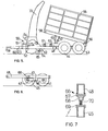
- Figure 5 is a side view of a forage harvesting machine formed as a second embodiment of the present invention;
- Figure 6 is a detail of the embodiment of Figure 5; and
- Figure 7 is a further detail of the embodiment of Figure 5.
- Referring now to Figures 1 to 4 of the drawings the machine illustrated generally comprises a trailer part indicated with the reference numeral 11, and a forage harvesting mechanism generally indicated 12. The forage harvesting mechanism can be one of a number of commercially available types and the construction of it will not be described in more detail herein as it does not form part of the present invention.
- The trailer part 11 comprises a lower chassis part generally indicated 13 mounted on a pair of ground-
engaging wheels 14 and carrying an upper chassis part generally indicated 15 on which is mounted acontainer 16 having four generally upright sides and an open top. The rear wall of thecontainer 16 is pivoted at its upper edge to the side walls, and can be swung open from the bottom by means of alever arrangement 17 operated by acord 18. - The
upper chassis part 15 is pivoted to thelower chassis part 13 at the rear end thereof, for which purpose the upper chassis part :.arries two downwardly projectinglugs 19 which are rigidly secured to theupper chassis part 15 and pivoted to thelower chassis part 13 bypivots 20. Means (not shown) such as an hydraulic ram are connected beiween the upper and lower chassis parts forward of theroad wheels 14 for controlling the angular or entation of theupper chassis part 15 with respect to thelower chassis part 13 whereby to effect tipping o: thecontainer 16 for emptying its contents when required. Thecord 18 is secured at its lower end to the corner chassis part so that the rear wall or tail gate of thecontainer 16 is opened automatically as thecontainer 16 is tipped. - In addition, although again this is not shown, the
container 16 could be provided with a screw auger or other conveyor for discharging its contents either laterally or rearwardly, for which purpose thecontainer 16 would be provided with an opening and a discharge chute either in a side wall or in the rear wall. - The
lower chassis part 13 comprises two mainlongitudinal beam members 21 interconnected by a number oftransverse struts 22, only one of which is shown in Figure 3. Thebeam members 21 are channel section members located with the open side of the channel facing outwardly, that is with the web of the channel facing the other longitudinalfixed beam member 21. The upper flange of thebeam members 21 carries a plurality of spacedstub columns 23 which form supports for the longitudinal members of theupper chassis part 15 when this is lowered to its normal working position. - A forward portion 13a of the
lower chassis part 13, is extendable with respect to the fixed portion carrying the groundengaging wheels 14, and comprises two box sectionlongitudinal members 24 joined at their forward ends by atransverse strut 25 carrying a central forward projectingarm 26 to the lower side of which is connected abox section support 26 carrying a telescopicallyadjustable towing coupling 28 which, in the illustrated embodiment, comprises a ring for an agricultural coupling. Thestrut 26 is reinforced by triangular reinforcingplates 29 at its coupling with thetransverse strut 25 to accommodate transverse loads. - The two longitudinally extendable
box section members 24 are of dimensions to fit slidingly within the channel section fixedlongitudinal members 21, and they carryreinforcement plates 30 on the outer faces thereof.- Towards the rear end of thereinforcement plates 30 there are secured respectiveupstanding lugs 31 having aligned apertures through which passes ashaft 32 which is secured in one of the lugs and projects through the other with asplined end 33. - The
shaft 32 carries a pair ofstraight cut pinions 34 at a position slightly inboard of thelugs 31, which pinions mesh withrespective racks 35 formed on the upper edge ofrack plates 36 which are secured to the inner faces of the fixedlongitudinal chassis members 21 at positions slightly rearwardly of the forward end of these chassis members. - The longitudinal
fixed chassis members 21, theextendable chassis members 24 and thereinforcement plates 30 have two sets of holes which are aligned with one another in the extended and retracted positions of the chassis. Abolt 37 passes through these aligned holes to fix the chassis in its extended or its retracted position. A suitable circular reinforcement plate is secured over the aligned holes in the form of a washer. A similar locking bolt is provided at the rear end of thereinforcement plate 30, and indicated 39 in the drawings. - In use of the apparatus, with the chassis in its extended position the forage harvesting mechanism can be mounted, on
lugs 40 carried by the extendable part of the chassis for this purpose, and the equipment is then usable as a forage harvester to be towed, via thetowing coupling 28, by a tractor vehicle which also drives the forage chopping mechanism via a power take-off shaft and coupling (not shown). During such use theforage chopping mechanism 12 cuts and chops the crop and delivers it through a chute 12a into the open upper end of thecontainer 16 from which it can be discharged by tipping thecontainer 16 on theupper chassis 15 with respect to thelower chassis 13. - When the machine is no longer required for forage harvesting the
forage harvesting mechanism 12 can be removed from thelugs 40. The securingbolts splined end 33 of theshaft 32 the twopinions 34 can be caused to rotate to carry them along therack 35 on therack plate 36. This causes thereinforcement plate 30 which carries the pinion via theshaft 32 and thelugs 31 to move rearwardly retracting the movable forward portion of the chassis and telescopically inserting the movable boxsection chassis members 24 rearwardly into the channel section fixedmembers 21. When retraction is complete the holes in thechannel section members 21 and thebox section members 24 are now re-aligned allowing thebolts forage harvesting mechanism 12 can then be mounted on the chassis for use of the equipment as a forage harvester as before. - In the embodiment of Figures 5, 6 and 7, a forage harvester having a twin wheel bogie is illustrated. The bogie has two
axles wheels main frame members 45 of the bogie, which are pivotally connected at anintermediate point 46. to alug 47 carried by a fixedlongitudinal member 48 of a chassis main frame. - In fact, the chassis is formed in two parts, a first part of which the
frame member 48 constitutes a longitudinal beam, and a second part generally indicated 49 which supports a forage harvesting mechanism generally indicated 50 by means of a system of linkage levers 51, 52 which constitute a quadrilateral linkage between theforage harvester mechanism 50 and the second chassis part 49. A fluid pressure actuator 53 interconnects the second chassis part 49 and theforage harvester mechanism 50, and extension and retraction of this actuator effects raising and lowering of theforage harvester mechanism 50 with respect to the chassis of the forage harvester machine. Thequadrilateral linkage chute 73 is inclined slightly forwardly as the mechanism is raised and a coupling 54 for a connection to a power take-off shaft of a tractor vehicle follows a curved path centred on the coupling point on a tractor vehicle so that raising and lowering of the forage harvesting mechanism can be effected with the tractor vehicle connected by the coupling shaft to the forage harvesting mechanism. - A
container 55 in the form of an open sided box is pivotally mounted by apivot 56 to the rear of thefirst chassis part 48 and afluid pressure actuator 57, preferably an hydraulic actuator, interconnects thefirst chassis part 48 with a lower support frame 58 of thecontainer 55. - The chassis of the forage harvester is thus formed in two parts, comprising the
first chassis part 48 supported via the bogie on theground engaging wheels forage harvesting mechanism 50 and includes acoupling attachment 59 for connecting the harvester to a towing vehicle (not shown) and ajockey wheel 60 for maintaining the harvester in a desired orientation when theforage harvesting mechanism 50 is in its raised position (so that the wheels of the forage harvesting mechanism are lifted from the ground) and the harvester is not coupled to a tractor vehicle. The positioning of ground-engagingwheels coupling 59 on the tractor vehicle. For this reason, thesecond chassis part 48 would normally tend to turn, in an anti-clockwise direction as viewed in Figures 5 and 6, about thepivot 46 with respect to thebogie frame member 45. - The second chassis part 49 is connected to the
first chassis part 48 by means of two lugs 61, 62 on each longitudinal frame member of the second chassis part 49, these having holes therein through which pass respective bolts which also pass through cooperating aligned holes (not shown) in themain frame members 48 of the first chassis part. Astrut 63 pivotally mounted on the underside of thecontainer support frame 58 is engagable on thefirst chassis part 48 to hold thecontainer 55 in the tipped position in which it is illustrated in Figure 5, corresponding to extension of thehydraulic actuator 57 even when the connection to the fluid pressure source on the tractor vehicle is disconnected. This serves as a safety feature and reduces the sealing requirements on the coupling to theactuator 57. Aplate 64 and lockingpin 65 are provided for locking theforage harvesting mechanism 50 in its lowered position where its own ground-engaging wheels are in contact with the ground so that when the first and second trailer parts are separated by releasing the bolts passing through the holes in the lugs 61, 62 the second trailer part can be withdrawn and conveyed on these ground-engaging wheels and thejockey wheel 60. - In such conditions the
first trailer part 48 would now turn about thepivot 46 with respect to thebogie 45 and, in order to prevent this anadjustable locking wedge 66 is provided, this being interpositioned between the forward end of the mainbogie frame member 45 and themain frame member 48 of the first chassis part. This moves the effective pivot point between the first chassis part and the bogie to a vertical position passing through the axis of theforward wheel 44 and the dimensions of the trailer are so chosen that the centre of gravity of the trailer with thecontainer 55 tipped lies between thisaxle 42 and thepivot point 46 so that the trailer will remain balanced on the two ground-engagingwheels - A draw bar suitably shaped to span the free ends of the forwardly projecting
main frame members 48 of the first chassis part, and itself constituting a third chassis part cainow be positioned in substitution for the second chassis part carrying theforage harvesting mechanism 50. The same bolt holes as those which secure the lugs 61, 62 in position can be used for this third chassis part. - In Figure 7 the configuration of a suitable
adjustable locking wedge 66 is illustrated. This comprises a channel sectionupper support platform 67 having a downwardly projectingboss 68 with an internally threaded blind recess. Anangle section foot 69 has an upwardly projecting threadedcolumn 70 which is engaged in the blind threaded opening of theboss 68. Theboss 68 is turnable with respect to thesupport platform 67 so that adjustment to the vertical separation between thefoot 69 and thesupport platform 67 can be effected by turning theboss 68 with respect to thecolumn 70. For this purpose theboss 68 is conveniently provided with a hexagonal cross section for engagement with a conventional key or wrench. Adjustment can be effected, once the wedge is located in position, in order to ensure there is no slack in its position prior to separation of the bolts holding the lugs 61, 62 to the main frame members of thefirst chassis part 48; indeed, by slightly taking the weight of themain chassis part 48 release of the bolts holding the lugs 61, 62 can be facilitated. - Insertion of the
wedge 66 is effected by introducing theplatform 67 under themain beams 48 and sliding theangle section foot 69 which comprises a support platform and lateral flange sideways into engagement with the mainlongitudinal member 45 of the bogie.
Claims (11)
Priority Applications (1)
| Application Number | Priority Date | Filing Date | Title |
|---|---|---|---|
| AT82301563T ATE24089T1 (en) | 1981-03-28 | 1982-03-24 | FORAGE HARVESTER. |
Applications Claiming Priority (2)
| Application Number | Priority Date | Filing Date | Title |
|---|---|---|---|
| GB8109799 | 1981-03-28 | ||
| GB8109799 | 1981-03-28 |
Publications (2)
| Publication Number | Publication Date |
|---|---|
| EP0061896A1 true EP0061896A1 (en) | 1982-10-06 |
| EP0061896B1 EP0061896B1 (en) | 1986-12-10 |
Family
ID=10520740
Family Applications (1)
| Application Number | Title | Priority Date | Filing Date |
|---|---|---|---|
| EP82301563A Expired EP0061896B1 (en) | 1981-03-28 | 1982-03-24 | A forage harvester |
Country Status (4)
| Country | Link |
|---|---|
| EP (1) | EP0061896B1 (en) |
| AT (1) | ATE24089T1 (en) |
| DE (1) | DE3274616D1 (en) |
| IE (1) | IE52836B1 (en) |
Citations (2)
| Publication number | Priority date | Publication date | Assignee | Title |
|---|---|---|---|---|
| AT243177B (en) * | 1964-03-13 | 1965-10-25 | Karl Kirchner Fa | Loading device set up for tractor trains for green or dry forage |
| CH535532A (en) * | 1970-04-25 | 1973-04-15 | Mengele & Soehne Masch Karl | Self-propelled harvest collection wagon |
-
1982
- 1982-03-24 DE DE8282301563T patent/DE3274616D1/en not_active Expired
- 1982-03-24 EP EP82301563A patent/EP0061896B1/en not_active Expired
- 1982-03-24 AT AT82301563T patent/ATE24089T1/en not_active IP Right Cessation
- 1982-03-25 IE IE707/82A patent/IE52836B1/en unknown
Patent Citations (2)
| Publication number | Priority date | Publication date | Assignee | Title |
|---|---|---|---|---|
| AT243177B (en) * | 1964-03-13 | 1965-10-25 | Karl Kirchner Fa | Loading device set up for tractor trains for green or dry forage |
| CH535532A (en) * | 1970-04-25 | 1973-04-15 | Mengele & Soehne Masch Karl | Self-propelled harvest collection wagon |
Also Published As
| Publication number | Publication date |
|---|---|
| IE52836B1 (en) | 1988-03-16 |
| IE820707L (en) | 1982-09-28 |
| ATE24089T1 (en) | 1986-12-15 |
| EP0061896B1 (en) | 1986-12-10 |
| DE3274616D1 (en) | 1987-01-22 |
Similar Documents
| Publication | Publication Date | Title |
|---|---|---|
| US7090066B2 (en) | Unloading system for particulate material | |
| US6282875B1 (en) | Agricultural vehicle and implement with wheels | |
| US8047757B1 (en) | Grain cart having a single auger discharge conveyor | |
| US7134830B2 (en) | Grain wagon with improved grain container | |
| US20050123385A1 (en) | Unloading system for particulate material | |
| US4526265A (en) | Large conveyor assemblies for detachable mounting to a tractor | |
| DE602005005389T2 (en) | Grain wagon with loader for intermodal container | |
| US4621776A (en) | Round bale handler | |
| DE60218500T2 (en) | METHOD FOR THE TRANSPORT AND FILLING OF FREIGHT CONTAINERS | |
| US3413014A (en) | Transportation means for combine header or the like | |
| US4662162A (en) | Tomato harvester | |
| NL8403377A (en) | Loader wagon. | |
| US3090139A (en) | Two-wheeled scraper | |
| US4455034A (en) | Transport device for pull-type swathers and the like | |
| EP3637981A1 (en) | Load transfer device for collecting and transferring harvested material to a transport vehicle | |
| US5528890A (en) | Sprig harvester with pivoting elevator | |
| US8562278B2 (en) | Side-discharge chipper body | |
| EP0061896A1 (en) | A forage harvester | |
| EP3603376B1 (en) | Harvesting machine with a harvesting attachment and a support wheel | |
| DE102004059038B4 (en) | Combination of a harvester, a header and a trolley to support the header | |
| US5580208A (en) | Tractor three-point hitch mounted transporter | |
| US2889172A (en) | Dumping trailer | |
| US10682940B2 (en) | Agricultural dump cart | |
| US4032192A (en) | Latching mechanism for rear gate of dump vehicle with automatic tilt release | |
| US2720424A (en) | Delivery pipe for harvester |
Legal Events
| Date | Code | Title | Description |
|---|---|---|---|
| PUAI | Public reference made under article 153(3) epc to a published international application that has entered the european phase |
Free format text: ORIGINAL CODE: 0009012 |
|
| AK | Designated contracting states |
Designated state(s): AT BE DE FR GB IT SE |
|
| 17P | Request for examination filed |
Effective date: 19830422 |
|
| R17P | Request for examination filed (corrected) |
Effective date: 19830331 |
|
| GRAA | (expected) grant |
Free format text: ORIGINAL CODE: 0009210 |
|
| AK | Designated contracting states |
Kind code of ref document: B1 Designated state(s): AT BE DE FR GB IT SE |
|
| PG25 | Lapsed in a contracting state [announced via postgrant information from national office to epo] |
Ref country code: IT Free format text: LAPSE BECAUSE OF FAILURE TO SUBMIT A TRANSLATION OF THE DESCRIPTION OR TO PAY THE FEE WITHIN THE PRESCRIBED TIME-LIMIT;WARNING: LAPSES OF ITALIAN PATENTS WITH EFFECTIVE DATE BEFORE 2007 MAY HAVE OCCURRED AT ANY TIME BEFORE 2007. THE CORRECT EFFECTIVE DATE MAY BE DIFFERENT FROM THE ONE RECORDED. Effective date: 19861210 Ref country code: BE Effective date: 19861210 Ref country code: AT Effective date: 19861210 |
|
| REF | Corresponds to: |
Ref document number: 24089 Country of ref document: AT Date of ref document: 19861215 Kind code of ref document: T |
|
| PG25 | Lapsed in a contracting state [announced via postgrant information from national office to epo] |
Ref country code: SE Effective date: 19861231 |
|
| REF | Corresponds to: |
Ref document number: 3274616 Country of ref document: DE Date of ref document: 19870122 |
|
| ET | Fr: translation filed | ||
| PLBE | No opposition filed within time limit |
Free format text: ORIGINAL CODE: 0009261 |
|
| STAA | Information on the status of an ep patent application or granted ep patent |
Free format text: STATUS: NO OPPOSITION FILED WITHIN TIME LIMIT |
|
| 26N | No opposition filed | ||
| PGFP | Annual fee paid to national office [announced via postgrant information from national office to epo] |
Ref country code: FR Payment date: 19900309 Year of fee payment: 9 |
|
| PGFP | Annual fee paid to national office [announced via postgrant information from national office to epo] |
Ref country code: GB Payment date: 19900331 Year of fee payment: 9 |
|
| PGFP | Annual fee paid to national office [announced via postgrant information from national office to epo] |
Ref country code: DE Payment date: 19900529 Year of fee payment: 9 |
|
| PG25 | Lapsed in a contracting state [announced via postgrant information from national office to epo] |
Ref country code: GB Effective date: 19910324 |
|
| GBPC | Gb: european patent ceased through non-payment of renewal fee | ||
| PG25 | Lapsed in a contracting state [announced via postgrant information from national office to epo] |
Ref country code: FR Effective date: 19911129 |
|
| PG25 | Lapsed in a contracting state [announced via postgrant information from national office to epo] |
Ref country code: DE Effective date: 19920101 |
|
| REG | Reference to a national code |
Ref country code: FR Ref legal event code: ST |